Setting a Precise Tracking Force
1.After mounting the cartridge on the to-
nearm, rotate the circular weight at the
back of the tonearm until the needle floats
evenly above the record.
2.Hold the circular weight in place and ro-
tate the calibration ring to read zero. The
tonearm should still float evenly above the
record.
3.Rotate the weight until the calibration ring
indicates the desired tracking force.
Care and cleaning
DJs: Don’t use more tracking force than
necessary to prevent skipping. Excess
force will burn records, damage needles,
and reduce sound quality.
Clean the stylus with the supplied clean-
ing brush. Important: brush from the back
to the front only, as shown in Figure 9.
Figure 9. Clean Stylus
Cartridge Replacement
Stylus Stylus Color Stereo Output (1
KHz at 5 cm/sec
peak recorded
velocity)
Frequency
Response in
Hz
Tracking
force
range
(grams)
Typical
Tracking
Force
(grams)
M44–7 N44–7 White 9.5 mV 20 to 20,000 1–3 1.5
M44G N44G Gray 6.2 mV 20 to 20,000 1–3 1.5
M35S N35S Chartreuse 5.0 mV 20 to 20,000 3–5 4
M35X N35X White 6.0 mV 20 to 20,000 1.5–3 2
M70BX N70BX Beige 5.0 mV 20 to 18,000 1.5–3 2
SC35C SS35S Light Blue 5.0 mV 20 to 20,000 4–5 4.5
Table 2. Cartridge Specifications
All Cartridges and Styli
Standard 1/2 Inch mount for DJ turntables
Wide diameter styli for reduced record wear
Optimum Load 47 K Ohms, M44: 400–500 pF. . . . . . . .
M35, M70BX, SC35C: 200–300 pF
Inductance M44: 720 mH. . . . . . . . . . . . . . . . . . . . . . . . . .
M35, SC35C: 425 mH
M70BX: 600 mH
Channel Separation 20 dB at 1KHz. . . . . . . . . . . . . . . . .
Certification
Conforms to European Union Directives, eligible to bear
CE marking; meets European Union EMC Immunity re-
quirements: EN 50 082-1, 1992.
Full One–Year Warranty
Shure Incorporated (”Shure”), 222 Hartrey Avenue,
Evanston, Illinois 60202–3696, warrants to the owner of
this product that it will be free in normal use of any de-
fects in workmanship and materials for a period of one
year from date of purchase. You should retain proof of
date of purchase. Shure is not liable for any conse-
quential damages. If this Shure product has any de-
fects as described above, carefully repack it and send it
prepaid to: Shure Incorporated, Attention: Service De-
partment, 222 Hartrey Avenue, Evanston, Illinois
60202–3696. Outside the United States, return the
product to your dealer or Authorized Service Center for
repair. The product will be repaired or replaced and
returned to you promptly. If it cannot be repaired or
replaced, you may elect to receive a refund. This war-
ranty does not include stylus wear.
Patent Notice
Manufactured under one or more of the following U.S. Patents: 4,275,888; 4,441,177; 4,489,442.
Instalación de la cápsula
Las cápsulas Shure pueden utilizarse con equipos de lo-
cutor o de alta fidelidad. Nota: La M70BX no se recomien-
da para “rasguñado” intensivo.
1. Quite cuidadosamente la aguja de la cápsula. Vea la
Figura 1.
2. Use alicates de punta para conectar los alambres
del cabezal del brazo con las clavijas de la cápsula,
conforme a la Tabla 1. Vea la Figura 2.
3. Acople la cápsula al cabezal con los tornillos que se
suministran. Vea la Figura 3. Apriete los tornillos tras
colocar la cápsula (y el peso del cabezal, si lo desea)
aplicando uno de los métodos que se indican a conti-
nuación.
4. Introduzca la aguja en la cápsula.
Elecciónde un método para colocar la
cápsula
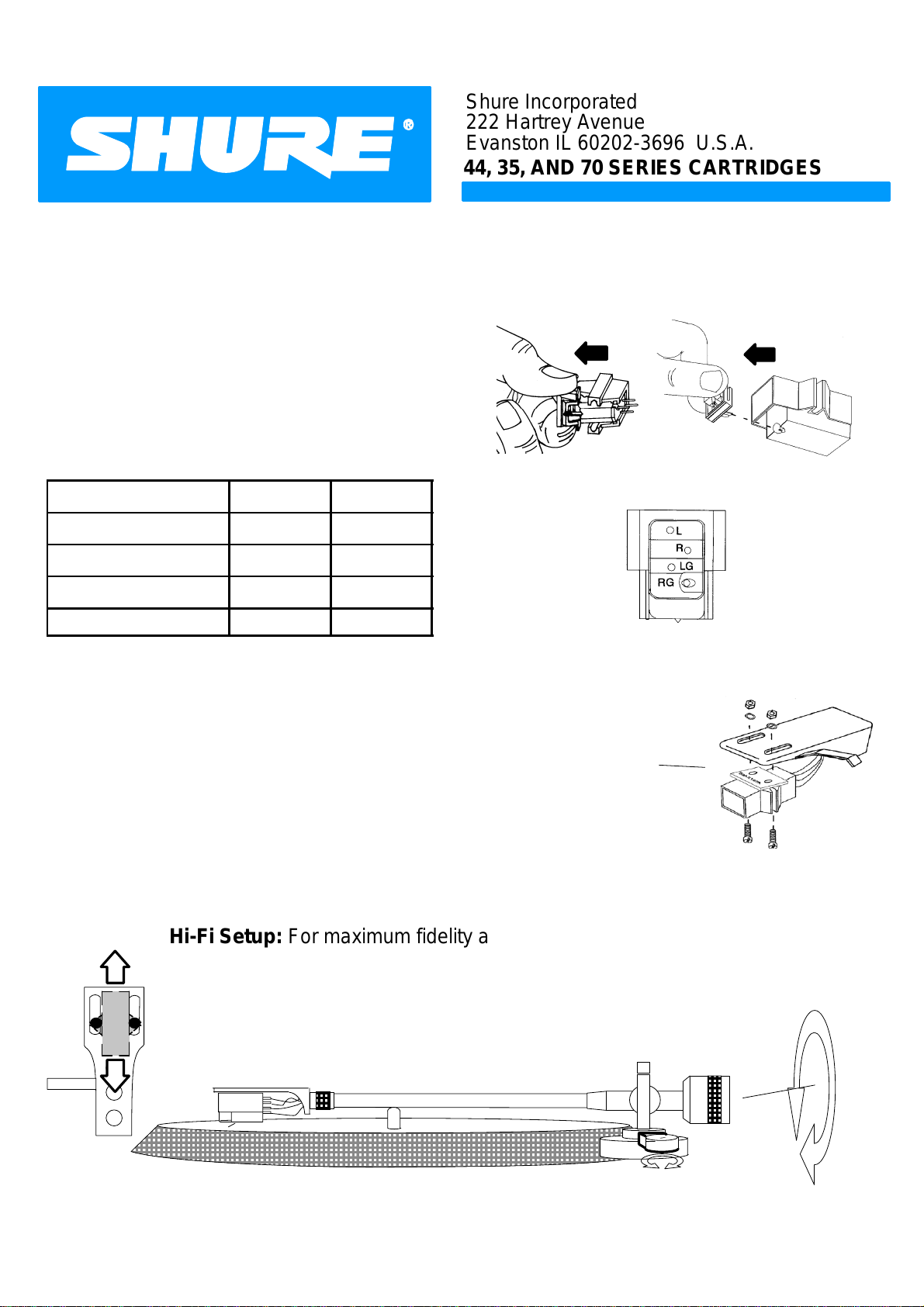
Configuración para alta fidelidad (Figura 4): Para
lograr la máxima fidelidad con el mínimo des-
gaste del disco, coloque la cápsula con un trans-
portador de alineación o un medidor de proyec-
ción que se suministra con el tocadiscos. Nivele
el brazo (vea la Figura 7). Consulte la Tabla 2 y
el apartado “Ajuste de la fuerza de seguimiento
precisa”, que figura más adelante, para ajustar la
fuerza de seguimiento normal correspondiente a
la cápsula. Ajuste el control antipatinaje a la mis-
ma cifra que la fuerza de seguimiento.
Configuración estándar para locutores (Figura 5):
Coloque la cápsula en la parte posterior del ca-
bezal. Ajuste la altura del brazo a 4-5. Ajuste la
fuerza de seguimiento a 3 gramos. Ajuste el con-
trol antipatinaje a 0.
Configuración no ortodoxa para locutores (Figura
6): Invierta el contrapeso y colóquelo a ras con
el extremo del brazo. Coloque la cápsula (con el
peso del cabezal) a ras con el borde delantero
del cabezal. Ajuste el control antipatinaje a 0.
Nivele el brazo: Vea la Figura 7
Ajuste de una fuerza de seguimiento
precisa
1. Tras colocar la cápsula en el brazo, gire el peso cir-
cular situado en la parte posterior del brazo hasta que
la aguja flote uniformemente por encima del disco.
2. Sujete en su sitio el peso circular y gire el anillo gra-
duador hasta que indique el valor cero. El brazo deberá
seguir flotando uniformemente por encima del disco.
3. Gire el peso hasta que el anillo graduador indique la
fuerza de seguimiento deseada.
Resistenciaadicional al patinaje para
locutores
Coloque la cápsula a un ángulo de 23 grados, como se
indica, de modo que la cápsula apunte al pivote del brazo.
Ajuste el control antipatinaje a 0. Vea la Figura 8.
Cuidado y limpieza
1. Locutores: No emplee una fuerza de seguimiento
superior a la necesaria para evitar el patinaje. Una fuer-
za excesiva quema los discos, daña las agujas y redu-
ce la calidad del sonido.
2. Limpie la aguja con el cepillo que se suministra. Im-
portante: Cepille únicamente de atrás hacia adelante.
Vea la Figura 9.
Certificaciones
Cumple las directrices de European Union, califica para
llevar las marcas CE; cumple los requisitos de inmunidad
y compatibilidad electromagnética de European Union:
EN 50 082-1, 1992.
Declaración de patente
Fabricado bajo los términos de una o más de las patentes
siguientes en los EE.UU.: 4,275,888; 4,441,177;
4,489,442.
Garantía de un año
Shure Incorporated (”Shure”), 222 Hartrey Avenue,
Evanston, Illinois 60202–3696, EE.UU., garantiza al
propietario de este producto que el mismo estará libre
de defectos de fabricación y materiales cuando se utili-
za de modo normal por un plazo de un año a partir de
la fecha de compra. Conserve el comprobante de com-
pra. Shure no se hace responsable por daños conse-
cuentes. Si este producto Shure tiene defectos dentro
de las condiciones arriba descritas, embale cuidadosa-
mente la unidad y envíela porte pagado a: Shure Incor-
porated, Attention: Service Department, 222 Hartrey
Avenue, Evanston, Illinois 60202–3696 EE.UU. Fuera
de los EE.UU., devuelva la unidad al distribuidor más
cercano o al centro de servicio autorizado de productos
Shure para su reparación. La unidad se reparará o sus-
tituirá y se le devolverá oportunamente. En caso de no
poder repararse ni sustituirse, puede solicitar la devolu-
ción del importe de compra. Esta garantía no cubre el
desgaste de la aguja.