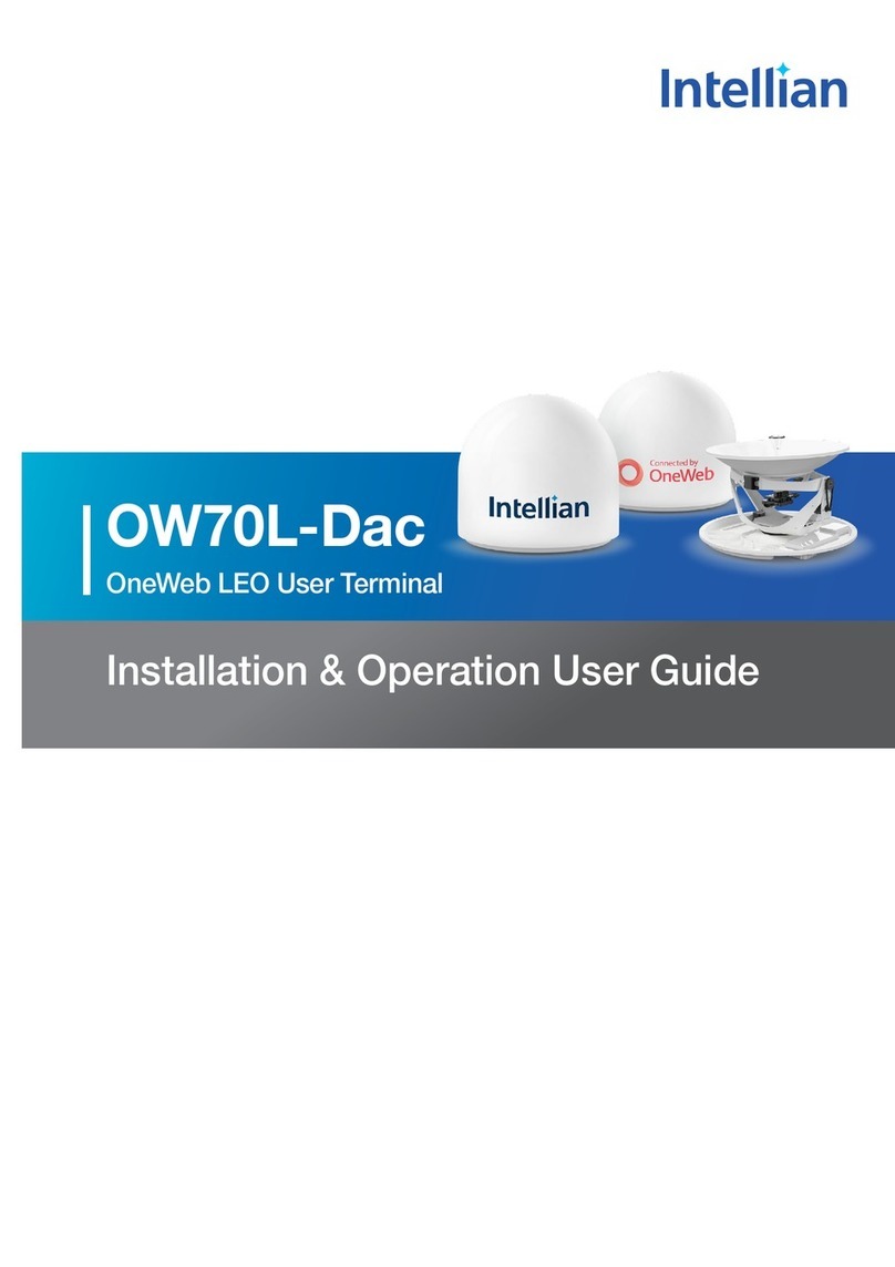
Intellian C700 User manual

Intellian Certus Terminal
C700
Installation & Operation User Guide

Doc. No. UG-KC7001-V1.1
Serial number of the product
This serial number will be required for all troubleshooting or service inquiries.
© 2020 Intellian Technologies, Inc. All rights reserved. Intellian and the Intellian logo are
trademarks of Intellian Technologies, Inc., registered in the U.S. and other countries. The
C700 is a trademark of Intellian Technologies, Inc. Intellian may have patents, patent
applications, trademarks, copyrights, or other intellectual property rights covering
subject matter in this document. Except as expressly provided in any written license
agreement from Intellian, the furnishing of this document does not give you any license
to these patents, trademarks, copyrights, or other intellectual property. All other logos,
trademarks, and registered trademarks are the property of their respective owners.
Information in this document is subject to change without notice. Every effort has been
made to ensure that the information in this manual is accurate. Intellian is not responsible
for printing or clerical errors.
Disclaimer
The information in this user manual is subject to change without prior notice through a
product life cycle. A printed version of the user manual is periodically updated and may
contain inaccuracies or omissions compared to the recent product information. The most
up-to-date information is available on our website at https://www.intelliantech.com.

3
Table of Contents
Table of Contents
Chapter 1. Precautions 8
1.1 Warnings, Cautions, and Notes 8
1.2 General Precautions 8
1.3 Iridium Satellite Network 9
Chapter 2. Certifications 10
2.1 Certications 10
Chapter 3. Introduction 11
3.1 Introduction of C700 11
3.2 Features of C700 11
Chapter 4. Planning Installation 12
4.1 Selecting Installation Site 12
4.1.1 Avoiding RF Interference 12
4.1.2 RF Hazard Precautions 13
4.2 System Package 14
4.2.1 Above Deck Unit (ADU) 14
4.2.2 Below Deck Unit (BDU) 14
4.2.3 Packing List 15
4.3 System Cables 16
4.3.1 RF Cable (Connecting ADU - BDU) 16
4.3.2 DC Power Cable 17
4.4 Unpacking System Package 20
Chapter 5. Installing ADU 22
5.1 Antenna Dimensions 22
5.2 ADU Mounting Hole Pattern 23
5.3 Mast Designing (Installation Example) 24
5.4 Mounting Antenna 26
5.4.1 Mounting Antenna using Inner Holes (with M6 Bolts) 26
5.4.2 Mounting Antenna using Outer Holes (with M10 Bolts) 26
5.4.3 Mounting Antenna on Pole (Optional) 27
5.5 Vent Hole 28
5.6 Connecting RF Cable to Antenna 29

4
C700 - Marine Satellite Communication System
Chapter 6. Installing BDU 30
6.1 BDU Dimensions 30
6.2 Selecting BDU Installation Site 31
6.3 BDU Mounting Template 32
6.4 Mounting BDU 32
6.4.1 Direct Mounting Type 32
6.4.2 19-inch Rack Mounting Type (Optional) 33
6.5 Setting up SIM Card 34
6.5.1 Inserting SIM Card 34
6.6 Antenna System Conguration 35
6.6.1 Data sessions and voice calls 35
6.7 BDU Cable Connection 36
6.7.1 BDU Back Panel View 36
6.8 BDU Connector Pinout Guide 36
6.8.1 LAN Ports (RJ45) 36
6.8.2 Phone Port (RJ14 & 6P4C) 37
6.8.3 General Purpose Inputs/Outputs (GPIO) Connector 38
6.8.4 Power Connector (DC Power) 38
6.8.5 Connecting BDU to ADU (Antenna) 39
6.9 Grounding Stud 39
Chapter 7. Operating BDU 40
7.1 BDU Front Panel 40
7.2 Powering On System 41
7.3 Making POTS Phone Call 41
7.4 Using PoE Devices 42
7.4.1 Accessing Internet 42
7.5 Using Wireless Devices 42
7.5.1 Installing Mobile Application 42
7.5.2 Setting up Wi-Fi 43
7.5.3 Setting up New Extension (Optional) 43
7.5.4 Making Wireless Device Call 44
Chapter 8. Using AptusLX 45
8.1 Introduction 45
8.1.1 How to Access Internal Webpage of BDU 45
8.2 Main Page 46
8.2.1 Page Login 46
8.3 Top Menus 47

5
Table of Contents
8.4 Account Menu 48
8.4.1 User 48
8.5 Dashboard 49
8.6 Status 50
8.6.1 Network 50
8.6.2 Wi-Fi 51
8.6.3 Phone/PBX 52
8.6.4 Data 53
8.6.5 Certus 54
8.6.6 SIM 55
8.6.7 Terminal info 56
8.6.8 External GPIO 57
8.6.9 SDF 58
8.7 Settings 59
8.7.1 Network 59
8.7.2 Wi-Fi 60
8.7.3 Firewall 61
8.7.4 Phone/PBX 62
8.7.5 Data 63
8.7.6 SDF 65
8.7.7 External GPIO 66
8.8 Tools 67
8.8.1 Software Upgrade 67
8.8.2 Backup & Restore 69
8.8.3 Reset 70
8.8.4 Logs 71
8.8.5 Diagnostic 72
8.8.6 Support 73
Chapter 9. Specification 74
9.1 Technical Specication 74
9.2 Environmental Specication 75
Chapter 10. Warranty 76
10.1 Warranty Policy 76
Chapter 11. Appendix 77
11.1 Appendix A. Tightening Torque Specication 77

6
C700 - Marine Satellite Communication System
List of Figures
Chapter 1. Precautions 8
Figure 1: Earth Showing Iridium Satellites in Six Dened Orbital Planes 9
Chapter 4. Planning Installation 12
Figure 2: Potential RF Interference 12
Figure 3: RF Hazard Precautions 13
Figure 4: Above Deck Unit (ADU) / Antenna Unit 14
Figure 5: Below Deck Unit (BDU) 14
Figure 6: Unpacking System Package (with ADU & BDU Sub-package) 20
Figure 7: Unpacking BDU Package 20
Figure 8: Unpacking ADU Package 21
Chapter 5. Installing ADU 22
Figure 9: Antenna Dimensions 22
Figure 10: ADU Mounting Hole Pattern 23
Figure 11: Recommended Mast Design using Inner Holes (with M6 Bolts) 24
Figure 12: Recommended Mast Design using Outer Holes (with M10 Bolts) 25
Figure 13: Mounting Antenna using Inner Holes (with M6 Bolts) 26
Figure 14: Mounting Antenna using Outer Holes (with M10 Bolts) 26
Figure 15: Installing 40A Pole Bushing inside Pole Tube 27
Figure 16: Installing Pole Bracket 27
Figure 17: Mounting Antenna on Pole Mounted Bracket 28
Figure 18: Vent Hole 28
Figure 19: Connecting RF Cable using Inner Holes (with M6 Bolts) 29
Figure 20: Connecting RF Cable using Outer Holes (with M10 Bolts) 29
Chapter 6. Installing BDU 30
Figure 21: BDU Dimensions (Direct Mounting Type) 30
Figure 22: BDU Dimensions (19-inch Rack Mounting Type_Optional) 31
Figure 23: BDU Mounting Template 32
Figure 24: Direct Mounting of BDU 32
Figure 25: Attach Connector Tray to BDU 33
Figure 26: Attach Rackmount Plate to BDU 33
Figure 27: Mount BDU Assembly into 19" Rack 34
Figure 28: C700 System with Connected Devices 35
Figure 29: BDU Back Panel View 36
Figure 30: LAN Ports (RJ45) Pinout 36
Figure 31: Phone Port (RJ14 & 6P4C) Pinout 37

8
C700 - Marine Satellite Communication System
THIS WAY UP
• Place the boxes/crates on the oor with the arrow pointing up.
FRAGILE
• Since the Radome is fragile, handle it with care. Do not apply excessive pressure or
shock. These may cause surface cracking or other damage.
DO NOT STACK MORE THAN FOUR UNITS
• Do not stack boxes/crates more than four units as there is a risk boxes/crates may
fall and be damaged.
KEEP DRY
• Always make sure the antenna is stored on a dry surface in a dry, well-ventilated
area.
• The antenna is designed to withstand a normal rain shower; however, water
resistance cannot be guaranteed if the antenna is submerged.
WARNING
WARNING
WARNING indicates a potentially hazardous situation which, if not avoided, could result
in death or serious injury.
CAUTION
CAUTION
CAUTION indicates a potentially hazardous situation which, if not avoided, could result
in minor or moderate injury or damage to equipment. It may also be used to alert
against unsafe practices.
NOTE
NOTE
A NOTE statement is used to notify people of installation, operation, programming, or
maintenance information that is important, but not hazard-related.
* DO NOT SHIP VIA RAIL: Ensure not to ship any system via Rail.
1.1 Warnings, Cautions, and Notes
WARNING, CAUTION, and NOTE statements are used throughout this manual to emphasize important and
critical information. You must read these statements to help ensure safety and to prevent product damage.
The statements are dened below.
1.2 General Precautions
Before you use the antenna, make sure that you have read and understood all safety requirements.
Chapter 1. Precautions

9
Precautions
* Shock Hazard:
To minimize shock hazard and to protect against lightning, you must connect the equipment chassis
and cabinet to an electrical ground. Make sure the system is correctly grounded and power is off when
installing, conguring, and connecting components.
* Do not operate in an explosive atmosphere:
Do not operate the equipment in explosive environments or in the presence of ammable gases. Operating
this equipment in such an environment causes a denite safety hazard.
* Keep away from living circuits:
Operating personnel must at all times observe all safety regulations. Do not replace components or make
adjustment inside the equipment with any power supply turned on. Under certain conditions, dangerous
potentials may exist in the power supplies even with the power cable removed. To avoid injuries, always
remove the power and discharge a circuit before touching it.
Figure 1: Earth Showing Iridium Satellites in Six Dened Orbital Planes
1.3 Iridium Satellite Network
The Iridium satellite network is comprised of 66 low-earth orbiting (LEO), cross-linked satellites, providing
voice and data coverage over Earth’s entire surface.
At only 476 mi (780 km) from the earth, the proximity of Iridium’s LEO network means pole-to-pole
coverage, a shorter transmission path, stronger signals, lower latency, and shorter registration time than
with GEO satellites. The network is considered a meshed constellation of interconnected, cross-linked
satellites so that each satellite “talks” with the other nearby satellites in front, behind, and adjacent orbits.
In space, each Iridium satellite is linked to up to four others creating a dynamic network that routes trafc
among satellites to ensure global coverage, even when traditional local systems are unavailable.

10
C700 - Marine Satellite Communication System
Chapter 2. Certifications
2.1 Certications
This device complies with part 15 of the FCC Rules and with Industry Canada licence-exempt RSS
standard(s).
Operation is subject to the following two conditions:
(1) This device may not cause harmful interference, and
(2) this device must accept any interference received, including interference that may cause undesired
operation.
L’émetteur/récepteur exempt de licence contenu dans le présent appareil est conforme aux CNR d’Innovation, Sciences
et Développement économique Canada applicables aux appareils radio exempts de licence. L’exploitation est autorisée
aux deux conditions suivantes :
(1) L’appareil ne doit pas produire de brouillage;
(2) L’appareil doit accepter tout brouillage radioélectrique subi, même si le brouillage est susceptible d’en compromettre
le fonctionnement.
Changes or modications made to this equipment not expressly approved by Intellian Technologies, Inc.
may void the FCC authorization to operate this equipment.
Radiofrequency radiation exposure Information:
This equipment complies with RED and FCC, IC radiation exposure limits set forth for an uncontrolled
environment. This equipment should be installed and operated with minimum distance of 1.5 m between the
radiator and your body.
This transmitter must not be co-located or operating in conjunction with any other antenna or transmitter.
Note: This equipment has been tested and found to comply with the limits for a Class B digital device,
pursuant to part 15 of the FCC Rules. These limits are designed to provide reasonable protection against
harmful interference in a residential installation. This equipment generates, uses and can radiate radio
frequency energy and, if not installed and used in accordance with the instructions, may cause harmful
interference to radio communications. However, there is no guarantee that interference will not occur in a
particular installation. If this equipment does cause harmful interference to radio or television reception,
which can be determined by turning the equipment off and on, the user is encouraged to try to correct the
interference by one or more of the following measures:
- Reorient or relocate the receiving antenna.
- Increase the separation between the equipment and receiver.
- Connect the equipment into an outlet on a circuit different from that to which the receiver is connected.
- Consult the dealer or an experienced radio/TV technician for help.

11
Introduction
3.1 Introduction of C700
Intellian C700 maritime satellite terminal utilizes the Iridium®network of 66 Low-Earth Orbit (LEO) satellites,
providing pole-to-pole communication. Using the Iridium Certus®service, the Intellian C700 provides three
high-quality voice lines and the IP data speeds up to 704 kbps. The C700 introduces the most competitive,
highly efcient RF performance, and easy to install solutions that aim to satisfy customers’ demand for a
low cost of ownership in terms of deployment, installation, and efcient operation.
3.2 Features of C700
Superior Data Connection
With the
Iridium Certus
service, the C700 allows for 3 simultaneous high-quality voice calls along with 352
kbps uplink and 704 kbps downlink and up to 256 kbps for IP streaming (future capability).
RF Performance
The 12-element patch antenna improves low elevation angle performance. This innovative electronic phased-
array antenna guarantees a reliable and high-throughput connection in all conditions. Also, the H2 class high
power amplier enables uplink data speeds up to 352 kbps as standard.
Single Coaxial Cable Connection
The BDU and ADU are connected by a single coaxial cable. Ethernet over Coaxial technology allows for both
power and control signals to transfer to the ADU through a single cable with economical cable solutions.
Built-in Security and Networking Features
A powerfully designed Below Deck Unit enables various network features with strong security measures. The
embedded LAN 1 ~ 4 ports allow various IP device connections for simple use such as SIP phones. A dedi-
cated WAN port provides a solution for an alternative data connection, and the dedicated PoE port 1 and 2
allow IP device connections with PoE features. The BDU supports rich network functions such as DHCP, NAT,
Port Forwarding to perform as a router.
Rich Voice Features
C700 supports multi-standard for voice devices. Both wired and wireless SIP phones can be utilized for the
voice connection. Also, BDU can connect the analog phones with the built-in ATA, Analog Telephone Adapter.
In addition, the SIP applications for a smartphone can access the BDU through the Wi-Fi antenna. For these
multiple types of voice equipment solutions, embedded soft PABX maneuvers up to 16 SIP phones for inter
and intra network communications.
Chapter 3. Introduction

12
C700 - Marine Satellite Communication System
The antenna installation requires precaution and safety measures. Failure to follow the correct installation
process may lead to injury of the installer and/or cause damage to the system. In order to maximize the
performance of the system, a thorough review of this installation guide is strongly recommended, as well as
executing the installation process as it is noted in this manual.
4.1 Selecting Installation Site
The antenna should be placed in an area on-board of the vessel with an unobstructed view extending
from (at least) -30° below the horizontal surface in all azimuth direction. When the antenna is transmitting,
obstacles in way of the beam path will cause decreased satellite signal strength. The antenna unit should
have direct line-of-sight with the desired satellite without any obstacles in the beam path. Certain minimum
distances between the antenna and other onboard devices must also be considered during installation.
Do not place the antenna near to a funnel because smoke deposits can cause corrosion of the antenna. In
addition, the deposit can result in any malfunction of the antenna.
Do not place the antenna where there is a direct spray of seawater to avoid percolating any water into the
vent hole.
Chapter 4. Planning Installation
4.1.1 Avoiding RF Interference
Do not install the antenna near the high power shortwave radar. Most radar transmitters emit RF energy
within an elevation range of -15° to +15°. For this reason, It is recommended to position the antenna at least
4.6 m (15.09 feet) away from any radars (s-band, c-band, and x-band radar up to 50kW).
WARNING
WARNING
Never place the antenna in the beam path of the radar regardless of distance. The high power
shortwave radar may impair its performance or damage the antenna.
Radar
+15°
-15°
Antenna
Antenna
Minimum
4.6 m (15.09 feet)
Figure 2: Potential RF Interference

13
Planning Installation
Figure 3: RF Hazard Precautions
4.1.2 RF Hazard Precautions
The antenna is designed to be used with radiation transmitting equipment manufactured by others.
Exposure to RF radiation, including exposure associated with improper use of the transmitting equipment,
may be hazardous to people who work close to the Above Deck Unit. Ensure the safety of personnel who
work with in the system.
During transmission, ensure to keep the minimum safety distance. The recommended minimum safety
distance to the reector on the focal line is about
1 m (3.28 ft)
based on a radiation level of 1 mW/cm that
applies under an uncontrolled environment. No hazard exists >20° below the antenna's mounting plane.
20° 20°
1 m
(3.28 ft)
1 m
(3.28 ft)
RF Radiation Hazard Area

14
C700 - Marine Satellite Communication System
4.2 System Package
4.2.1 Above Deck Unit (ADU)
The Above Deck Unit (ADU) is an antenna unit with 12-element patch antenna, active RF switch circuitry,
BCX (L-band modem), and GNSS circuit. The radome protects the antenna unit from a severe marine
environment. All signals (and DC power) shall pass through a single coaxial antenna cable, which connects
the ADU to the BDU.
Figure 4: Above Deck Unit (ADU) / Antenna Unit
4.2.2 Below Deck Unit (BDU)
The Below Deck Unit (BDU) supports voice and data communications in a marine environment. The BDU
is the main control unit of an antenna system that monitors and controls the antenna operation through
Intellian's web-based software. The BDU contains user interfaces and controls all communication between
the ADU and the local communication devices such as phones, and computers, etc.
Figure 5: Below Deck Unit (BDU)

15
Planning Installation
4.2.3 Packing List
Before beginning installation, make sure you have all the included components.
The ADU Package & BDU Package are provided in one box.
NOTE: The SIM card is provided by the service provider and may be packaged separately.
Above Deck Unit (ADU) Package
Description Q'ty Size Remarks
Above Deck Unit (ADU) 1 370 mm x 370 mm x
270 mm Antenna Unit
LMR200 RF Cable
(TNC/F-TNC/F Type) 1 25 m To Connect ADU - BDU
Antenna Mounting Template 1 Antenna Mounting Template
Hex Bolt 5 M6 x 20L
To Mount Antenna on Mounting Surface
(M6 Bolt Kit)
Spring Washer 5 M6
Flat Washer 5 M6
Hex Bolt 5 M10 x 20L
To Mount Antenna on Mounting Surface
(M10 Bolt Kit)
Spring Washer 5 M10
Flat Washer 5 M10
Below Deck Unit (BDU) Package
Description Q'ty Size Remarks
Below Deck Unit (BDU) 1 315 mm x 190 mm x
42 mm Below Deck Unit
DC Power Cable 1 1 m BDU Power
Ethernet Cable (RJ45 / LAN) 1 1 m To Connect BDU to PC
Wi-Fi Antenna 1
Quick Installation Guide (QIG) 1 Quick Installation Guide
Tapping Screw 5 M5 x 16L To Fix BDU (Direct Mounting Type)
Terminal Block 1 85 mm x 40 mm x
36 mm For Inter-connection of Cables
19-inch Rack Mount Kit (Optional)
The 19-inch Rack Mount Kit can be purchased separately. When this kit is supplied, it is packaged in the
BDU Package.
Description Q'ty Size Remarks
AC Power Cord (USA) 1 1.5 m BDU Power Cord (110 V)
AC Power Cord (CEEE7/7) 1 1.5 m BDU Power Cord (220 V)
AD-DC Adaptor 1 BDU Power Adaptor (150 W)
Rackmount Plate 1
Kit for Rackmount Plate
Pan Head Screw (with Spring
& Flat Washer) 5 M4 x 16L
Connector Tray 1 Kit for Connector Tray
Flat Head Screw 4 M3 x 6L

16
C700 - Marine Satellite Communication System
4.3 System Cables
Make sure of the following before installing system cables.
1. All cables need to be well clamped and protected from physical damage and exposure to heat and
humidity.
2. Don't use any acutely bent cable.
3. Use watertight glands or swan neck tubes on exposed bulkheads or deck heads where the cable passes
through.
4. For installing cables longer than the recommended length, consult with Intellian Technologies rst.
4.3.1 RF Cable (Connecting ADU - BDU)
Due to the signal losses across the length of the RF coax on L-Band, Intellian recommends the following
50 coax cable types for standard system installations. Check the instructions from the cable supplier.
The table below shows the recommended cable types and maximum cable lengths for the antenna system.
Coaxial Cable
Type @900MHz @900MHz loss 13.5 dB Recommended
Max. Cable Length Bend Radius
LMR200 32.6 dB/100 M 0.326 dB/1 M 38.2 M 35 M Installation
12.7 mm (0.5 in.)
LMR300 19.9 dB/100 M 0.199 dB/1 M 62.5 M 60 M Installation
22.2 mm (0.88 in.)
LMR400 12.16 dB/100 M 0.1216 dB/1 M 102.5 M 100 M Installation
25.4 mm (1 in.)
* Maximum DC resistance of RF cable: 1.3
* RF loss at 900MHz: 13.5 dB incl. connector
* Optimal tightening torque for TNC-type connector: 1.5 N-m
Antenna Pole Mount Kit (Optional)
The Antenna Pole Mount Kit can be purchased separately. When this kit is supplied, it is provided in a
separate box.
Description Q'ty Size Remarks
Pole Bracket 1
Pole Tube 1
Hex Bolt 10 M6 x 20L
Spring Washer 10 M6
Flat Washer 10 M6
40A (1½ inch) Pole Bushing 1 For Mounting Aantenn on 40A (1½ inch)
Pole
Socket Set Screw 4 M12 x 12L

17
Planning Installation
4.3.2 DC Power Cable
You can supply DC power to the BDU in the following methods depending on the power supply available in
the vessel. Intellian provides a DC Power Cable, an AC-DC Adapter (optional), and a Terminal Block for the
power connections.
1. Connecting to Battery (default): Using the DC power cable (1 m), supply the DC power to the BDU from
the battery. The power cable is installed with the Molex connector (P/No. 1716920204, Max. AWG 12).
Use 1~2 m (3.28~6.56 ft) length wire for the power supply to prevent voltage drop. If you need a power
cable longer than 2 m (6.56 ft) refer to the following table.
2. Connecting to AC Power Source (optional): Using the AC-DC adapter (110~220V Input, 24 V DC output)
and power cord, supply the DC power to the BDU from the AC power source. (You can nd the AC-DC
adapter in the 19-inch Rack Mount Kit).
Cable length Maximum Wire Size
AWG mm2
5 m (16.40 ft) 13 2.62
10 m (32.80 ft) 11 4.17
20 m (65.61 ft) 9 6.63
* BDU Power Input Range: 10.8~30 V DC
NOTE
NOTE
To connect multiple power cables from the power source, use a Terminal Block (supplied). Refer
to "How to Use Terminal Block" for more details.
How to Use Terminal Block
WARNING
WARNING
Turn off the power before installing the wire nut connector.
KH-6060-3P Specication
Rated Voltage 600V
Rated Current 60A (250V)
Insulation Resistance 100M min.
Dielectric Strength 2,500 VAC for 1min.
Wire 22mm
Terminal Screw M6
Intellian provides a 3-position double-row barrier terminal block as below.
Terminal Block: KH-6060-3P
Barrier type terminal strip:
3 positions, 6 contacts
Position 1 Position 2 Position 3

18
C700 - Marine Satellite Communication System
Red (positive)
Black (negative)
For the DC power wires, Red (positive) and Black (negative), you can
connect each wire with other wires using the terminal block.
1. Open the top cover of the terminal block.
2. Unscrew the 1st position terminal using a Phillips screwdriver. Insert
the ring connector of the Red (positive) wire to the terminal and
tighten the screw back into the terminal.
Terminal Blocks Dimension
Rating/
Pole F(mm) G(mm) Hole(Ø) L(mm) W(mm) H(mm) Weight
60A 3P 28 16 5.2 85 40 36 142g
Wiring Lug Dimension
E 14.5mm
F Min. Ø6.1
W Max. 16.8mm
L 35.5mm

19
Planning Installation
3. Unscrew the 3rd position terminal using a Phillips screwdriver. Insert
the ring connector of the Black (negative) wire to the terminal and
tighten the screw back into the terminal.
Red
(positive)
Black
(negative)
4. Connect wires for distribution to the terminals on the opposite side
of each connected wires.
CAUTION: DO NOT switch positions of the Red (positive) and Black
(negative) wires. Switching the polarity of power may damage the
product.
5. Close the top cover of the terminal block.

20
C700 - Marine Satellite Communication System
4.4 Unpacking System Package
Follow the steps for easy and safe unpacking.
The system package consists of two sub-packages that an
ADU Package and a BDU Package.
1. Remove the top cover and take out the BDU package including a Quick Installation Guide, a BDU Unit, a
Wi-Fi Antenna, a DC Power Cable, an Ethernet Cable, a BDU Bolt Kit, and a Terminal Block.
Figure 7: Unpacking BDU Package
Figure 6: Unpacking System Package (with ADU & BDU Sub-package)
516 (20.31)
516 (20.31)
505 (19.88)
505 (19.88)
505 (19.88)
311 (12.24)
ADU Package
505 (19.88)
505 (19.88)
115 (4.52)
BDU Package
Unit: mm (inch)
DC Power Cable,
Ethernet Cable
BDU Unit
Quick Installation
Guide
Wi-Fi Antenna
BDU Bolt Kit
Terminal Block
Table of contents
Other Intellian Touch Terminal manuals
Popular Touch Terminal manuals by other brands

PayRange
PayRange BluKey Pro Series user manual
Omron
Omron NS7 Series Setup manual

Magna Carta
Magna Carta FacilityPro POS 3000 Installation and user manual
POSIFLEX
POSIFLEX PS-3515-G2 user manual
CC-ISOBUS
CC-ISOBUS CCI 50 operating instructions
BELL LABS INNOVATIONS
BELL LABS INNOVATIONS Lucent Technologies DEFINITY 8410 quick reference

