IntelliCam IR-904 User manual

DocRef#0510601
IR-904 Extended Life- User Guide
Revised 2020-11-07
IR-904
Passive Infrared Sensor
(Extended Life)

DocRef#0510601
IR-904 Extended Life - User Guide
Page 1
Table of Contents
Table of Contents:
Features
Page 02
Chapter 1 - Hardware
Page 03
Chapter 2 - Programming
Page 06
Chapter 3 - Range Test Mode
Page 08
Chapter 4 - Active Mode
Page 09
Appendix A - PIR Best Practices
Page 10
Appendix B - Detection Distances
Page 12
Appendix C - Technical Specifications
Page 13
Appendix D - Contact
Page 14
DocRef#0510601
IR-904 Extended Life - User Guide
Page 2
Features
Features:
●Small Form Factor
●Chameleon™Environmental Adaptive Technology
●Wireless RF Alarm Transmission
●Integrated Coin Cell Battery Pack
●90+ Days Battery Life
DocRef#0510601
IR-904 Extended Life - User Guide
Page 3
Chapter 1 - Hardware
1
Hardware
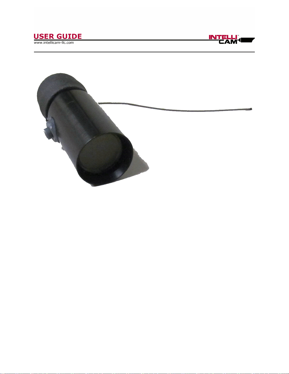
The IR-904 is housed in a small waterproof enclosure.
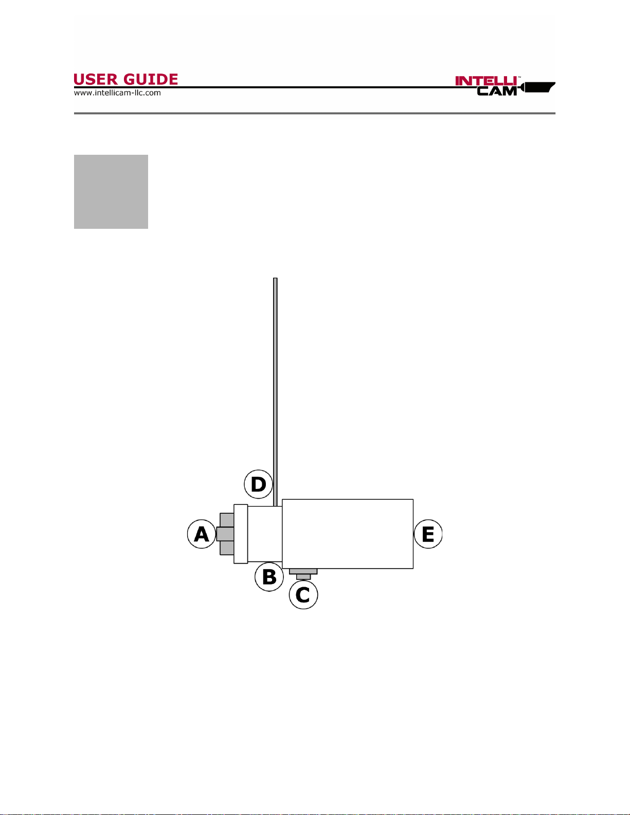
IR-904 SENSOR
A) BATTERY COMPARTMENT
B) RED LED
C) PROGRAMMING BUTTON
D) RF TRANSMIT ANTENNA
E) INFRARED DETECTION LENS

DocRef#0510601
IR-904 Extended Life - User Guide
Page 4
Chapter 1 - Hardware
Battery Compartment:
The BATTERY COMPARTMENT holds two CR1225 coin cell batteries. The IR-904
comes with a small waterproof rubber boot that can be installed over the BATTERY
COMPARTMENT after the batteries are installed.
Programming Button:
The PROGRAMMING BUTTON is used during programming to set the Sensor ID and
Max Sensitivity. The PROGRAMMING BUTTON can also be used to exit the Range
Test Mode.
Red LED:
The RED LED is used during programming to indicate the programming menu is
active, and to play back the programmed Sensor ID and Max Sensitivity. The RED
LED also will illuminate when a range test or alarm is transmitted. After ten
minutes into the Active Mode, the IR-904 will go into Covert Mode, and disable the
RED LED.
RF Transmit Antenna:
The IR-904 needs to be installed so that the RF TRANSMIT ANTENNA is pointing
directly up. This will ensure the best possible RF transmission distance. This will
also ensure the two infrared beams are pointing out horizontally to detect targets
moving horizontally through the IR-904 field of view. The IR-904 should also be
installed so that the RF TRANSMIT ANTENNA is not bent, or immediately impeded
by any solid objects that may decrease RF transmit distance.

DocRef#0510601
IR-904 Extended Life - User Guide
Page 5
Chapter 1 - Hardware
Infrared Detection Lens:
The IR-904 has two invisible beams that point out through the INFRARED
DETECTION LENS. The beams are at a 15 degree angle. Both beams need to be
broken to detect a target. The IR-904 needs to be installed so that the INFRARED
DETECTION LENS is not immediately blocked by any solid objects. (See Page 10
for more information on PIR Best Practices.)

DocRef#0510601
IR-904 Extended Life - User Guide
Page 6
Chapter 2 - Programming
2
Programming
The IR-904 will enter two programming menus
shortly after installing the batteries.
Programming Menus:
When the IR-904 enters the programming menu, the RED LED will illuminate for 5
seconds. The user may press the PROGRAMMING BUTTON to program a Sensor ID
and Max Sensitivity. Each button press will reset the menu timeout to 3 seconds.
After each programming menu, the IR-904 will play back the entered Sensor ID and
Max Sensitivity. If the user does not program a Sensor ID or Max Sensitivity, the
IR-904 will play back the default Sensor ID of 3, or the default Max Sensitivity of 5.
Sensor ID Menu:
The first menu is the Sensor ID menu. The default Sensor ID is ID-3. The user can
program a Sensor ID from 1 to 5 by pressing the PROGRAMMING BUTTON 1 to 5
times. Approximately 2 seconds after powering up the IR-903, the BLUE LED will
illuminate for approximately 3 seconds. While the BLUE LED is illuminated, press
the PROGRAMMING BUTTON for the desired Sensor ID. The IR-903 BLUE LED will
then play back the new programmed Sensor ID followed by the Sensitivity Level. If
the user does not program a Sensor ID, the IR-903 will play back the default
Sensor ID of 3. The Sensor ID is transmitted when the IR-903 detects a target.
The Sensor ID is used by some receivers to perform different functions.

DocRef#0510601
IR-904 Extended Life - User Guide
Page 7
Chapter 2 - Programming
Max Sensitivity Menu:
The second menu is the Max Sensitivity menu. The user can program a Max
Sensitivity from 1 to 5 by pressing the PROGRAMMING BUTTON 1 to 5 times. After
the IR-903 BLUE LED plays back the ID-3, or other programmed Sensor, the BLUE
LED will illuminate for 3 seconds. While the BLUE LED is illuminated, press the
PROGRAMMING BUTTON for the desired Max Sensitivity Level. The LED will then
play back the programmed Max Sensitivity Level.
If the user does not program a Max Sensitivity, the IR-903 will play back the
default Max Sensitivity of 5. The Max Sensitivity determines how far away the IR-
903 can detect a target. Setting a Max Sensitivity less than 5 may be necessary if
there is environmental noise in the IR-903 field of view, and the user wished to
detect targets closer than the environmental noise. Regardless of the Max
Sensitivity, the IR-903 will still use Chameleon™ Environmental Adaptive Technology
to lower the sensitivity if the environment becomes unstable. When the
environment is stable again, the IR-903 will raise the sensitivity back up to the Max
Sensitivity. (See Page 12 for more information on Detection Distances.)

DocRef#0510601
IR-904 Extended Life - User Guide
Page 8
Chapter 3 - Range Test Mode
3
Range Test Mode
The IR-904 has a 3 minute Range Test Mode
to assist in the setup of the receiver.
Range Test Mode:
After both programming menus, the IR-904 will automatically enter the Range Test
Mode. During Range Test Mode, the IR-904 will transmit a Range Test signal every
3 seconds. This Range Test will cause the receiver to briefly illuminate its LED to
indicate that it is still in the range of the IR-904. This is very useful when choosing
where to install the receiver. The Range Test Mode will last for 3 minutes. The
user can exit Range Test Mode anytime by pressing the PROGRAMMING BUTTON.
Range Test Mode with WTM-3:
The WTM-3 has a unique feature when range testing with an IR-904. When the
signal is the strongest, the WTM-3 will flash the Range Test LED three times. As
the signal gets weaker, the Range Test LED will flash two times, then one time,
then not flash at all when the IR-904 is out of range. This unique feature in the
WTM-3 can help the user identify where the signal is the strongest.

DocRef#0510601
IR-904 Extended Life - User Guide
Page 9
Chapter 4 - Active Mode
4
Active Mode
In the Active Mode the IR-904
will be actively detecting targets.
Active Mode:
Immediately after the Range Test Mode, the IR-904 will automatically enter the
Active Mode. During the Active Mode the IR-904 will be detecting targets and also
using Chameleon™ Environmental Adaptive Technology to adjust the sensitivity. When
a target is detected, the IR-904 will transmit an Alarm. After an alarm
transmission, the IR-904 will take up to 3.5 seconds to stabilize and return to the
Active Mode.
Covert Mode:
After 10 minutes in the Active Mode, the IR-904 will disable the RED LED. The IR-
904 will continue to detect targets and use Chameleon™ Environmental Adaptive
Technology to adjust the sensitivity, but when an Alarm is transmitted the RED LED
will NOT illuminate for covert purposes.

DocRef#0510601
IR-904 Extended Life - User Guide
Page 10
Appendix A - PIR Best Practices
A
Appendix A:
PIR Best Practices
Introduction:
The ideal positioning of the IR-904 should optimize target detection and minimize
or eliminate false alarms. The most critical aspect of this is the background of the
IR-904 field of view. The angle at which the IR-904 faces the target path also has
an effect on the detection of the target. The minimum and maximum detection
distances should also be considered when positioning the IR-904. Lastly, the IR-
904 should always be mounted to a solid object that does not move in the wind, or
move in any other circumstances, as this could cause a false activation.
Backgrounds:
The perfect background for the IR-904 field of view is open air. Open air would
require the IR-904 to be positioned perpendicularly to the ground, or angled up
away from the ground, with no solid objects in the field of view. The next best
background for the IR-904 field of view is solid ground. Solid ground would require
the IR-904 to be angled down to the ground with no solid objects in the field of
view. Lastly, the IR-904 can be aimed at solid walls or flat surfaces, but it is
important to note that the two beams should be hitting the same material type.
(Example: If one beam was hitting a metal barn door, while the other beam was
hitting the wood siding of the barn, the different temperature changes of these two
different materials could create a false alarm.) If either of the beams are near
sources of heat or cool air, it could create a false alarm. (Example: Outdoor
heating and cooling units.)

DocRef#0510601
IR-904 Extended Life - User Guide
Page 11
Appendix A - PIR Best Practices
Angle and Detection Distances:
The angle at which the IR-904 faces the target path can determine when or if an
alarm is detected. The IR-904 detects targets moving in a horizontal path. If the
IR-904 is not perpendicular to this path, the beams are essentially widened. If they
are too wide, it will take too long for the target to cross both beams, and the target
will not be detected. If the target is moving at a very fast pace, like a vehicle
traveling 55 MPH, the beams should be further apart to detect the target.
Conversely, if the IR-904 is perpendicular to the road, but is too close, a vehicle
traveling at a very fast pace may not be detected. Similarly, a human target
traveling at a very fast pace less than 5 feet from the IR-904 may not be detected.
(See Page 12 for more information on Detection Distances.)
Note:
●Positioning the IR-904 anywhere from a 90 to 20 degree angle will detect
most targets traveling most speeds.
Mounting:
The provided TC-1 Tree Clip should always be used to mount the IR-904 to a fixed
object. If the object moves, even slightly, the IR-904 will false alarm. Careful
consideration should be taken when positioning the TC-1. Once the TC-1 is
installed, it is easy to rotate the axis of the IR-904 in the same or opposite direction
as the TC-1 was screwed in, but difficult to rotate the IR-904 on the opposite axis.

DocRef#0510601
IR-904 Extended Life - User Guide
Page 12
Appendix B - Detection Distances
B
Appendix B:
Detection Distances
Detection Distances:
Sensitivity 5
Human: 75 feet
Vehicle: 200 feet
Sensitivity 4
Human: 45 feet
Vehicle: 160 feet
Sensitivity 3
Human: 35 feet
Vehicle: 130 feet
Sensitivity 2
Human: 25 feet
Vehicle: 105 feet
Sensitivity 1
Human: 20 feet
Vehicle: 85 feet
Note:
●The vehicle used for testing was a Jeep Wrangler.

DocRef#0510601
IR-904 Extended Life - User Guide
Page 13
Appendix C - Technical Specifications
C
Appendix D:
Technical Specifications
Technical Specifications:
Power
6V DC
Batteries
CR1225 (x2)
Battery Life
90+ days
Current
Sleep: <23uA
RF Transmit: <115mA
Radio Frequency
Domestic: 916.5MHz
International: 868.3MHz
Transmit Power
100mW
Dimensions
2.75” x 1.00” x 1.00” (7.0 x 2.5 x 2.5 cm)
Weight
1.5oz (43g)

DocRef#0510601
IR-904 Extended Life - User Guide
Page 14
Appendix D - Contact
D
Appendix D:
Contact
Contact:
IntelliCam LLC
11138 Air Park Road, Suite H
Ashland, VA 23005
(+1) 804-798-1004
www.intellicam-llc.com
Other manuals for IR-904
1
Table of contents
Other IntelliCam Accessories manuals


