Intelligas GDMS 2 User manual

Intelligas takes every care in ensuring these products reach you in perfect working order.
Each system is tested on dispatch and site induced damage is easily detectable.
Ensure the operation of this unit is explained fully to the kitchen staff.
24 hour technical support line - 02381 290444
GDMS 2
4 Zone Gas Detection System
INTELLIGAS
Gas safety & control systems
INSTALLATION
GUIDE
intelligas.co.uk

INSTALLATION
GUIDE
GDMS 2
INTELLIGAS
Gas safety & control systems
Introduction
Thank you for choosing an Intelligas product. Please follow these instructions to ensure a safe, functional and
long-lasting installation.
This information is important and should be read and understood before attempting installation.
If you are unsure of the terminations and their design voltages or function then refer to this guide or our technical
support line, you can call 02381 290444 or you can text 07952269791 and we’ll get back to you as soon as we’re
available.
Siting the panel
Choose a suitable mounting position for the control unit. Mount the unit away from sources of extreme heat. Ensure the panel is
placed in a position where mechanical damage is unlikely and where it can be easily accessed for use and maintenance.
Fix the panel using the marked enclosure holes only. Take care not to damage the internal wiring or PCB of the unit when drilling.
Under no circumstances should wiring be routed behind the PCB of the control panel.
Control panel supply
All our control panels (except the KVM-SF) should be supplied via a fused spur connection unit. The fuse should be changed to one
that’s rated at 5amps.
KVM-SF ONLY if the panel is supplying the fans directly from the PCB then it should be supplied via a 16amp single phase isolator.
If the panel is controlling Inverters and only the output signals are being used then, as above, the panel should be supplied by a 5amp
fused spur.
intelligas.co.uk

INTELLIGAS
Gas safety & control systems intelligas.co.uk
Field wiring
All wiring from the supply and to the gas valve carries mains voltage (230v ac nominal). The current edition of the IEE Wiring
Regulations should be strictly adhered to, wiring and connections should be made by a suitably qualified electrician or competent
person.
The field wiring voltage to the interlock inputs is reduced to 24 volts, do not connect mains to the air pressure switch terminals,
e-stop, analogue input/output 0-10v control, gas detector or fire alarm terminals.
Please follow the first fix wiring schedule set out below:
1) Main supply 2 core + E 1.5mm (as per regulatory requirements)
2) Gas valve 2 core + E 1.5mm (as per regulatory requirements)
3) Pressure switches 2 core + E 1.5mm (YY type cable)
4) Fire alarm interlock (if req) 2 core + E 1.5mm (FP type cable)
5) Emergency stops 2 core + E 1.5mm (YY type cable)
6) Gas detection equipment, If fitted, 3 core screened (CY type cable)
7) Gas pressure switch, if fitted, 2 core + E 1.0mm (YY type cable)
8) 0-10v signal wiring, if fitted, 2 core 1.0mm (CY type cable)
Where multiple supplies enter a control panel, perhaps in a current sensing interlock. It is preferable that each supply is on the
same phase. If this can’t be achieved, then additional warning labels should fixed in a suitable location on the control panel.
The advice given on these instruction pages, specifically to cable types and ratings may change depending on cable lengths and
installation conditions. If you are not sure about any of the cable types or ratings then contact our technical support team.
INSTALLATION
GUIDE
GDMS 2

INTELLIGAS
Gas safety & control systems intelligas.co.uk
INSTALLATION
GUIDE
GDMS 2
Product Overview
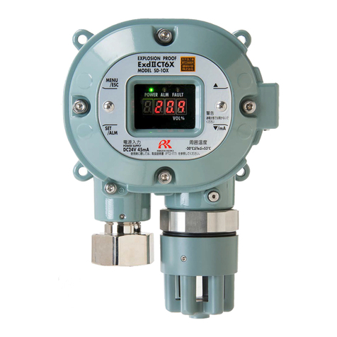
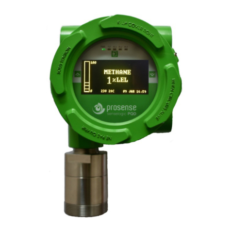
The Intelligas GDMS is a 4 zone gas detection system capable of powering and interpreting detectors of all industry standard types.
4-20ma (3 wire), 0-10 volt (or 2-10v) or switched input type detectors can be connected to the system.
The system has an onboard emergency stop, inputs for additional emergency stops, thermal links and fire alarm.
Additionally the system has outputs for strobe warning lights & sounders. Signalling relays are provided to alert that thermal links
have been operated, pre-alarms and full alarms. Additionally a gas valve output is provided in order to isolate gas supplies where
necessary.
Setting up zone attributes
Each zone needs to be individually setup for each detector type necessary. First of all, setup the input type
using the jumper links next to the terminals.
Once the jumpers have been set for each zone the dip switch must also be set. Use the first bank of 4
switches. The switch for each zone chooses between 4-20ma (on / up) or 0-10v / switched input (off / down)
Once this has been done the system needs to be told which zones are in use, use the second set of dip
switches to select each zone (on / up for zone in use. Off / down for not in use)
Once all these steps have been completed the system can be powered up (please note that changes to the
dip switches settings are only accepted on power up. Any settings changed will require the panel to be
switched off and back on again.
Setting the alarm trip points
Use the pots marked for each zone to set the trip points. E.G. you have a CO2 detector that is 0-10v over a 0-5000ppm scale and
you want the alarm to go off at 2500ppm. That is a set point of 50% of the 0-10v scale. Therefore the pot should set to 50% of its
scale. The software will then automatically set a pre alarm to 75% of the alarm set point.
0-10 volts
4-20 ma
Switched
input (N/C)

INSTALLATION
GUIDE
GDMS 2
Interlock inputs, mains installation and output attributes
The Emergency stop, fire and thermal link
interlocks are all normally closed circuits. If
these aren’t being used then they must be
linked out. As many estops, thermal links and
fire alarm signals can be added, as is neces-
sary, as long as the loop is broken by each
device connected.
See “setting up zone
attributes” on page 4
Beacon output activates on pre alarm and alarm
24v Sounder output activates on alarm and deactivates on
pressing the mute button
Thermal link relay output can be used to operate fire alarms or
I/O modules programmed to alert the buildings occupier.
Pre-alarm and alarm relays operate in conjunction with the fascia LED
indicators. They are reset when the system is reset via the fascia pushbutton
Mains supply
should be via a
local fused spur
fitted with a
5amp fuse using
suitable mains
cable
The feed out to
the gas valve
should also have
a local isolator
near the gas
valve

Flow DirectionFlow Direction
On to appliances
or gas taps
To comply with gas regulations manual
isolation points, purge points and test
nipples may be required. This drawing is
for information only and the necessity of
the above items should be checked to
ensure compliance with the current
regulations.
INTELLIGAS
Gas safety & control systems intelligas.co.uk
Intelligas gas proving system mechanical layout
INSTALLATION
GUIDE
GDMS 2
Table of contents
