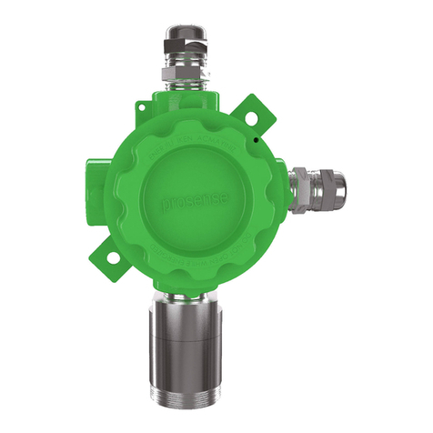
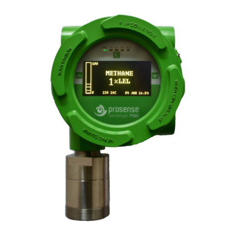
Prosense PQ Series User manual

ProsensePQSeriesQuickInstallationGuide
PRS‐QIG‐PQ‐EN‐Rev.01‐11.2018
Detector connections
Prosensedetectorspreconfiguredtoprovidesignalfromanalogueoutputdependingon
thedetectorandgastype:
Function Value/Setting Meaning
2.0mA Fault
2.0mAto2.5mA Warm‐up
Signaloutput 3mA Calibrationmode
4.0mAto20.0mA Normalgasmeasurement
21.0mA Maximumoverrange
Table1:Detectorsignalleveldetails
DetectorMainboardandconnectiondetailsgiveninDiagram‐1:
Diagram1:Detectormainboardandconnections
Sensorconnectionsareinputtodetectormainboardandalreadyconnectedtosensor
insidethesensorhead.DetectorconnectionsarelistedinTable‐2:
Port Usage
V+ Powerinput(+)12VDC–24VDC
V‐ Powerinput(‐)12VDC–24VDC
S CurrentOutputSignal(4mA–20mA)
RS485‐A SerialconnectionportA
RS485‐B SerialconnectionportB
Table2:Detectoroutputportsandtheirusage
SensorConnections
S
V‐
V+
RS485‐B
RS485‐A
Battery
RelayModule
Connections
Displaymodule
Connections
RS485terminationpins
PowerLED

ProsensePQSeriesQuickInstallationGuide
PRS‐QIG‐PQ‐EN‐Rev.01‐11.2018
Detector Configuration
TheProsensePQdetectorhas4‐20mAanalogueoutputandRS485Modbusserial
communicationoutputfeaturesonmainboard.Itispossibletoinstalloptionalrelay
moduletohavethreerelayoutputsfortwoalarmlevelsandfaultstatus.
4‐20mAoutput:
Thedefaultconfigurationprovidessingle4‐20mAsignaloutput.Prosensedetectorscanbe
connectedtocontrolpanelsonthemarkethaving4‐20mAinputsignal.Signalwiringfrom
detectorandthecontrolpanelshouldbecarriedoutbyshieldedcables.Wirescross
sectiondependsonthedistancebetweenthecontrolpanelandthedetector.Thedetails
giveninpowercablingarevalidaswellforsignaloutput.Pleaseavoidanyinterruptionin
caseanyjunctionsonwires.Theshieldistobegroundedfromthecontrolpanelsideonly
andneverconnecttheshieldtothedetector.Pleasemakesureclutchingorcrimping
apparatusarenotloosenoroxidized.
TogettheanalogueoutputsignalcorrectlyandconstanttheloadresistoronSoutput
shouldbebetween100‐500Ohmsifthepowersourceisgreatedthan15VDC(15‐24VDC)
atdetectorinput.Ifthepowersourceisbelow15VDC(12‐15VDC)theloadresistoronS
outputshouldbebetween100‐300Ohms.Iftheloadresistorbelow100Ohmsthe
detectorwillbehaveastheSoutputisinshortcircuitstatusandenabletheautomatic
outputsavingmoderesultingwithreducingsignallevelto2mA.
Commissioning
WARNING:Thefollowingprocedureshouldbefollowedcarefullyandonlyperformedby
suitablytrainedpersonnel.
Thefollowingprocedurerequiresthedetectorcovertoberemovedwhilecarryingout
supplyvoltagechecks.Therefore,theappropriatepermitstoworkshouldbesoughtin
preparation.PriortocarryingoutanyHOTWORKensurelocalsecurityandsiteprocedures
arefollowed.Ensurethattheassociatedcontrolpaneloutputactuationisinhibitedsoasto
preventfalsealarms.Followbelowstepsforcommissioning:
1. Removethedetectorcover
2. Configurethedetector'sanalogueoutputsignalandpowerinputconnectionscorrectly
3. Checkthatallelectricalconnectionsareterminatedcorrectly
4. SwitchOntheexternalpowersupplytofeedthedetector
5. UsingaDigitalMultiMeter(DMM),checktheSupplyVoltageattheterminalsV+(24V)
andV‐(0V),thisshouldbeaminimumsupplyvoltageof12VDC(Maximumsupply
voltageis24VDC)
6. CheckLEDstatusondetectormainboard.LEDwillbeilluminatedrightafterapplying
power.LEDwillstartblinkingtwiceinasecondduringthewarm‐upperiodand
analogueoutputsignalwillprovide3mA.
7. IfusingPQDcheckLCDscreen.Itwillrunselfchecktestsandreporttheresults.Alltests
shouldendwithOK.IncaseofanyERRORmessagecontactProsense.Whentest

ProsensePQSeriesQuickInstallationGuide
PRS‐QIG‐PQ‐EN‐Rev.01‐11.2018
completedLCDscreenwillshowmonitoringscreenwithdetectorinformationand
WARMUPmessageonstatusline.TheFaultLEDislitinthisperiod.
8. Waittwominutestocompletewarm‐upperiod.IfusingPQD,WARMUPmessagewill
beremovedfromstatuslineandfaultLEDgoneoff.TheLEDonmainboardwillstart
blinkingonceinasecondandanalogueoutputsignalwillbe4mA.
9. SwitchOfftheexternalpowertothedetector.
10. Fitthecoverandmakesurenoneofthecablescauseanobstructionwhilefittingcover
11. Switchonexternalpowertothedetector.
ElectricalSpecifications:
InputVoltageRange 12to24VDC(24VDCnominal)
MaxPowerConsumption Max4Watts.at24VDC
Currentoutput 4‐20mA
2.0mA Fault
2.0mAto2.5mA Inhibit(duringconfiguration/warming)
3mA Calibrationmode
4.0mAto20.0mA Normalgasmeasurement
21.0mA Maximumoverrange
Terminals 3xscrewterminalssuitableforwirediameter0.5mm²to2.5mm²
(20AWGto13AWG).
2xscrewterminalssuitableforwirediameter0.5mm²to2.5mm²
(20AWGto13AWG)forRS485digitaloutput
Relays 3x(1A30VDC,0.5A125VAC,0.3A80VDC).Selectablenormallyopenor
normallyclosed(switch)andde‐energized.
Communication RS485,ModbusRTU
Table3:Electricalspecifications
DetectorBodySpecifications:
Material
Epoxypaintedaluminiumalloyjunctionbox,316‐StainlessSteelSensor
Head
Weight AluminiumAlloy:2kg(withSteelSensorHead)
Mounting Wallmounting
Entries ½NPTand¾NPT(or2x¾NPT)fieldcableentries,¾NPTsensorentry
Table4:Detectorbodyspecifications
Environmental:
IPRating IP65inaccordancewithEN60529:1992
Operating
Temperature ‐20ºCto+70ºC/‐4ºFto+120ºF
OperatingHumidity Continuous20‐90%RH(noncondensing)
Intermittent10‐99%RH(noncondensing)
OperatingPressure 90‐110kPa
StorageConditions ‐30°Cto+70°C(‐22°Fto+158°F)
Table5:Environmentalspecifications

ProsensePQSeriesQuickInstallationGuide
PRS‐QIG‐PQ‐EN‐Rev.01‐11.2018
SAFETY INSTRUCTIONS FOR HAZARDOUS AREA INSTALLATION
ProsensePQseriesgasdetectorsareprojectedandbuiltaccordingtoATEXDirective2014/34/EUwith
referencetostandardEN60079‐0,EN60079‐1.“ATEX“,bytheFrench"ATmosphereEXplosible”,providesthe
technicalrequirementstobeappliedtoequipmentintendedforuseinpotentiallyexplosiveatmospheres.The
scopeofdirectiveistoremovetechnicalbarrierstotradebetweenMemberStatesoftheEuropean
Community.TheProsensePQseriesgasdetectorsmustbeinstalledandmaintenanceaccordingtothesuitable
standardsforelectricalapplicationinpotentiallyexplosiveatmospheres(example:EN60079‐14,EN60079‐17
orothernationalstandards).Readthisinstructionfirstandkeepthisinstructionmanualalwaysavailable.
ThefollowinginstructionsapplytoequipmentcoveredbyATEXcertificatenumber:
1.ProsensePQseriesgasdetectorsmaybeinstalledinhazardousareawithflammablegases,vapours,and
mist,groupII,category2G,maximumsuperficialpermissibletemperature70°C.
Devicecategory2G,IdentificationII2G
ExdbIICT6Gb(Tamb=‐20°C:+70°C)
Itmeans: (EuropeanCommunitylogoforATEXapplications)–groupII(potentiallyexplosiveatmospheres
–surfaceapplication–OTHERthanmines)
Category2G(G=>Gas)–Zone1andZone2
Exdb=>protectionmode:explosionproofenclosure
IIC=>definekindofgases
T6=>Temperatureclass‐‐Maximumallowablesurfacetemperature.
IP65=>Mechanicalprotectiondegree–protectionagainstsolid,dustandliquid.
2.Suitablytrainedpersonnelshallcarryoutinstallationinaccordancewithapplicablecodepractice.
3.Theelectricaldevicesmustbegroundedusingtheirgroundingconnections.Thegroundingconnectionmust
beATEXcertified,suitablefortheapplicationrequired,substances,maximumsuperficialtemperature,and
ambienttemperature.
4.Theusershouldguaranteeperiodicalcleaningoftheplacesweredustcanstoragetoavoidthepalingupto5
mm.
5.Theusershouldnotrepairthisequipment.
6.Theusershouldguaranteethekeepingofthesafetycharacteristicofthedeviceaftermaintenanceof
repairing.
7.Iftheequipmentislikelytocomeintocontactwithaggressivesubstances,itisresponsibilityoftheuserto
takesuitableprecautionsthatpreventitfrombeingadverselyaffected,thusensuringthatthetypeof
protectionisnotcompromised.
Aggressivesubstances:exampleAcids,liquid,gaseswithcanaffectedmetals
8.Toguaranteetherespectoftheprotectiondegreecableglands,blankingelementsandthreadadaptersshall
becertifiedExcomponentsaccordingtoprotection“db”andablankingelementshallnotbeusedwithan
adapter.
9.SinterreplacementshallbedonebyanapprovedtechnicalservicepersonalaccordingtoPQSeriesuser
manual“Sinterreplacement”procedure(PRS‐UM‐PQ‐EN‐Rev.02‐10.2018page44).
10.O‐ringismadeofSiliconeandcontinuousoperatingtemperatureis‐50Cto105C
11.Iftemperatureexceeds70ºCatentryor80ºCatbranchingpointusesuitablyratedcableandcableglands
orconductorsinconduit.
12.Thicknessofouterpaintingisbetween40µm–180µm.
13.MaximumpowerconsumptionofthedetectorwithoptionalboardsinstalledisPmax=4Wwhere
Imax=335mAandVmax=24VDC.
14.Allelectricalconnectionsshouldbemadeinaccordancewithanyrelevantlocalornationallegislation,
standardsorcodesofpractice.Prosensedetectorscanoperatebetween12‐24VDC.Theconnection,
grounding,cablingdetailsareexplainedinthisguideatrelevantsections
Other manuals for PQ Series
2
Other Prosense Gas Detector manuals
Popular Gas Detector manuals by other brands

Dräger
Dräger PIR 7000 Instructions for use

Beghelli
Beghelli Salvalavita manual
Kimo
Kimo FG 100 user manual

CGS
CGS Merlin CO2 TFT Installation operation & maintenance

Silent Call Communications
Silent Call Communications CO5-MCUS Installation and operation manual
AGS
AGS Mini Merlin CH4CO v2 FL Installation operation & maintenance
