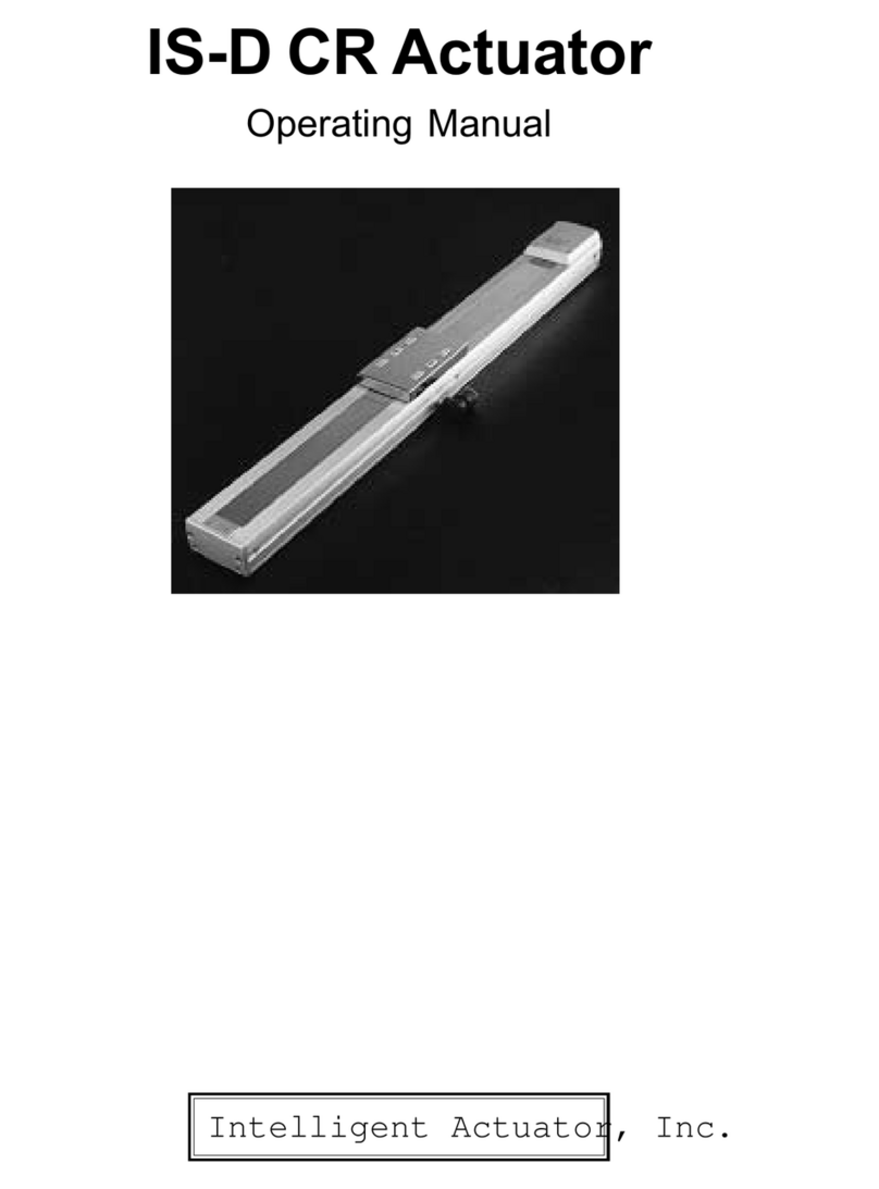
Intelligent Actuator ROBO Cylinder RCP User manual

Intelligent Actuator, Inc.
RCP
Robo Cylinder Controller
Operating Manual
SIO
M.BK
ENC
BAT
PORT
ON
OFF
PORT IN
RLS
BK
NOM
EMG
PIO
24V
N
FG
SW
RDY
RUN
ALM
RDY
RUN
ALM

This publication was written to assist you in better understanding this part of your IA system. If you require further assistance, please
contact IATechnical Support. For Central and East Coast Time Zones, please call our Itasca, IL office at 1-800-944-0333 or FAX 630-
467-9912. For Mountain and Pacific Time Zones, please call ourTorrance, CAoffice at 1-800-736-1712 or FAX 310-891-6015; Monday
thru Friday from 8:30AM to 5:00PM.
IntelligentActuator, Inc.
U.S. Headquarters
2690 W. 237th Street
Torrance, CA 90505
310-891-6015 / 310-891-0815 FAX
IntelligentActuator, Inc.
Midwest Regional Office
1261 Hamilton Parkway
Itasca, IL 60143
630-467-9900 / 630-467-9912 FAX
www.intelligentactuator.com
© Feb 2001 IntelligentActuator, Inc. All rights reserved.
No portion of this publication may be reproduced, stored in a retrieval system, or transmitted, in any form or by any means, electronic,
mechnical, recording, or otherwise, without the prior written permission of Intelligent Actuator, Inc.
Disclaimer
The information and technical data contained herein are subject to change without notice. IntelligentActuator, Inc. assumes no responsi-
bility for any errors or omissions regarding the accuracy of the information contained in this publication.

Pleasebe awareofthe followingbefore youbegin operating theRCP Controller:
(1) WhenusingyourRCPControllervertically(motoruppersideapplication):
Homingproblem may occur dueto payload. In case
thisproblemoccurs,pleasechange
thecurrentlimitvalueduringhoming to75%.
(2) Youmust turn ON the HoldInput Signal of PIO, inorder for the actuator tomove. ForNPN
P10,input is connected to ground, and for PNPP10,inputis connected to+24V.
Before You Begin

Table of Contents
1. SafetyPrecautions ........................................................................................................................................................... 1~6
1-1 Forword .................................................................................................................................................................. 1
1-2 Safety Precautions ......................................................................................................................................................... 2
1-3 Warranty Period and Scope of Warranty........................................................................................................................ 3
1-4 Setting Environment and Noise Measure....................................................................................................................... 4
1-5 Heat Dissipation and Mounting..................................................................................................................................... 6
2. Specifications ........................................................................................................................................................... 7~26
2-1 Connection Method ....................................................................................................................................................... 7
2-2 ExternalDimensionalDiagram ........................................................................................................................................ 9
2-3 Controller Specifications .............................................................................................................................................. 11
2-4 Names of Parts and Functions ..................................................................................................................................... 12
2-5 I/O FlatCable................................................................................................................................................................ 19
3. DataInput(Basic) ........................................................................................................................................................ 27~35
3-1 Position Data Table ...................................................................................................................................................... 28
3-2 Mode Explanation ........................................................................................................................................................ 32
4. Application (Practice) .................................................................................................................................................. 36~56
4-1 Power-Up ................................................................................................................................................................ 36
4-2 Procedure Upfor InitialHoming ................................................................................................................................... 37
4-3 MoveAfter Power-Up (Standard) ................................................................................................................................ 39
4-4 Positioning Mode (2 point reciprocation) .................................................................................................................... 41
4-5 Push Mode ................................................................................................................................................................ 43
4-6 Speed Change Mveoment During Transfer.................................................................................................................. 45
4-7 Movement Using DifferentAccelerationValue • Deceleration Value ........................................................................... 47
4-8 Hold Input ................................................................................................................................................................ 49
4-9 Zone Signal Output ...................................................................................................................................................... 51
4-10 Transfer to Home.......................................................................................................................................................... 53
4-11 Pitch Transfer According to Relative CoordinateAssign ............................................................................................ 54
4-12 Caution Regarding Relative CoordinateAssign ........................................................................................................... 56
5. Parameter List ...................................................................................................................................................................58
6. Alarm list ................................................................................................................................................................ 59~63
7. *Supplement ................................................................................................................................................................ 64~66

P.1
1. Safety Precautions
1-1 Forword
ThankyouverymuchforpurchasingtheRCPController.Withoutknowingbeforehandhowtocorrectlyuseor
operatethecontroller,notonlywilltheuserbeunabletotakefulladvantageofallthefunctionsbuiltintothisproduct
buttheusermightalso,inadvertentlycause damage to the robot orshortenitslife.Pleasereadthismanual as well as
othermanualscarefullypertainingtotheproducttoacquireanunderstandingof the proper methodofhandlingand
operatingthecontroller. Keepthismanual handy so thatyoucan refer to theappropriatesections as theneedarises.
* All precautions have been taken to ensure the accuracy of the contents of this manual. However, if you
become aware of any inaccuracies or discrepancies, please contact your IAI sales representative or
technical service department.
AbsoluteSpecifications:
With the RCPController,oncepower is applied, and homepositionis taught, you canexecute
positioningwithouthomingafterreapplyingthe power. Otherbasicfunctionsare
sameas the standardRC Controller.
•Actuators for Absolute arethe only actuatorthatcan operate usingRCP Controller absolute
specifications.Youmay not usea standard RCActuator.
•(Duringstorage),alwaysremove the battery connector fromthecontroller.Otherwise,battery
willdischarge.
•Datawillbeaffectedwhentheactuatorexperiencesoutsideinputoroscillation(during24Vmain
power OFF) need to be homed on power-up.
• Do not move the slider or rod.

P.2
1-2 Safety Precautions
Please read the following information carefully in order to gain an understanding of safety precautions.
1. Safety Precautions
This product was developed as components for driving automated equipment and is designed not to produce greater torquing or
speed than is necessary. However, strictly observe the following items to prevent any accidents from occurring.
1. As a rule, any handling or operating methods not described in this manual should be viewed as things that should not be
attempted. Please contact the company if any portion of the contents of this manual are unclear.
2. Use only the products specified for wiring between the actuator and controller.
3. Stand clear of the operating range of the machine when it is in motion or is ready to operate. Surround the system with
safety partitions if there is a possibility that people can enter the area where the machine is being used.
4. When assembling, adjusting, or performing maintenance on the machine, always disengage the power supply to the
controller. During work, display a sign stating work in progress where it is readily visible. Also, keep the power cable
close to the operator so that another person cannot inadvertently switch on the power.
5. When more than one person is working on the system, agree on signals beforehand to ensure everyone's safety before
beginning work. In particular, when doing work involving axis movement, always call out for everyone's safety regardless
of whether power is ON or OFF, or the axis is to be mechanically driven or manually moved.
6. When the user needs to lengthen the cables, check the wiring carefully to make sure it is correct before turning the power
ON since miswiring can lead to malfunction.

P.3
1. Safety Precautions
1-3 Warranty Period and Scope of Warranty
The RC Controller undergoes stringent testing before it is shipped from our factory. IAI provides the following warranty:
1. WarrantyPeriod
The warranty period is 12 months from the date the unit is shipped to the customer.
2. ScopeofWarranty
If within the period specified above, a breakdown occurs while operating the controller under normal conditions and is
clearly the responsibility of the manufacturer, IAI will repair the unit at no cost. However, the following items are not
covered by this warranty:
• Faded paint or other changes that occur naturally over time.
• Consumable components that wear out with use (battery, etc.).
• Unit seems to be noisy or similar impressions that do not affect machinery performance.
• Damage resulting from improper handling or use.
• Damage resulting from user error or failure to perform proper maintenance.
• Any alterations not authorized by IAI or its representatives, including parameters.
• Damage caused by fire and other natural disasters or accidents.
The warranty pertains to the purchased product itself and does not cover any loss that might arise from a breakdown of the
product. Any repairs will be done at our factory.
3. Service
The purchase price of the product does not include programming or expenses for sending technicians to the customer's site.
Even if the product is still under the warranty period, separate charges will be assessed for the following services.
• Assistance with unit installation or trial operation.
• Inspection and maintenance.
• Technical training on controller operation, wiring or programming.
• Any other services or work for which IAI normally assesses separate charges.

P.4
1. Safety Precautions
1-4 Setting Environment and Noise Measures
1-4-1 Installation Environment
(1) Do NOT block the air vents of your controller when installing your IA system.
(2) Your controller is NOT dust, water, or oil proof. Take steps to prevent foreign matter from getting into the
controller air vents. Avoid using your IA system in environments subject to contamination by dust, oil, mist, or
cutting oil.
(3) Do not expose your IA system to direct sunlight or place it near a heat source.
(4) Avoid placing your IAsystem under conditions of extreme tempreratures above 40oC or below 0oC (32oF).
The level of humidity should not be exceed 85%. Do NOT expose to corrosive or inflammable gas.
(5) Avoid external vibration, unnecessary impact, or excessive shocks to your IAsystem.
(6) Take steps to shield all cables and wires from electromagnetic noise.
1-4-2 Power Source
Makecertain that110/120VAC or24VDC (rated20.4~ 26.4VDC)is maintained.
If the power supply tends to fluctuate substantially, use a constant-voltage transformer.
1-4-3 Electromagnetic Noise Supression
(1) Wiring and Power Supply
For grounding, please use a dedicated ground of Class 3 or better. The thickness of the cable should be 2.0~5.5mm2 or
larger.
Controller Other
devices Controller Other
devices
Class D
Connection Correct Avoid this method

P.5
1. Safety Precautions
• The most effective method is to install a surge absorber and surge killer in parallel to the reactance load (solenoid and
relay coils). This will reduce noise in a wide band of frequencies.
*Note* Use the shortest possible wiring between the surge absorber
and the noise-creating device. Use of excessively long wir-
ing will decrease the performance of the surge absorber.
(2) Noise Source and Noise Suppression
When using electrical components such as electromagnets, solenoids, or relays which create electromagnetic noise, some
type of noise supression device should be used.
AC solenoid valve · magnetic switch · relay
• Install a surge absorber parallel to the reactance load (solenoid and relay coils).
Surge Absorber (Metal Oxide Varistor or Transzorb).
Surge Killer (Resistor Capacitor Snubber)

P.6
1. Safety Precautions
DC solenoid valve · magnetic switch · relay
• Install a diode parallel with a reactive/inductive load.
• Select a diode with the proper voltage rating. The voltage rating is
determined by the loading capacity of the system.
• When installing the diode, pay careful attention to the polarity of the
diode.Adiodeinstalledin reversepolaritycoulddamage yourIASystem's
internal circuitry.
1-5 Heat Dissipation and Mounting
The size of the controller panel, controller position and cooling method should all be designed so that the controller
boundary temperature remains under 40°C. As the diagram below shows, mount vertically (wall mounting). Since
cooling is done according to natural convection, always mount in vertical direction. Furthermore, as shown in Figure
1-5.2, make sure to leave more than 50mm of space above and below the controller so that enough natural convection may be
attained. When mounting with several controllers lined up, also mount an agitator fan above the controllers in order to
maintain ambient temperature. In addition, the spacing between the controller front side and wall (cover) should be more than
95mm,as shownin Figure1-5.3.
As for the spacing in between the controllers, whether or not it’s a single controller or multiple controllers, please leave
enough space so that controller mounting and removal may be done easily.
RDY
RUN
ALM
SIO
M.BK
ENC
PORT
ON
OFF
PORT IN
RLS
BK NOM
EMG
PIO
24V
N
FG
SW
RDY
RUN
ALM
SIO
M.BK
ENC
PORT
ON
OFF
PORT IN
RLS
BK NOM
EMG
PIO
24V
N
FG
SW
RDY
RUN
ALM
SIO
M.BK
ENC
PORT
ON
OFF
PORT IN
RLS
BK NOM
EMG
PIO
24V
N
FG
SW
RDY
RUN
ALM
SIO
M.BK
ENC
PORT
ON
OFF
PORT IN
RLS
BK NOM
EMG
PIO
24V
N
FG
SW
Over 50mm
Over 50mm
Fan
Over 95mm
Draft
Figure1-4-3
Figure1-5-2 Figure1-5-3

P.7
2-1 ConnectionMethod
2-1-1 Standard Item
2. Specifications
PERSONAL
COMPUTER
PERSONAL
COMPUTER
7
4
1
0
5
2
6
3
8 9
ESC
END
7
4
1
0
5
2
6
3
8 9
7
4
1
0
5
2
6
3
8 9
ESC
BIGIN
END
-
7
4
1
0
5
2
6
3
8 9
SIO
M.BK
ENC
BAT
PORT
ON
OFF
PORT IN
RLS
BK
NOM
EMG
PIO
24V
N
FG
SW
RDY
RUN
ALM
RDY
RUN
ALM
Teaching Pendant
(RCA-T T/D)
Option
Cable length: 5m
Robo Cylinder (RCP)
Cable length: 5m
Cable is option
(CB-RCA-MPA050)
Upper System (Sequencer)
External Connection
(RCA:105-5)
Option
Cable length: 5m
PC
PC Software
(RCA-101-MW)
Option
EMG Switch EMG
24V
N
FG
Cable length: 2m
Flat cable
Attachment
DC24V
Power
(Max 2.5A)
External Connection Unit
(RCA-105-5)
Option
Cable length: 5m
Besides the main communication port
connector (PORT), please do not pull
the connector while the power is ON.
Dissconect from PORT IN only after
PORT switch is turned OFF.

P.8
2. Specifications
2-1-2 Absolute Specifications
Note 1:
When long term power is not supplied to the controller, make sure to remove the battery
connector from the controller. Otherwise, the battery will discharge.
SIO
M.BK
ENC
BAT
PORT
ON
OFF
PORT IN
RLS
BK
NOM
EMG
PIO
24V
N
FG
SW
RDY
RUN
ALM
Note 1
A standard actuator can not be used with a Robo Cylinder
(RCP) Controller. Various cable lengths are optional (Example:
CB-RCA-MPA050 is the part number for 5m cable).
Battery unit attachment

P.9
1
5
2
.8
1
00.5
0.5
1
01
158
1
01
1
0
36.
2
4
1.
6
46.3
90.
5
0.5
3
94.
5
4
6.3
36.6
1
0
158
155
1
4
8
10
φ
5
2-2 ExternalDimenional Diagram
2-2-1 ControllerOuterShape (Standard)
2. Specifications
101
158
158
90.5
101
10
41.6
36.2
46.3
94.5 3
158
148
152.8
5
φ546.3
36.6
10
101
100.5 0.5
0.5

P.10
84
82
φ
5
2
58.8
2
3.2
158
1
4
8
92
102.1
5
15
2
.8
1
00.5
0.5
1
01
158
2-2-2 ControllerOuterShape(IncludesAbsoluteSpecifications and Battery)
2. Specifications
101
5
0.5
158
152.8
148
158
92
102.1
100.5
84
82
2
5
58.8 23.2
5
10.0

P.11
Item
Power Voltage
Ambient Temperature • Humidity
Ambient Environment
Weight
Protective Funtions
LED Display
Specifications
DC 24V +/-10% (Maximum 2.5A)
0 ~ 40°C Humidity under RH 85%
No corrosive gas, especially no excessive gas
E2EPROM check sum error, bank data error, encoder stop determination
error, encoder counter compensation disable error, Encoder breakage,
Speed abnomal, excessive current, main power voltage abnormal, cuircuit
voltage abnormal, absolute counter abnormal (absolute specifications)
RDY (ready) RUN ALM (alarm)
DC 24V Type (ready) RUNALM (alarm)
(Inputs)
Start
Command Position Number (4 bit binary)
Hold
Inputs
and
Outputs
INPUTS
Complete Position Number (4 bit binary)
Positioningcomplete
Homing complete
Zone
Alarm
Emergency Stop
OUTPUTS
Exclusive
6 Ports
Exclusive
9 Ports
Serial Interface I/O
16
Teaching Pendant or PC Software
E2PROM
Number of Positions
Data Input Method
Memory Device
2. Specifications
2-3 ControllerSpecifications
Standard
Absolute Specifications
360g
1200g (includes battery unit)
Caution: Applying voltage over the specifications to the I/O Port will lead to a breakdown.

P.12
2-4-2 Functions
BatteryConnector
This is the connector for the absolute data backup battery (absolute specifications).
EncoderConnector(ENC)
This is the connector for the encoder cable connection.
Port Switch(PORT)
ON: PORT IN Port (Teaching Pendant • PC Software) will be activated.
However, in case of exclusive teaching pendant and exclusive non-connection,
emergency stop status will occur.
OFF: PORT IN Port (Teaching Pendant • PC Software) will be deactivated.
(Since RS 485 line is hot, communication between the controllers will be possible).
MainCommunicationPortConnector (PORTIN)
This is the connector for the teaching pendant or external device communication cable.
This is also the connector for the controller link cable for connection with another controller (axis).
2-4 Names of Parts and Functions
2. Specifications
2-4-1 Names
SIO
M.BK
ENC
BAT
PORT
ON
OFF
PORT IN
RLS
BK NOM
EMG
PIO
24V
N
FG
SW
RDY
RUN
ALM
Battery Connector
(Absolute Specifications)
Encoder Connector (ENC)
Port Switch (PORT)
Main Communication
Port Connector (PORT IN)
Brake Release Switch (BK)
Power and Emergency Stop
Terminal Board
LED Display
Motor • Brake Connector (M•BK)
SIO Connector (SIO)
PIO Connector (PIO)
11 Dip Switch (SW)
4
3
2
1

P.13
Brake Release Switch (BK) Effective only for brake option.
RLS: Release position turns the brake OFF.
NOM: Normal position makes the brake active.
PowerandEmergencyStopTerminalBlock
FG: This is the terminal for connecting earth ground.
N: This is the ground side for 24V power.
24V: This is the DC 24V Power terminal.
EMG: Both of the two terminals are terminals for emergency stop switch connection.
LED Display
RDY: This indicates that the CPU is in normal operation.
RUN: This indicates normal operation.
ALM: This indicates an alarm and or an emergency stop status.
Motor • Brake Connector (M • BK)
This is the connector for actuator motor power / brake power cable connection.
SIO Connector (SIO)
This is the connector for the serial controller link cable connection.
PIO Connector (PIO)
This is the connector for parallel I/O connection.
Dip Switch (SW)
The dip switch has up to 6 numbers, each of the switch functions are listed below.
2. Specifications
FunctionNumber of Dip Switch
1
2
3
4
5
6
Setting switch for actuator addressing
(determines axis #).
Do not attempt to adjust setting.
5
6
7
9
8
10
11

P.14
Dip Switch Number 1~4 • • • Axis Number Setting Switch:
When connecting more than 2 axes onto the SIO connector, serial reorganization occurs when setting the actuator axis number. You
may set up to 0~15 axes (at the time of shipment, numbers 1~4 are all set as OFF. This application is for 1 axis, single unit).
Dip Switch Number
0
1
2
3
4
5
6
7
8
9
10
11
12
13
14
15
1
OFF
ON
OFF
0N
OFF
ON
OFF
ON
0FF
ON
OFF
ON
OFF
ON
OFF
ON
Axis Number 2
OFF
OFF
ON
ON
OFF
OFF
ON
ON
OFF
OFF
ON
ON
OFF
OFF
ON
ON
3
OFF
OFF
OFF
OFF
ON
ON
ON
ON
OFF
OFF
OFF
OFF
ON
ON
ON
ON
4
OFF
OFF
OFF
OFF
OFF
OFF
OFF
OFF
ON
ON
ON
ON
ON
ON
ON
ON
Caution:
Pleasedonotadjustdipswitchnumbers5&6. Pleasedonot adjustthesetting thatwas doneat thetimeof
shipping.Anymissettingwillnotonlylimitbasicfunctions,but willalso,leadtoabreakdown.
Incaseofnumberofaxesgreaterthan1,the emergencystopoftheteachingpendant willonlyeffect thecontroller
axisconnectedtotheteachingpendant.
2. Specifications
Please note:
The controller link cable length is 200mm.
The controller can connect up to a maximum of 16 units.

P.15
2-4-3 Main Communications
SIO Connector Pin Assignment
PIN No.
1
2
3
4
5
6
Signal Name
+5V
SGA
GND
SGB
GND
+5V
Functions
DC 5V Power Output
Line transceiver
Ground for Communication
Line Transceiver I/O Negative Logic Side
Ground for Communication
DC5VPower Output
Main Communication Port Pin Assign
PIN No.
1
2
3
4
5
6
7
8
Signal Name
SGA
SGB
5V
EMGS
EMGA
24V
GND
EMGB
Functions
Serial Communication Channel A
Serial Communication Channel B
5V Power Output
Emergency Stop Status
*Note 1
24V Power Output
Ground
*Note 1
*Note 1: This is used as an emergency stop (B contact).
When disconnecting the emergency stop, please short-circuit.
2-4-4 Specifications for Each Connector Pins and Terminal Board
Motor / Brake Connector (178303-5: AMP)
PORT SW
2. Specifications
Pin No.
1
2
3
4
5
6
Signal Name
B
A
A
BK -
BK +
B
Pin No.
1
2
Signal Name
BAT +
BAT -
Battery Connector (Absolute Specifications)

P.16
Encoder Connector (5484-09AX: Molex)
Pin No.
1
2
3
4
5
6
7
8
9
Signal Name
ENA
ENA
ENB
ENB
ENC
ENC
5V
GND
FG
PowerandEmergencyStopTerminal Block
Pin No.
1
2
3
4
5
Connection
FG
N
24V
EMG 1 (24V)
EMG 2
*Note: Number 3 and number 4 are connected internally.
2. Specifications
2-4-5 I/O Flat Cable
Length: 2m
No.
1
2
3
4
5
6
7
8
9
10
11
12
13
Color
Brown-1
Red-1
Orange-1
Yellow-1
Green-1
Blue-1
Purple-1
Gray-1
White-1
Black-1
Brown-2
Red-2
Orange-2
Cable
Flat
Cable
(A)
Signal
+24V
24G
CSTR
PC1
PC2
PC4
PC8
ILK
PM1
PM2
PM4
PM8
PFIN
ZFIN
ZONE
ALM
EMG
No.
14
15
16
17
18
19
20
21
22
23
24
25
26
B
A
2m
13 26
114
Cut-off
Cut-off
Model Type: CB-RCA-P10020
Signal
Color
Yellow-2
Green-2
Blue-2
Purple-2
Gray-2
White-2
Black-2
Brown-3
Red-3
Orange-3
Yellow-3
Green-3
Blue-3
Flat
Cable
(B)
Cable
Table of contents
Other Intelligent Actuator Controllers manuals
Popular Controllers manuals by other brands
Eaton
Eaton DILE Series instruction manual
Intermatic
Intermatic PE24VA Installation, operation & service manual

Mitsubishi Electric
Mitsubishi Electric MELSEC iQ-R Series user manual
NEC
NEC WL1700-MS installation guide
Carrier
Carrier WTC-RCI-DC Series manual
BERNSTEIN
BERNSTEIN SCR 4-W22-2.6-D2H Installation and operating instructions

Lennox
Lennox HYDROCONTROL Installation, operating and maintenance guide
Beluk
Beluk BLR-CX Operating and Commissioning Instructions
STERWINS
STERWINS EDWC-3 manual

HKC
HKC HM04 Installation and maintenance manual

Samson
Samson TROVIS 5757-3 Mounting and operating instructions
Conrad
Conrad 417536 operating instructions
