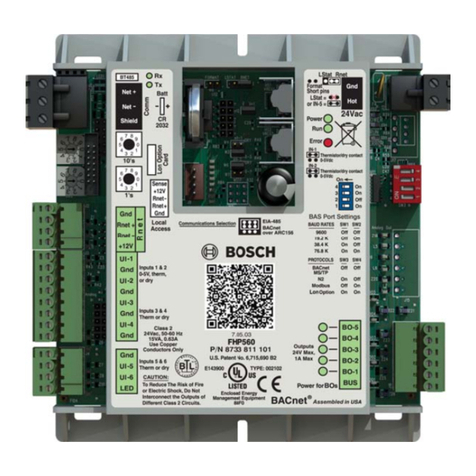
Beluk BLR-CX Installation and operation manual

\\SUSI\Entwicklung\BLR_CX\doku\MB_EN_CX_03.doc Seite 1 von 8 27.01.05
BELUK GmbH !
!!
!D-86956 Schongau !
!!
!Germany
Taubenstr. 1 "
""
"Tel. ++49 8861 2332-0 "
""
"Fax ++49 8861 2332-22
e-mail: blr@beluk.de - http://www.beluk.de
Operating and Commissioning Instruction for BLR-CX
Contents:
Installation page 2
Control Equipments page 2
Commissioning page 4
Alarm Functions page 6
Data Transmission page 6
Connection Diagram page 8
Optional Features
Fan Control incl. H/L-Tariff selecting page 6
Fan Control dependent on temperature
for Power Factor Target change over page 7
Indication of measuring Values page 7

\\SUSI\Entwicklung\BLR_CX\doku\MB_EN_CX_03.doc Seite 2 von 8 27.01.05
Installation
As with all electrical equipment, the appropriate specifications governing electrical installation must be followed when
power factor correction equipment is installed. When removing the front nameplate to adjust the function switch and
DIP switches, always ensure that your body is not carrying any electrostatic charge. This can be accomplished by
simply touching an earthed object, such as the switchboard metal casing to dissipate any electrical charge before
removing the cover plate.
1 Check that the measurement and control voltage, supply frequency and current transformer rating comply with the
ratings given on the back of the relay.
2 Mount the relay in the switch panel
by means of two fixing bolts
3 Connect up in accordance with the wiring diagram. Pay special attention to the cross section size of the C.T.
connections. We recommend for runs up to 10 metres 2,5 mm2 cross section. An integrated voltage
observation with regard to the supply voltage in BLR-CX guarantees a safety-disconnection of the capacitors in
case of excess voltage < 70 % of mains voltage. It must be ensured, that supply voltage is taken from the identical
phase as control voltage for the contactors. Please use specified tool for wiring into the spring terminals. Steel
cover on the rear of the relay must be earthed.
4 Current path of the regulator is designed for current transformers either for 5 A or 1 A secondary coil as well.
Selectable c.t. ratio up to 4000 max. C.t.-ratio setting is only possible for regulators with option M, excludingly
(Regulators with additional energy data indications).
Control Equipments
Behind the removable nameplate there are a multifunction switch (H3) and 2 pushbuttons (+/-) available.
At option “L” (fan control) there are 2 additional DIP switches (S1/S2) fitted for selecting 4 temperature threshold
levels.
At option “M” (Multimeter Functions) 2 additional keys are integrated on front facia for polling off data.
Selecting regulators parameter will be done by means of the +/- pushbuttons with reference to the preselected step of the
multifunction switch (H3). Preselected parameters ex work facilitates commissioning the regulator
All regulators are preset at the multifunction switch (H3) to the following parameter es work:
Multifunction Switch (H3)
0 Any control out of order. Energized steps, if any, will be disconnected after 20 sec. automatically. Selecting of
a threshold level in the range of 10….60 % with reference to the recorded first value of each capacitor step
(equal 100 %) at commission of the plant. Preset value ex work: 50 %. Display indicates “OFF” alternating
with “50”
1 p.f. target set, selectable in the range of 0,70 lag …1…0,90 lead;
preset to cos ϕ= 1,00
2 Switching time delay, selectabel from 5 sec ... 1200 sec. Pushing button + or – for longer than 2 sec. enables rapid
selection.
Preset delay ex work: 40 sec.
3 Fully automatic control of compensation plant. Display indicates the current power factor with either I for
inductive or c for capacitive load (reprinted each 3 sec.) A flashing dot in display above the signs either + or –
signals, that the regulator is selecting a suitable capacitor, if available, with regard to the reactive power deviation
current cos ϕindication each 3 sec.
Energy data available with option Mexcludingly.
4 Manual operation
Manual operation is possible with measuring voltage > 50 V, excludingly, by alternating pushing either the + or the
– button, steps will be activated or deactivated, respectively, to the preset switching time delay in position 2,
accordingly. Letter Hwill be displayed alternating with the current p.f. (1 sec/ 5 sec)
5 Selection of Step Limitation
Step limitation in accordance to the available outputs referring to type of relay CX 04, CX 06, CX 08 or CX 12.
Limitation will be displayed e.g. “CL 12”. Do not exceed the max. available outputs as far as alarm will be
triggered.

\\SUSI\Entwicklung\BLR_CX\doku\MB_EN_CX_03.doc Seite 3 von 8 27.01.05
6 Automatic display of failed Capacitors
Indication of either failed capacitor steps or unengaged outputs. Indication of e.g. “Cd 05” alternating with “Cd
09” indicates, that steps 5 and 9 are failing. “Alarm” (AL_ _) will be triggered synchronously. To reset any alarm
press button + and – for longer than 20 sec. “Cd 0” signals, that no step fails. Automatic control is active all the
time!
7 The number of switching
The number of switching operations per each contactor has made is shown in the display, e.g. “OC 4” for 2 sec.,
then “248”. This indicates, that contactor no. 4 has completed 248 switching operations. Other contactors can be
selected by using the +/- buttons. Only every 10 switching operations the micro processor stores the data. The
stored data of all steps can be cancelled by depressing the +/- buttons together for a time longer than 20 sec.
Automatic control is active all the time!
8 Indication of Step Sizes
The value indicated on display is proportional to the step size, but not calculated in kvar, as far c.t.-ratio is
unknown. It will be displayed e.g. “CC 10” for the 10th step, followed by 2 numbers e.g. “L 74” and “F 84”.
Value “F” stands for the first sensed capacitor size during commissioning and “L” for the last value after, let´s say
several months or years. This is to recognize loss of capacity, if any. If the selected threshold level in pos. 0, will be
decreased due to failed capacitor or blown up fuses, the regulator eliminates this step from control procedure and
triggers alarm “AL”, shown in display. The data per each step may be polled off by means of either + or – button.
To reset the stored data enables by pushing both buttons + and – together for longer than 20 sec. The regulator
starts to come to know each step from the very beginning. Automatic mode is still active in the background.
CX-regulators fitted with option “M” (Indication of energy data) displays the sensed capacitor sizes in real kvar at
correct c.t. setting (see page 5)
.
9 Selecting Mode of Alarm
Selection by means of the push buttons +/-.
Any alarm function is deactivated in selecting “A__0”, no alarm indication will appear. Automatic reset of any
triggered alarm if, e.g. the regulator is able to achieve the preset power factor target again or after any change of
switching direction, up/down, in selecting “A__1”.
Once a triggered alarm will be stored until any manual confirmation in selecting “A__2”.
Reset possible with “A__3”, excludingly.
To reset any triggered alarm, caused either by control procedure (triggered by passing 75 times preset switching
time delay) or by temperature, enables in selecting “A__3” and pushing button +longer than 5 sec. It will be
confirmed by “ArES” in display. Afterwards select requested alarm mode again. Any triggered alarm, caused by
failed steps, is ressettable in position 6of the multifunction switch (H3), excludingly,
at preset alarm mode “A__2”.
(“AL” will be displayed in case of any triggered alarm).
ASelection of a 2nd Power Factor Target
Option “L” 2nd p.f. target will be activated by signal voltage 150-240 V AC on terminals NT/NT1.
Option “LT” 2nd p.f. target will be activated automatically in case of temperature will exceed 57° C
BSelection of an asymmetrical Switching Time Delay.
Selectable range of an asymmetric factor: 1…99 by means of pushing the button + or -. Displaying e.g. “Y_10”
multiplies the preselected switching time (pos. 2) with factor 10 for disconnecting steps (rapid in, slow out; slow in,
rapid out on request). Preset factor ex word = “1”, means symmetrical switching time delay for both directions.
CSelection of a Lock Time at each Change of Switching Direction up/down
An included variable load reversal lock-out time is activated when switching direction changes from “up” to
“down” or conversely. Displaying e.g. “L_30” means a lock time of 30 sec. becomes effective. This lock time will
be added to the preset switching time delay ex pos. 2. This enables to reduce the switching operations at rapid
changing loads. Selectable range of lock time = 1…254 sec.;
preset time ex work: 30 sec.
DSelection of C.T.Ratio (only adjustable with option “M”)
Display indicates “_not”
ESelection of V.T. Ratio (only adjustable with option “M”)
Display indicate “_not”
FSelection of Switching Program by means of pushing button + or -.
After any amendment re-energize the regulator (brief interruption of supply voltage)
Displaying “Auto”: Fully automatic recognition of each capacitor size without fixed program intelligent selection
of the suitable capacitor to achieve the preset power factor target with the minimum of switching operations.
2-phase connection L2/L3.
Displaying “1 1 1 1”: Fully automatic recognition of each capacitor size. Linear switching program up 1….12 and
down 12….0 means FILO/LIFO (first in last out / last in first out). 2-phase connection L2/L3.
Displaying “Eaut”: identical to “Auto”, however 1-phase connection L1/N
Displaying “E111”: identical to “1111”, however 1-phase connection L1/N
Preset ex work: “Auto”

\\SUSI\Entwicklung\BLR_CX\doku\MB_EN_CX_03.doc Seite 4 von 8 27.01.05
Commissioning
1 Apply the supply-, measurement- and control-voltages. Connect the current transformer, and remove any short
circuit link. If measurement voltage is taken from 1 phase against neutral modification must be ensured in position
F of the multifunction switch (H3) followed by a voltage reset of the supply voltage.
Indication “I—O” : no current flowing, resp.: <10 mA of secondary c.t. current. If any capacitors had been
energized before, these steps will be disconnected at once after 5 minutes (possible at parallel operation of capacitor
banks). If regulator is set to manual mode, any energized steps “stand by” all the time.
Indication “U—0” measuring voltage is below 50 V or not connected.
Regulator will start to control, if measuring-voltage is 50 V and reactive component of current 10 mA at least.
If measuring voltage decreases below 50 V any energized steps will be switched off at once after delay of 2 sec.
indipendent on either automatic or manual mode.
2 Ex work preset parameters are:
Power factor target = 1; switching time delay 40 sec.; step limitation to regulator´s maximum; alarm mode = 1;
asymmetrical switching time factor = 1; load reversal lock tim = 30 sec.; c.t.-ratio = 100; v.t.-ratio = 1.0; switching
mode = Auto with 2-phase measuring voltage L2/L3. Any modifications, if requested, may be done via
multifunction switch (H3) and push buttons + or -, as described. Amendments of parameters will be indicated on
display.
Attention: c.t.-ratio and v.t.-ratio exclusive adjustable with option “M”!
The selected parameters will be stored in the regulator, if multifunction switch will be set back into pos. 3
again, only.
3 Ensure, that multifunction switch (H3) is set to pos. 3 (Automatic mode)
4 No volt release lock time of 90 sec. must be passed, before regulator starts to control. During this period steps will
not be activated.
5 Check preset power factor target in pos. 1 and select, if requested.
6 Check preset switching time delay pos. 2 and select, if requested.
7 Check preset step limitation and adapt to the real number of connected capacitors in pos. 5. If any control output of
the regulator remains unengaged, it will be recognized. The regulator tests each free output 3 times to ensure it is
unengaged and will lock this step for 1 day at least, until a voltage interruption or after reset of “CD” in pos.6. Then
these steps will be checked again 3 times each. If there are still “failed steps” detected, they will be recorded in pos. 6;
alarm will be triggered.
8 Check preset alarm mode and select in pos. 9, if requested.
9 Set back the multifunction switch into pos. 3.
10 Display indicates the current power factor cos phi e.g. “i 0.87” for inductive or “c 0.94” for capacitive load.
11 At correct wiring after the no volt release lock time and inductive load a dot in the display at sign “+” will flash.
12 The regulator starts to energize step by step in the rhythm of selected switching time delay in order to achieve the
power factor target. LED`s signal activated steps. Each step must influence the current cos phi. Is there a digital
deviation of the current power factor compaired with the target, dot at sign “+” will flash in case of p.f. is below or
dot at sign “-“ will flash in case of p.f. is above the target.
13 At BLR-CX it is not necessary to preset any C/k-value (threshold level when to start to switch in/out a step), as far
the step sizes will be sensed automatically. The regulator does not follow up a fixed switching program; it will
select a suitable capacitor, if recorded already, in order to achieve the target. During the daily routine all capacitors
will be stored with regard to its size in numbers proportional to the capacitance (see pos. 8 of H3). There is no
indication in kvar , as far the c.t. is unknown. (Exception at option M). At use of equal sized capacitors the
regulator distributes the switching operations equally to the capacitors as much as possible. For special applications
there is a fixed switching program available in the ratio 1:1:1….:1 in pos. F of H3.
14 It may happen, that one of the dot + or – are flashing steadily and the regulator will not switch on/off any step as
far it is not able to find a suitable step size with reference to the deviation from the target p.f. If p.f. is digital
identical with the target, no dot is flashing.

\\SUSI\Entwicklung\BLR_CX\doku\MB_EN_CX_03.doc Seite 5 von 8 27.01.05
15 In case of no existing load a first check of the capacitor bank may be possible in manual mode in pos. 4 at the
multifunction switch (H3) by using push button + for switching on capacitors. Ensure, that measuring voltage is >
50 V AC. In this mode there is no automatic sensing of the step sizes given. Returning back to pos. 3 then the
regulator must disconnect all steps automatically; in this mode the regulator is able to recognize the sizes,
excludingly (see item 13).
Once the required settings or alterations have been made, set function switch (H3) to position 3
“automatic” and replace the front cover plate, so as to inhibit unauthorized interference with relay
settings.

\\SUSI\Entwicklung\BLR_CX\doku\MB_EN_CX_03.doc Seite 6 von 8 27.01.05
Alarm Functions
1 Power Factor Alarm (Display shows: “AL”)
If the predetermined power factor is not abtained in case of insufficient capacitance, the alarm signal is triggered
after elapse of 75 x the selected step switching time, valid for both directions lead and lag. If the set target p.f. is
still surpassed due to overcompensation (welded contacts) after elapse of 75 x the selected step switching time, this
alarm will be triggered, “AL” displayed. To reset any triggered alarm will be possible in pos. 9 of the multifunction
switch (H3) in mode A__3 (see item 9, page 3)
2 Alarm will be triggered as well, if the regulator has detected failed step(s). “AL_ _” will be displayed alternating
with other functions (cos phi) each 5 sec. Reset is possible in pos. 6 of H3 (see page 2).
3 If supply voltage fails, there is no indication in display, contact at terminals
M – MO will close and M – MS opens for external use; switching rate: 3 A at 250 V AC
Data Transmission
BELUK-software “WINBSTO” enables to indicate and recording of power factor, operation cycles, any triggered alarm,
signed with clock and date on PC for purposes of analysis. Each switching operation of the regulator are accompanied with 2
telegrams via TTL-interface (14-pole plug on the rear of casing), one before and one after switching procedure. This enables
to analyze the compensation effect per each step with regard to the influence of the power factor. Storing data on PC requests
a data cable with integrated converter TTL/RS232 for transmitting the data to the PC (extra equipment- length 0,2 m – No.8).
Furtheron it is possible to store data with data logger “DS 21, 22 or 23” locally at the capacitor plant within a defined period
of time. Afterwards the data logger could be taken along for reading out data on PC with the help of a word program.
Optional Features
Option “L” contents 2 functions:
1 Fan Control
In case of increasing the preset temperature threshold level the regulator displays “HA” alternating with
additional indications in the rhythm of 5 sec. For purposes of controlling a fan an output relay closes at
terminal LF/LF1(switching rate 5 A at 250 V AC). Any reset follows automatically in case of decreased
temperature after a “time window” of 8 min. or manually in pos. 9 of the multifunction switch (H3) in
selecting mode “A__3” (see page 3). So the fan will be switched on/off 8 min. at least.
Behind the removable name plate there are 2 DIP switches located for preselecting 4 different temperature
threshold levels as shown below:
If both alarms, power factor and temperature had been triggered, display indicates “AH”; both output relays
will be activated. Reset is possible as described above.
In case of any triggered alarme, referring to p.f. control, during fan is cooling the display indicates “AH” .
Both alarme relays will be activated; any reset is possible as described for each alarme relay, individually.
Temperature 20° 25° 30° 35°
DIP S1 OFF ON OFF ON
DIP S2 OFF OFF ON ON
2 2nd Power Factor Target (High/Low Tariff)
As described in pos “A” of the multifunction switch (H3), there is a second power factor target in the range of
0,70 lag….1….0,90 lead selectable which may be activated via e.g. an external clock switching on a voltage
onto the terminals “NT/NT1” (150….240 V / 45….65 cps) during low tariff period. If this voltage is not
supplied, the regulator controls with reference to the 1st power factor target (high tariff), selected in pos. 1 of
the multifunction switch (H3), accordingly.

\\SUSI\Entwicklung\BLR_CX\doku\MB_EN_CX_03.doc Seite 7 von 8 27.01.05
Option “LT”:
This implies option “L” automatically (see item 1). After exceeding the temperature threshold level of 57° the 2nd power
factor target will be activated (hysteresis 4°)
Nange over onto a 2 an powerfactor target via double-tariff control is impossible (s.item 2).
Option “M”
Regulators with this option are fitted with a modified facia contenting 2 pushing keys signed + and -; they replace the former
push buttons behind the name plate. This option requests the setting of a c.t.-ratio in order to get correct indication of energy
data in display. At big plants an automatical change of scale from e.g. kW to MW is provided, means indication changes
from 9999 kW to 10.0 MW. Any indication will be overwritten each 3 sec.
In the pos. Dand Eof the multifunction switch (H3) c.t.- and v.t.-ratio must be preset:
D = c.t.-ratio:
By using key + or – in the range of 1….4000 (e.g. 800A/5A =160)
preset ex work 100, pushing key longer 2 sec. enables rapid selection.
E = v.t.-ratio:
By using key + or – in the range of 1.0….350.0 (e.g. 20 kV/0,1kV =200)
preset ex work 1.0, pushing key longer 2 sec. enables rapid selection.
CX..M indicates following energy data selectable by using key + or -:
CPower Factor
UMeasuring voltage
ICurrent of the sensed phase
PTotal active Power
STotal apparent Power
qTotal reactive Power
FFrequency
Option “k”
Combi Filter Switching Program
It must be ensured, that at combi filter banks the numbers of energized steps with higher choke ratio (e.g. 12 %) are more
than with the lower choke ratio (e.g. 7 %)
For this purpose there is the switching program “Combifilter” available. It must be mentioned in purchase order for providing
ex work.
Furtheron it must be ensured, that the higher choked steps are connected to the odd and the lower choked steps the even
outputs of the regulator.

\\SUSI\Entwicklung\BLR_CX\doku\MB_EN_CX_03.doc Seite 8 von 8 27.01.05
1 or 5A
1 Phase CX-04CX-06 CX-12
CX-08
45 - 65 Hz
PE
L2 L3 NT1
t
2-Phase L1/NL2/L3
12
Consumers
L
Grid
45/65Hz Measuring
45-65Hz
x/1A
x/5A
50 - 530V
0
90-132V
198-253V
C1-12
Control Outputs
MS
Alarm
LF LF1
Fan
250V
3 A 250V
5 A
NT
150 -240
VAC
NT
N )( L1
220 -240
VAC
ON =NT
OFF=HT
11/03
Connection Diagram
4 A
L2
4 A
L3
4 A
A123456789
Rotationfield
10 11
Grid
N
L2
L3
L1
N L MOMKL
S1 S2 H3 +
Control Equipment
Other manuals for BLR-CX
1
Table of contents
Other Beluk Controllers manuals

Beluk
Beluk BLR-CM Modbus Guide

Beluk
Beluk BLR-CM Training manual
Beluk
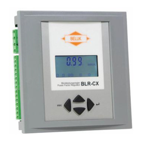
Beluk BLR-CX User manual
Beluk
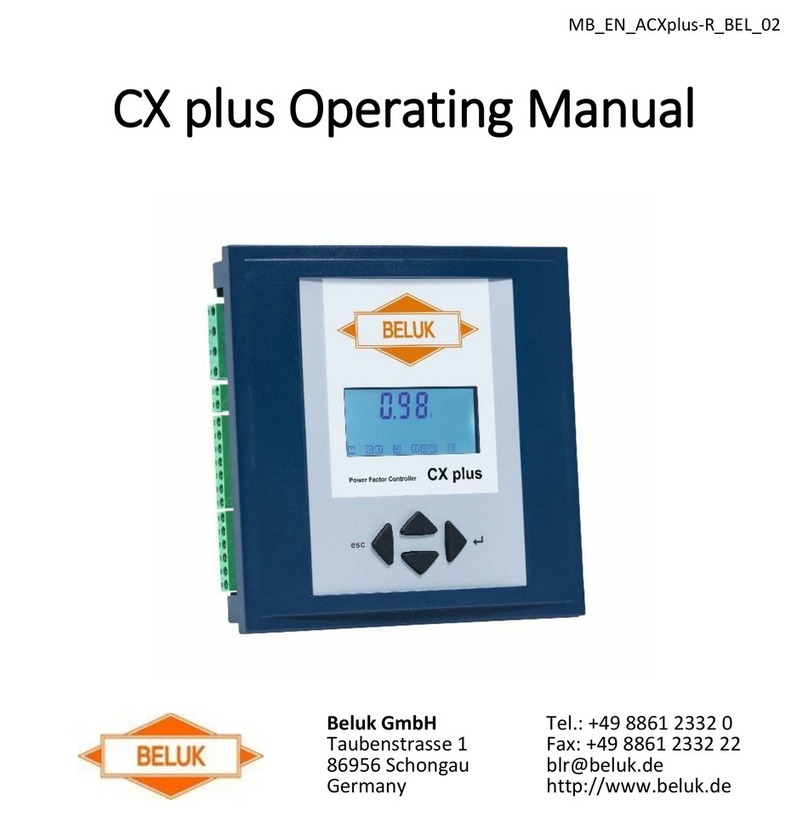
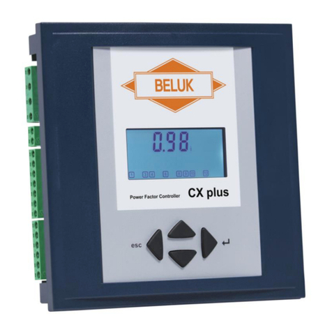
Beluk CX plus User manual
Beluk
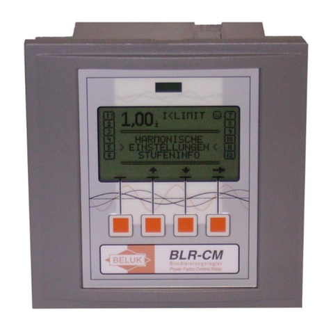
Beluk CX plus User manual
Beluk
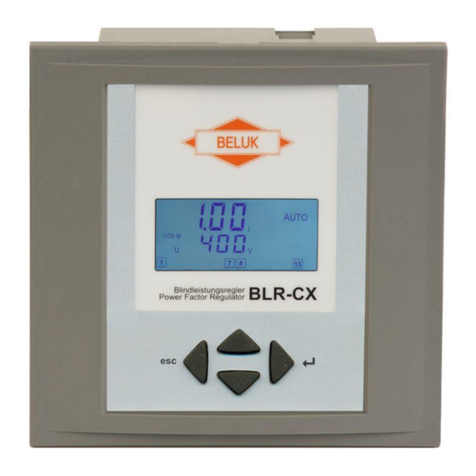
Beluk BLR-CM 3 phase User manual
Beluk
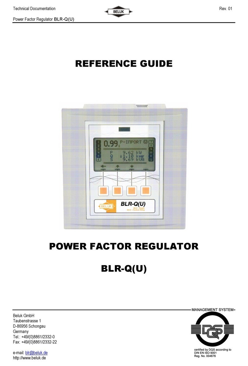
Beluk BLR-CX-R User manual
Beluk
Beluk BLR-Q(U)06/12R User manual

Beluk
Beluk CX plus User manual

Beluk
Beluk CX plus User manual
Popular Controllers manuals by other brands
AUMA
AUMA SG 05.1-F05 operating instructions
Kutai electronics
Kutai electronics ADVR-250 Operation manual
Milnor
Milnor MilTouch MWF27Z8 Series Operator's guide

Mitsubishi Electric
Mitsubishi Electric NZ2GF2BN-60DA4 user manual
Nordson EFD
Nordson EFD ValveMate 7140 quick start guide

Shibaura
Shibaura COMPO ARM BE50 instruction manual
