Intelligent Charging MB/TS25 PC211 User manual
MB/TS25 PC211 UPGRADE Battery Charger
Operators Manual
Doc: DWG1006-34-R3 TS25 PC211 Upgrade Operators ma ual.odtPage 1 of 44 Copyright Material of Intelligent Charging Limited © 2015
Printed On : 02/09/15
MUTE
EXTD
ENTR
DISP DATA
A SET PROC
V SETTEST BATT
CHRG T SET
START
STOP
EXTD
ENTR
DISP DATA
A SET PROC
V SETTEST BATT
CHRG ONE T SET
START
STOP
VOLTS TIME
AMPS
TEST
END ONE
VOLTSTIME
AMPS
TEST
END
%
%
ALARM
MEM
Bxx
ON
OFF
I
O
MEM
Bxx
ON
OFF
I
O
MEM
Bxx
ON
OFF
I
O
MEM
Bxx
ON
OFF
I
O
I N T E L L I G E N T C H A R G I N G
CHARGE
TRIP
ANALYSER
TRIP
MAINS
POWER
BATTERY 'B'BATTERY 'A'
BATTERY 'B'BATTERY 'A'
MB/TS25 PC211 UPGRADE
BATTERY
CHARGER/ANALYSER
OPERATORS MANUAL

MB/TS25 PC211 UPGRADE Battery Charger
Operators Manual
T BLE OF CONTENTS
1 MANUAL REVISION HISTORY 3
2 TS25 PC211 UPGRADE DESCRIPTION 4
2.1 GENERAL NOTES 4
2.2 DIFFERENCES 4
3 CONTROLS AND INDICATORS 5
3.1 DISPLAY 6
3.2 POWER SWITCH 7
3.3 AUDIBLE ALARM 7
3.4 CHARGE CAPACITY TEST CIRCUIT BREAKERS 7
3.5 BATTERY CONNECTORS 7
3.6 KEYBOARD 8
4 USING THE TS25 UPGRADE 9
4.1 CONNECTING BATTERIES 9
4.2 CAPACITY TESTING BATTERIES 12
4.3 CHARGING BATTERIES 15
4.4 ENTERING BATTERY DATA 18
4.5 USING THE ONE MODE OF OPERATION 20
4.6 RESETTING THE TS25 UPGRADE 20
4.7 DISPLAY MNEMONICS 22
4.8 ERROR CODES 23
5 CALIBRATION 25
Doc: DWG1006-34-R3 TS25 PC211 Upgrade Operators ma ual.odtPage 2 of 44 Copyright Material of Intelligent Charging Limited © 2015
Printed On : 02/09/15

MB/TS25 PC211 UPGRADE Battery Charger
Operators Manual
5.1 EQUIPMENT REQUIRED 25
5.2 PERFORMANCE CHECKING 25
5.3 RE-CALIBRATION 26
5.4 CALIBRATION PROBLEMS 28
5.5 CALIBRATION EQUIPMENT CONNECTIONS 29
6 ROUTINE MAINTENANCE 30
6.1 INTERNAL BATTERY REPLACEMENT 30
7 BATTERY LIBRARY 31
7.1 RETRIEVING A LIBRARY ITEM 31
7.2 ENTERING OR MODIFYING A LIBRARY ENTRY 31
8 DEFAULT BATTERY LIBRARY 32
9 SPECIFICATIONS 42
10 PRODUCT DISPOSAL INSTRUCTIONS 43
1 Manual Revision History
Rev Date Description
0 12-02-2008 First Written
1 10-03-2009 Removed Warranty Section. dded New Battery Details To Library.
2 24-11-2014 Changed drawings so that an actual TS25 model is shown.
Doc: DWG1006-34-R3 TS25 PC211 Upgrade Operators ma ual.odtPage 3 of 44 Copyright Material of Intelligent Charging Limited © 2015
Printed On : 02/09/15

MB/TS25 PC211 UPGRADE Battery Charger
Operators Manual
2 TS25 PC211 UPGRADE DESCRIPTION
2.1 GENERAL NOTES
You have chosen to have your TS25 Model battery charger analyser upgraded to a
TS25 (UPGR DE) Model.
The upgrade involves the removal of the antiquated processor board (PC200) and the
separate display board (PC204) to the new PC211 combined display and processor
board.
This upgrade extends the life cycle of your equipment by employing a fully supported
processor unit with higher accuracy speed and functionality.
Some TS25 units will be also be able to benefit from the upgrades ability to increase
the charging current from 10 to 12 (24 in one mode).
Operation of the unit is predominantly the same but there are differences because of
the extended functionality. It is important that this manual is read carefully before
undertaking control of the unit to establish the minor differences and how to employ
them.
2.2 DIFFERENCES
When accessing data entry functions the STOP key can be pressed to BORT the data
entry mode.
The library has been modified to list the standard set of batteries used by the UK MOD.
Check the data with manufacturers data sheets before using any data library entries.
ccessing constant voltage and constant current charging modes are no longer done via
the library number. Use the PROC key to set the charge mode. This is also preserved
with the library data.
utomatic calibration checks to ensure that wrongly entered values are not used, which
could potentially damage the battery or unit.
ll process terminations are highlighted with an “E” number to indicate to the operator
why a capacity test or charge has stopped.
Start and run-time checks are employed to ensure that wrongly entered data does not
make the unit perform outside of its capabilities, the run—time checks also test for
battery disconnection while being processed, wrongly connected battery and checks for
possible internal faults. Extra runtime checks are done to ensure that both cables are
connected when used in ONE mode.
The unit now employs 12 bit nalogue to Digital conversion devices which have
dramatically improved its stability and accuracy.
bility to view the firmware revision and internal resets can be accessed by the keypad.
The ONE mode of operation where both channels can be connected in parallel to double
charge or discharge rates has been simplified.
Doc: DWG1006-34-R3 TS25 PC211 Upgrade Operators ma ual.odtPage 4 of 44 Copyright Material of Intelligent Charging Limited © 2015
Printed On : 02/09/15

MB/TS25 PC211 UPGRADE Battery Charger
Operators Manual
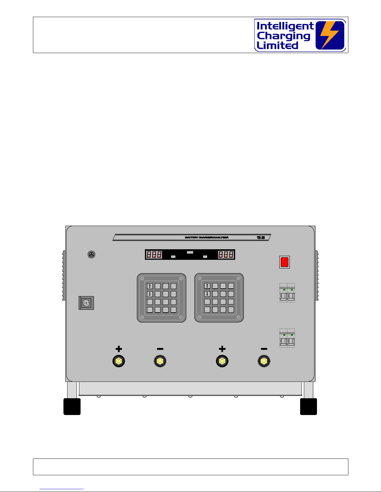
3 CONTROLS AND INDICATORS
Doc: DWG1006-34-R3 TS25 PC211 Upgrade Operators ma ual.odtPage 5 of 44 Copyright Material of Intelligent Charging Limited © 2015
Printed On : 02/09/15
AUDIBLE ALARM
MUTE
EXTD
ENTR
DISP DATA
A SET PROC
V SETTEST BATT
CHRG T SET
START
STOP
EXTD
ENTR
DISP DATA
A SET PROC
V SETTEST BATT
CHRG ONE T SET
START
STOP
VOLTS TIME
AMPS
TEST
END ONE
VOLTSTIME
AMPS
TEST
END
%
%
ALARM
MEM
Bxx
ON
OFF
I
O
MEM
Bxx
ON
OFF
I
O
MEM
Bxx
ON
OFF
I
O
MEM
Bxx
ON
OFF
I
O
I N T E L L I G E N T C H A R G I N G
CHARGE
TRIP
ANALYSER
TRIP
MAINS
POWER
BATTERY 'B'BATTERY 'A'
BATTERY 'B'BATTERY 'A'
A CHANNEL DISPLAY B CHANNEL DISPLAY
POWER SWITCH
AC POWER FUSE & INLET
B CHANNEL DATA
ENTRY KEYPAD
A CHANNEL DATA
ENTRY KEYPAD
CHANNEL A POSITIVE
BATTERY LEAD CONNECTOR
CHANNEL A NEGATIVE
BATTERY LEAD CONNECTOR
CHANNEL B NEGATIVE
BATTERY LEAD CONNECTOR
CHANNEL B POSITIVE
BATTERY LEAD CONNECTOR
CHANNEL A SAFETY CIRCUIT BREAKERS
CHANNEL B SAFETY CIRCUIT BREAKERS
MB/TS25 PC211 UPGRADE Battery Charger
Operators Manual
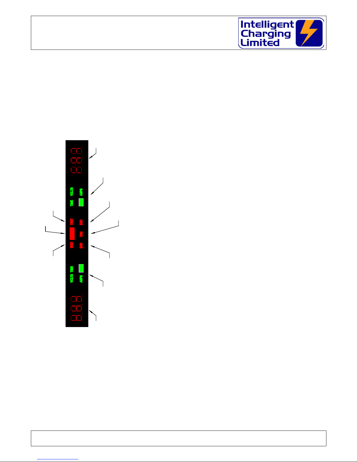
3.1DISPLAY
NUMERIC DISPL Y
oVoltage is displayed in volts to a resolution of 0.1V
oCurrent is displayed in mperes to a resolution of
0.1
oCapacity test time is displayed in minutes to a
resolution of 1 minute.
oCharge time is displayed in hours to a resolution of
0.1H (One tenth)
oBattery efficiency is displayed in percent to a
resolution of 1%.
NUMERIC DISPL Y INDIC TORS
oVOLTS illuminated means voltage is being displayed
or entered.
oMPS illuminated means current is being displayed
or entered.
oTIME illuminated means time is being displayed or
entered.
o% Illuminated means that battery efficiency is
being displayed.
oTEST illuminated means that the unit is set to
capacity test mode otherwise it is set to charge
mode.
oEND illuminated means that the unit is stopped.
oL RM illuminated means that the unit has just
stopped and the alarm has sounded.
oONE illuminated means that ONE mode has been
selected and the paralleling leads must be used.
Doc: DWG1006-34-R3 TS25 PC211 Upgrade Operators ma ual.odtPage 6 of 44 Copyright Material of Intelligent Charging Limited © 2015
Printed On : 02/09/15
%
%
ALARM
CHANNEL A NUMERIC DISPLAY CHANNLE B NUMERIC DISPLAY
CHANNEL A NUMERIC DISPLAY MODE INDICATOR CHANNEL B NUMERIC DISPLAY MODE INDICATOR
ILLUMINATED IF CAPTEST SELECTED ILLUMINATED IF CHANNEL B CAPTEST MODE IS SELECTED
ILLUMINATED IF THE CHARGER ALARM HAS SOUNDED
ILLUMINATED IF CHANNEL A IS STOPPED ILLUMINATED IF CHANNEL B IS STOPPED
ILLUMINATED IF THE "ONE" MODE OF OPERATION IS SELECTED

MB/TS25 PC211 UPGRADE Battery Charger
Operators Manual
3.2 POWER SWITCH
Operation of this switch will either apply or remove the ac inlet power from the TS25
UPGR DE
WARNING
AVOID REMOVING THE POWER FROM THE UNIT WHILE THE UNIT IS
PERFORMING A CAPACITY TEST OR CHARGE.
3.3 AUDIBLE ALARM
When a charge or capacity test has completed or stopped in error the audible alarm
will sound until the MUTE or STOP key is pressed.
3.4 CHARGE CAPACITY TEST CIRCUIT BREAKERS
The circuit breakers are fitted to prevent high currents from being driven into the
battery or into the unit should a fault condition occur. lways ensure that the circuit
breaker is in the ON position before starting a charge or capacity test.
WARNING
NEVER SWITCH THE CIRCUIT BREAK TO ON WHEN THE UNIT IS PERFORMING
A CHARGE OR CAPACITY TEST AS SEVERE DAMAGE MAY OCCUR TO THE
BATTERY OR THE TS25 UPGRADE
ALWAYS PRESS STOP FIRST
If the circuit breaker operates during a charge immediately press STOP on BOTH
charger channels and remove power from the unit and disconnect the battery.
Operation of the circuit breaker is an indication of a fault and the unit will need to be
checked before use.
3.5 BATTERY CONNECTORS
The battery terminal are where the supplied leads are connected to the TS25
UPGR DE. It is recommended that replacement leads are always purchased from
Intelligent Charging.
Doc: DWG1006-34-R3 TS25 PC211 Upgrade Operators ma ual.odtPage 7 of 44 Copyright Material of Intelligent Charging Limited © 2015
Printed On : 02/09/15

MB/TS25 PC211 UPGRADE Battery Charger
Operators Manual
3.6 KEYBOARD
Each keypad on the unit controls only information for that channel, except when the
unit is put into ONE mode both keypads control the ONE mode of operation. The only
difference is that if a data entry function is invoked in the channel B keypad the data
entry will always have to be performed on the right hand keypad. There are 16 keys
on each keypad and each key performs a particular function depending if the channel
is running or stopped.
3.6.1 STOPPED KEY MAPPING
Increases D splay Br ghness
Reduces D splay Br ghtness
Selects CHARGE MODE
Selects CAPACITY TEST MODE
2 X To Save Battery Data Into The LIBRARY
Selects A Battery From The LIBRARY
2 X Reset Parameters In The Un t Cycles Through D splayed Data
Br efly D splays Battery Data
Enters The Battery AMPS
Enters The Battery VOLTS
Enters The Battery TIME
Starts CHARGE/CAPACITY TEST
Clears The D splay And Alarm
On CHANNEL A (ONE) Selects ONE Mode
On CHANNEL B (MUTE) Stops The Aud ble Alarm
Enters The Battery MODE
EXTD
ENTR
DISP DATA
A SET PROC
V SETCHRG BATT
TEST ONE T SET
START
STOP
3.6.2 RUNNING KEY MAPPING
Increases D splay Br ghness
Reduces D splay Br ghtness
2 X To In t ate CALIBRATION
Br efly D splays Battery Number
Cycles Through D splayed Data
Br efly D splays Battery Data
Bre fly D splays The Battery AMPS
Bre fly D splays The Battery VOLTS
Br efly D splays The Battery TIME
Manually STOPS The CHARGE/CAPACITY TEST
Bre fly D splays The Battery MODE
EXTD
ENTR
DISP DATA
A SET PROC
V SETCHRG BATT
TEST ONE T SET
START
STOP
Note keys that have no comments against them do nothing while RUNNING
Doc: DWG1006-34-R3 TS25 PC211 Upgrade Operators ma ual.odtPage 8 of 44 Copyright Material of Intelligent Charging Limited © 2015
Printed On : 02/09/15

MB/TS25 PC211 UPGRADE Battery Charger
Operators Manual
4 USING THE TS25 UPGRADE
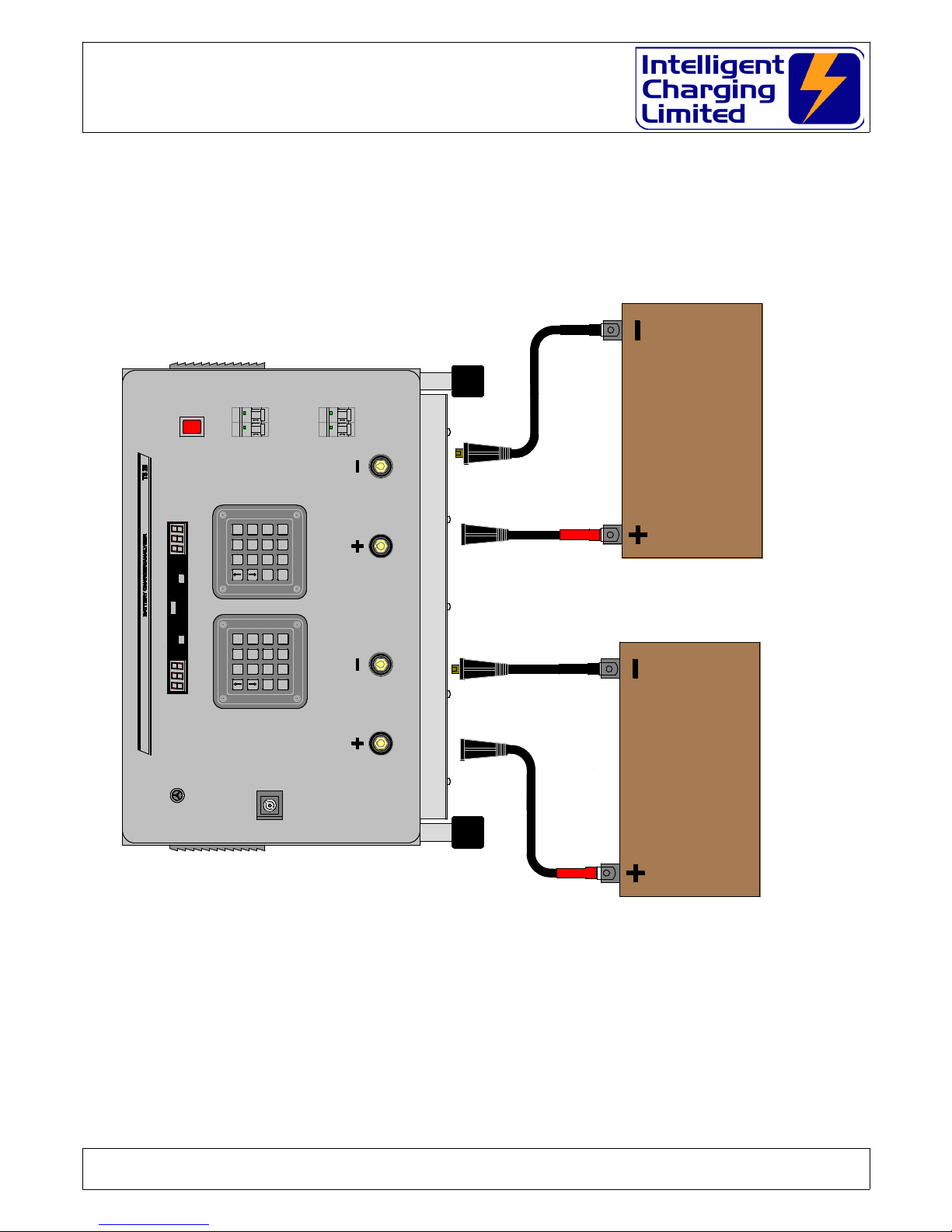
4.1 CONNECTING BATTERIES
For all methods of use of the battery charger the battery to be tested or charged must
only be connected when the charger is either:
SWITCHED OFF
or
SWITCHED ON ND END L MP ILLUMIN TED
Connecting a battery while the charge is operational would damage the equipment,
and possible draw an electrical arc that, may cause an explosion from the venting
gases being emitted from the battery.
Care must also be executed in ensuring that the bared ends of the battery leads do
not come in contact with the metalwork of the charger as this may also cause
electrical arcing and or explosion risk.
WARNING
THE BATTERY SHOULD NEVER BE CONNECTED OR DISCONNECTED FROM THE
UNIT WHEN A CHARGE OR TEST IS IN PROGRESS AS ARCING CAN OCCUR
CAUSING AN EXPLOSION FROM GASSES VENTING FROM BATTERIES BEING
PROCESSED
THE BATTERY SHOULD ALWAYS BE ISOLATED FROM ANY EQUIPMENT
BEFORE BEING CONNECTED
Stray ground loops between the attached equipment and the TS25 UPGR DE could
cause catastrophic damage to the unit and the attached equipment.
The battery or batteries must be connected to the TS25 UPGR DE as shown in the
following diagram: -
Doc: DWG1006-34-R3 TS25 PC211 Upgrade Operators ma ual.odtPage 9 of 44 Copyright Material of Intelligent Charging Limited © 2015
Printed On : 02/09/15
MB/TS25 PC211 UPGRADE Battery Charger
Operators Manual
SINGLE OR TWIN CHANNEL BATTERY CONNECTION
Doc: DWG1006-34-R3 TS25 PC211 Upgrade Operators ma ual.odtPage 10 of 44Copyright Material of Intelligent Charging Limited © 2015
Printed On : 02/09/15
AVIATION BATTERY AVIATION BATTERY
BATTERY #1 BATTERY #2
MUTE
EXTD
ENTR
DISP DATA
A SET PROC
V SETTEST BATT
CHRG T SET
START
STOP
EXTD
ENTR
DISP DATA
A SET PROC
V SETTEST BATT
CHRG ONE T SET
START
STOP
VOLTS TIME
AMPS
TEST
END ONE
VOLTSTIME
AMPS
TEST
END
%
%
ALARM
MEM
Bxx
ON
OFF
I
O
MEM
Bxx
ON
OFF
I
O
MEM
Bxx
ON
OFF
I
O
MEM
Bxx
ON
OFF
I
O
I N T E L L I G E N T C H A R G I N G
CHARGE
TRIP
ANALYSER
TRIP
MAINS
POWER
BATTERY 'B'BATTERY 'A'
BATTERY 'B'BATTERY 'A'

MB/TS25 PC211 UPGRADE Battery Charger
Operators Manual
BATTERY CONNECTION WHEN USING “ONE” MODE OF OPERATION
Doc: DWG1006-34-R3 TS25 PC211 Upgrade Operators ma ual.odtPage 11 of 44Copyright Material of Intelligent Charging Limited © 2015
Printed On : 02/09/15
AVIATION BATTERY
MUTE
EXTD
ENTR
DISP DATA
A SET PROC
V SETTEST BATT
CHRG T SET
START
STOP
EXTD
ENTR
DISP DATA
A SET PROC
V SETTEST BATT
CHRG ONE T SET
START
STOP
VOLTS TIME
AMPS
TEST
END ONE
VOLTSTIME
AMPS
TEST
END
%
%
ALARM
MEM
Bxx
ON
OFF
I
O
MEM
Bxx
ON
OFF
I
O
MEM
Bxx
ON
OFF
I
O
MEM
Bxx
ON
OFF
I
O
I N T E L L I G E N T C H A R G I N G
CHARGE
TRIP
ANALYSER
TRIP
MAINS
POWER
BATTERY 'B'BATTERY 'A'
BATTERY 'B'BATTERY 'A'

MB/TS25 PC211 UPGRADE Battery Charger
Operators Manual
4.2 CAPACITY TESTING BATTERIES
The main purpose of a capacity test is to establish that a battery under test can
maintain current output as specified by its ampere hour rating above a certain
terminal voltage.
s a rule of thumb a battery will maintain an output voltage 5/6ths above its terminal
voltage for one hour if discharged at its ampere hour rating. battery that can
maintain this is considered 100% or more of its rated capacity.
For example a 24V 20 /H battery would be capacity tested at 20 for one hour and
have the voltage end point set to 20V. If after a one hour discharge at 20 the battery
terminal voltage was greater than 20V the battery would be considered at least 100%
efficient.
Intelligent Charging do not make any recommendations on what point a battery is
considered not efficient enough to be used, although a rule of thumb is that a battery
less than 80% should be discarded where it it's use is considered critical.
The TS25 UPGR DE has two capacity test modes: -
Perform a capacity test only to the time period specified.
This mode will auto terminate the process if either the battery voltage reaches
the voltage end point, or if the total capacity test time is achieved. t the end of
the test the TS25 UPGR DE will report a percentage of 100% or less depending
on why the capacity test was terminated.
Perform a capacity test until the final voltage is reached.
This mode will perform a capacity test until the voltage end point is reached. t
the end of test the TS25 UPGR DE will report a percentage, which is the true
capacity of the battery, which may be more than 100%. This method is
sometimes employed so that records of battery deterioration over time or use
can be monitored.
4.2.1 MANUAL CAPACITY TEST
To perform a manual capacity test four parameters have to be programmed.
These are: -
Capacity test current ( mperes).
Capacity test time (Minutes)
Capacity test voltage end point (Volts)
Capacity test mode (Time or Volts)
To program these values the TS25 UPGR DE needs to powered and not
performing either a capacity test or charge on the channel to be used.
Doc: DWG1006-34-R3 TS25 PC211 Upgrade Operators ma ual.odtPage 12 of 44Copyright Material of Intelligent Charging Limited © 2015
Printed On : 02/09/15

MB/TS25 PC211 UPGRADE Battery Charger
Operators Manual
Press ASET to change the capacity test amperes.
Press VSET to change the capacity test voltage end point.
Press TSET to change the capacity test duration.
Press PROC to change the capacity test mode.
See section 4.4 ENTERING B TTERY D T for details on how to enter the
required parameters.
4.2.2 LIBRARY CAPACITY TEST
To perform a capacity test from the library the library number has to be selected
first. To select the library number the following procedure has to be performed.
Press the BATT key. The display will show the current library item selected and
the rightmost digit will be flashing. Enter the library number by using the and
keys and the EXTD key to move to the next digit. Only library numbers 01 to
99 can be selected.
The TS25 UPGR DE needs to be placed in capacity test mode by pressing TEST
and ensuring that the visual indicator TEST is illuminated.
4.2.3 REVIEWING CAPACITY TEST PARAMETERS
Once these values have been programmed into the unit they can be reviewed by
selecting the DISP key to cycle the display between VOLTS, AMPS,TIME and
% and then pressing the DATA key. This display will show the values
programmed in and the corresponding indicator will flash. Note when the %
indicator is lit there is no data to display. To check the capacity test mode simple
press the TEST key and the current capacity test mode will be displayed TIM or
VOL.
4.2.4 STARTING A CAPACITY TEST
Before a capacity test is performed for the first time it is important that the
parameters are reviewed using the reviewing feature above as incorrect
parameters could damage the battery under test.
Once satisfied that he data is correct the battery to undergo the capacity test
must be connected to the unit. Care must be taken when connecting batteries
which are not fitted with non reversible connectors, i.e. where the use of
crocodile clamps are implemented, as damage to the battery and or unit may
occur if a capacity test is started with reverse connection.
To begin the capacity test press START. The display will momentarily display
RUN, the END light will extinguish and it will then display battery voltage. During
the normal capacity test process the DISP key may be pressed to cycle the
display between VOLTS, AMPS,TIME and %. The DATA key can also be
pressed to review the parameters programmed in for the current test under
progress. If the TEST key is pressed this will briefly display the current test
mode.
Doc: DWG1006-34-R3 TS25 PC211 Upgrade Operators ma ual.odtPage 13 of 44Copyright Material of Intelligent Charging Limited © 2015
Printed On : 02/09/15

MB/TS25 PC211 UPGRADE Battery Charger
Operators Manual
4.2.5 STOPPING A CAPACITY TEST
t any time during the capacity test the process can be terminated by simply
pressing the STOP key. When the STOP key is pressed the process will be
terminated immediately and the display will show END and the END led will
remain illuminated.
The display will remain in this state until either MUTE of STOP is pressed.
4.2.6 CAPACITY TEST AUTO TERMINATE
If the capacity test has been programmed to auto terminate on time then the
process will automatically stop when either the battery voltage falls below the
voltage end point or when the capacity test time has elapsed.
If the capacity test has been programmed to auto terminate only when the
voltage falls below the voltage end point, then the process will stop when the
battery voltage falls below the voltage end point.
In both cases the capacity test process will terminate immediately, the audible
alarm will sound and the ALARM and END lights will illuminate and the display will
show the reason for terminating the process.
To clear the alarm the MUTE or STOP key must be pressed. Upon these being
pressed the display will show the actual efficiency percent value.
Process termination codes:
E 1 The process time is complete.
E 2 Battery voltage has reached the voltage end point.
Doc: DWG1006-34-R3 TS25 PC211 Upgrade Operators ma ual.odtPage 14 of 44Copyright Material of Intelligent Charging Limited © 2015
Printed On : 02/09/15

MB/TS25 PC211 UPGRADE Battery Charger
Operators Manual
4.3 CHARGING BATTERIES
To keep batteries in good condition it is important that correct charging procedures
are observed.
The TS25 UPGR DE is an important tool in ensuring the its flexibility allows the user to
choose charge processes that are best suited to the battery. The TS25 UPGR DE has
two inbuilt charging processes that suite a wide range of batteries.
The use of constant voltage charging is best suited to lead acid types of batteries and
the TS25 UPGR DE controls constant voltage charging to ensure that no excess of
current can be driven into the batteries causing it damage.
Constant voltage charging is achieved by inserting a maximum specified current into a
battery until its terminal voltage reached the voltage set point. Once this voltage set
point has been reached the unit will reduce the current injected to maintain the
voltage set point. The charging process will continue until the charge time has
elapsed.
Constant current charging is employed mainly for Nickel Cadmium and Nickel Metal
hydride types if batteries, where a constant current can be driven into a battery for a
specified time and parameters can be set to prevent over charging.
Constant current charging is achieved by the unit driving a specified constant current
into the battery for a specified amount of time. During this time it will monitor the
battery voltage and auto terminate the process if this voltage is reached. This voltage
set point can be either the rise point of the battery or can be used as an over-voltage
parameter.
The TS25 UPGR DE has a new charge mode implemented, which is more suitable to
alkaline batteries. In this mode known as Constant Current Plus mode the unit will
drive the constant current into the battery until the voltage set point is reached. Once
this point is reached the unit will continue charging at the same current for the time
specified.
4.3.1 MANUAL CHARGING
The unit required four parameters to perform a constant voltage charge. These
are: -
Maximum charge current ( mperes).
Charge time or charge additional time (Hours).
Voltage set point (Volts).
Charge mode.
To program these values the unit needs to powered and not performing either a
capacity test or charge on the channel to be used.
Press ASET to change the charge amperes.
Press VSET to change the charge test voltage set point.
Press TSET to change the charge duration or additional time.
Doc: DWG1006-34-R3 TS25 PC211 Upgrade Operators ma ual.odtPage 15 of 44Copyright Material of Intelligent Charging Limited © 2015
Printed On : 02/09/15

MB/TS25 PC211 UPGRADE Battery Charger
Operators Manual
Press PROC to change the charge mode.
See section 4.4 ENTERING B TTERY D T for details on how to enter the
required parameters.
4.3.2 LIBRARY CHARGING
To perform a charge from the library the library number has to be selected first.
To select the library number the following procedure has to be performed.
Press the BATT key. The display will show the current library item selected and
the rightmost digit will be flashing. Enter the library number by using the and
keys and the EXTD key to move to the next digit. Only library numbers 01 to
99 can be selected.
The unit needs to be placed in charge mode by pressing CHRG and ensuring that
the visual indicator TEST is extinguished.
4.3.3 REVIEWING CHARGE PARAMETERS
Once these values have been programmed into the unit they can be reviewed by
selecting the DISP key to cycle the display between VOLTS, AMPS and TIME
and then pressing the DATA key. This display will show the values programmed
in and the corresponding indicator will flash. To check the charge mode simply
press the CHRG key and the current charge mode will be displayed CV, CC or
CCA.
4.3.4 STARTING A CHARGE
Before a charge is performed for the first time it is important that the parameters
are reviewed using the reviewing feature above as incorrect parameters could
damage the battery under charge.
Once satisfied that he data is correct the battery to undergo charging must be
connected to the unit. Care must be taken when connecting batteries which are
not fitted with non reversible connectors, i.e. where the use of crocodile clamps
are implemented, as damage to the battery and or TS25 UPGR DE may occur if
a charge is started in reverse connection.
To begin the charge press START. The display will momentarily display RUN, the
END light will extinguish and it will then display battery voltage. During the
normal charge process the DISP key may be pressed to cycle the display
between VOLTS, AMPS and TIME. The DATA key can also be pressed to review
the parameters programmed in for the current test under progress. Pressing the
CHRG key will also briefly display the current charge mode.
4.3.5 STOPPING A CHARGE
t any time during the charge the process can be terminated by simply pressing
the STOP key. When the STOP key is pressed the process will be terminated
Doc: DWG1006-34-R3 TS25 PC211 Upgrade Operators ma ual.odtPage 16 of 44Copyright Material of Intelligent Charging Limited © 2015
Printed On : 02/09/15

MB/TS25 PC211 UPGRADE Battery Charger
Operators Manual
immediately and the display will show END and the END led will remain
illuminated.
The display will remain in this state until either MUTE of STOP is pressed.
4.3.6 CHARGE PROCESS AUTO TERMINATE
If constant voltage charging the process will automatically stop when the test
time has been completed.
If constant current charging is programmed then the charge will terminate on the
full charge time completed or if the battery terminal voltage reached the voltage
set point.
If constant current with additional time mode is being performed then the unit
will stop when the additional time has been used or if the voltage set point is not
reached within 24 hours of the charge starting.
In all cases the charge process will terminate immediately, the audible alarm will
sound and the ALARM and END lights will illuminate and the display will show the
reason for terminating the process.
To clear the alarm the MUTE or STOP key must be pressed.
Process termination codes:
E 1 The process time or additional time is complete.
E 3 Voltage set point reached (Constant Current Mode Only).
E 4 The voltage set point has not been reached within 24Hours.
Doc: DWG1006-34-R3 TS25 PC211 Upgrade Operators ma ual.odtPage 17 of 44Copyright Material of Intelligent Charging Limited © 2015
Printed On : 02/09/15

MB/TS25 PC211 UPGRADE Battery Charger
Operators Manual
4.4 ENTERING BATTERY DATA
In all cases of entering battery data the channel that data is to be entered on must be
in the stopped state. This is indicated by the END lamps being illuminated.
4.4.1 SETTING CAPACITY TEST MODE
Press PROC the display will flash the current mode on the display. Using the
and arrow keys the flashing display can be changed from TIM to VOL and visa
versa. Once selection has been made the ENTR key will be pressed to program
this parameter into the unit. If no change is required then simply pressing STOP
will clear the display.
TIM Programs the capacity testing mode to auto terminate when the battery
voltage falls below the voltage end point or when the time up has been
reached.
VOL Programs the capacity testing mode to only auto terminate when the
voltage end point has been reached.
4.4.2 SETTING THE CHARGE MODE
Press PROC the display will flash the current mode on the display. Using the
and arrow keys the flashing display can be changed from CV, CC and CCA and
visa versa. Once selection has been made the ENTR key will be pressed to
program this parameter into the unit. If no change is required then simply
pressing STOP will clear the display.
CV Programs the charge mode to perform a constant voltage charge where the
charge current is not exceeded until the voltage set point is reached at
which point it reduces current to maintain the voltage set point until the
charge time is completed.
CC Programs the charge mode to perform constant current charging for the
time specified terminating abnormally if the voltage set point is reached.
CCA Programs the charge mode to perform constant current charging until the
voltage set point is reached and then continue charging at the same current
until the additional time has elapsed.
4.4.3 ENTERING CURRENT DATA
Press the ASET key. The current setting will be displayed. The rightmost digit will
be flashing and can be modified by pressing the and arrow keys. Pressing
the EXTD key will cause the middle digit to flash and this can then be modified by
using the and arrow keys. Pressing the EXTD key again will cause the
leftmost digit to flash and this can then be modified using the and arrow
keys. If the EXTD key is pressed again the rightmost digit will then flash. This
cycle is repeated each time the EXTD key is pressed. The values cannot be
Doc: DWG1006-34-R3 TS25 PC211 Upgrade Operators ma ual.odtPage 18 of 44Copyright Material of Intelligent Charging Limited © 2015
Printed On : 02/09/15

MB/TS25 PC211 UPGRADE Battery Charger
Operators Manual
modified to greater than 12.0 for charge mode and 25.0 for capacity test
mode.
Note: In ONE mode the maximum values that can be entered are 24.0 for
charge mode and 50.0 for capacity test mode.
4.4.4 ENTERING VOLTAGE DATA
Press the VSET key. The current setting will be displayed. The rightmost digit will
be flashing and can be modified by pressing the and arrow keys. Pressing
the EXTD key will cause the middle digit to flash and this can then be modified by
using the and arrow keys. Pressing the EXTD key again will cause the
leftmost digit to flash and this can then be modified using the and arrow
keys. If the EXTD key is pressed again the rightmost digit will then flash. This
cycle is repeated each time the EXTD key is pressed. The voltage value to be
entered cannot exceed 45.0V and the display will not allow digits to be
incremented above this amount.
4.4.5 ENTERING CAPACITY TEST TIME
Press the TSET key. The current setting will be displayed. The rightmost digit will
be flashing and can be modified by pressing the and arrow keys. Pressing
the EXTD key will cause the middle digit to flash and this can then be modified by
using the and arrow keys. Pressing the EXTD key again will cause the
leftmost digit to flash and this can then be modified using the and arrow
keys. If the EXTD key is pressed again the rightmost digit will then flash. This
cycle is repeated each time the EXTD key is pressed. The value entered is in
minutes and the maximum time that can be entered is 999 minutes.
4.4.6 ENTERING CHARGE TIME
Press the VSET key. The current setting will be displayed. The rightmost digit will
be flashing and can be modified by pressing the and arrow keys. Pressing
the EXTD key will cause the middle digit to flash and this can then be modified by
using the and arrow keys. Pressing the EXTD key again will cause the
leftmost digit to flash and this can then be modified using the and arrow
keys. If the EXTD key is pressed again the rightmost digit will then flash. This
cycle is repeated each time the EXTD key is pressed. The value entered is in
hours and the maximum time than can be entered in 99.9H.
Doc: DWG1006-34-R3 TS25 PC211 Upgrade Operators ma ual.odtPage 19 of 44Copyright Material of Intelligent Charging Limited © 2015
Printed On : 02/09/15

MB/TS25 PC211 UPGRADE Battery Charger
Operators Manual
4.5 USING THE ONE MODE OF OPERATION
The TS25MKII has a special feature in that if higher currents for charging or capacity
testing are required the unit can be "paralleled". Using special paired cables, which
connect, channel and channel B together both channels can be used in unison.
WARNING
PAY CAREFUL ATTENTION TO BATTERY CONNECTION
WHEN USING “ONE” MODE
Control of the unit is all achieved through the use of the channel keypad and the
channel B keypad only mimics some of the channel functions. The channel B display
will change to an alternative display to channel when the DISP key is pressed.
ll operation of the equipment is the same as when using an individual channel, with
the exception that higher currents can be entered for capacity testing and charging.
If a library item has been written in one mode, it will only be recalled in ONE mode if
the current exceeds the single channel limitations of the unit.
Certain actions cannot be performed in ONE mode and these are reported on the
display in the form of an error message and buzzer sound.
4.6 RESETTING THE TS25 UPGRADE
The TS25 UPGR DE keeps users modified data in battery backed R M. It may be
necessary at some time to reset this data to the defaults. Three sets of data can be
reset.
4.6.1 GENERAL PARAMETER DATA
The general parameter data covers the current battery data that is set and
indicators to general unit operation. It is not usually necessary to reset this data
as is checked internally for correctness, but when the unit has been serviced and
the battery backup removed the general parameter data can be come corrupt
and may need resetting through the use of this function.
4.6.2 DEFAULT LIBRARY DATA
The operator may want at some time to reset the internal data library back to
the default battery library, this function copies the internal library into the user
definable battery library. Warning: The use of this function will remove all user
defined library items.
Doc: DWG1006-34-R3 TS25 PC211 Upgrade Operators ma ual.odtPage 20 of 44Copyright Material of Intelligent Charging Limited © 2015
Printed On : 02/09/15
Table of contents
Other Intelligent Charging Batteries Charger manuals


