Intelligent Charging IC8P User manual
IC8P Battery Charger/Analyser
Operator Manual
Doc: DWG1062-06-R3 IC8P Operators manual.odt Pa e 1 of 46 Copyright Material of Intelligent Charging Limited © 2018
Printed On : 20/11/19
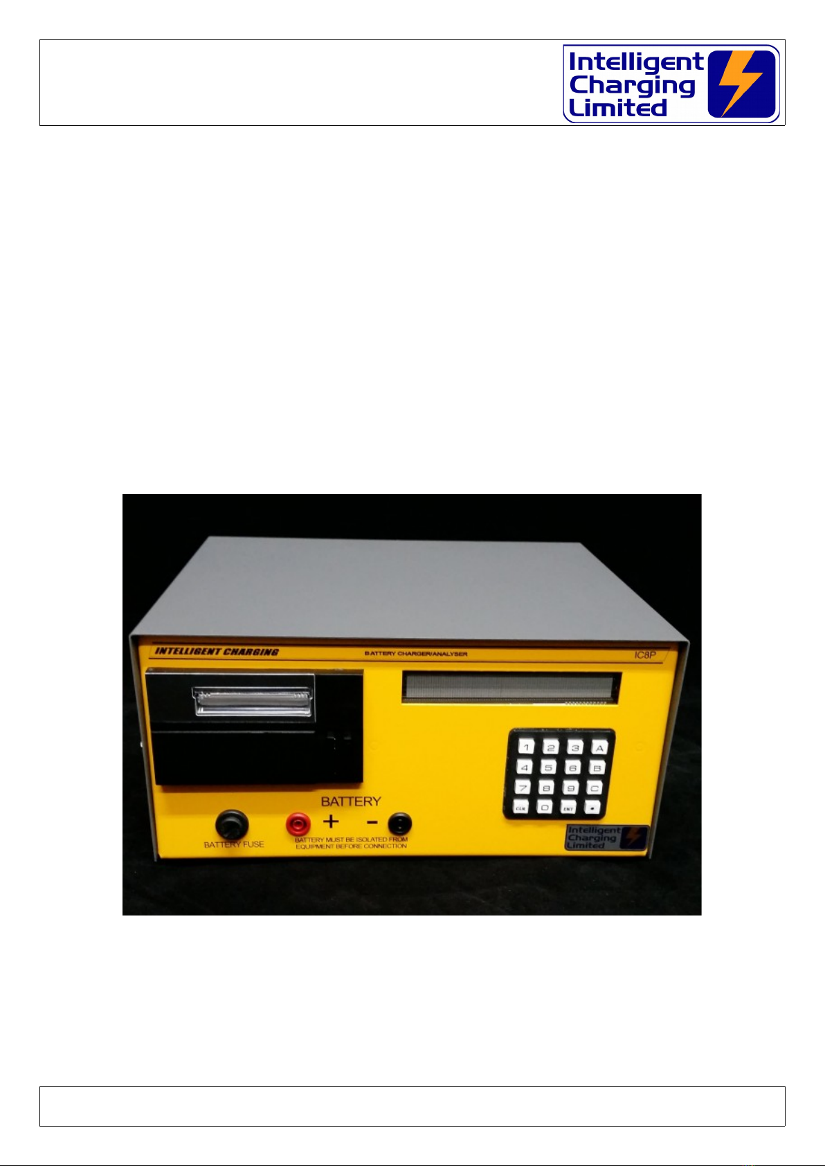
IC8P
BATTERY CHARGER/ANALYSER
OPERATORS MANUAL

IC8P Battery Charger/Analyser
Operator Manual
Table of Contents
1 Manual Revision History...........................................................................................................4
2 Equipment Description.............................................................................................................5
2.1 General............................................................................................................................5
2.1.1 Charging Mo es.........................................................................................................6
2.1.2 Capacity Testing Mo es..............................................................................................6
2.2 Component Parts..............................................................................................................7
2.3 Installation.......................................................................................................................7
2.4 Front Controls An In icators............................................................................................8
2.5 Rear Controls An In icators.............................................................................................9
3 Equipment Menu Operation....................................................................................................10
3.1 Charging Menu................................................................................................................10
3.2 Capacity Testing Menu....................................................................................................11
3.3 Process Operation Menu..................................................................................................12
3.4 Settings Menu.................................................................................................................14
4 Connecting A Battery.............................................................................................................15
5 Battery Charge Operation.......................................................................................................17
5.1 Constant Voltage Charge.................................................................................................17
5.2 Constant Current Charge.................................................................................................18
5.3 Multi-Step Constant Current Charge.................................................................................19
5.3.1 CHARGE FROM A LIBRARY ENTRY.............................................................................20
5.3.2 CHARGE FROM MANUAL DATA..................................................................................20
5.3.3 CHARGE FROM PREVIOUS DATA...............................................................................20
6 Battery Capacity Test or Discharge Operation..........................................................................21
6.1 Capacity Test To 100%...................................................................................................21
6.2 Capacity Test To Target Voltage......................................................................................22
6.3 Full Battery Discharge......................................................................................................23
6.4 Performing A Capacity Test..............................................................................................24
6.4.1 Capacity Test or Discharge From A Library Entry........................................................24
6.4.2 Capacity Test or Discharge From Manual Data............................................................24
6.4.3 Capacity Test or Discharge From Previous Data..........................................................24
7 Creating Or Mo ifying Library Entries......................................................................................24
7.1 Data Entry Proce ure......................................................................................................25
7.2 Entering Charge Data......................................................................................................25
7.3 Entering Discharge Data..................................................................................................28
8 Process Mo e........................................................................................................................30
8.1 Overview Of Operation....................................................................................................30
8.2 Process Menu..................................................................................................................30
8.2.1 Renaming a process.................................................................................................31
8.2.2 View or E it A Process..............................................................................................31
8.3 Process Execution...........................................................................................................31
8.4 Process Termination........................................................................................................32
9 Calibration.............................................................................................................................33
9.1 Equipment Require ........................................................................................................33
Doc: DWG1062-06-R3 IC8P Operators manual.odt Pa e 2 of 46 Copyright Material of Intelligent Charging Limited © 2018
Printed On : 20/11/19

IC8P Battery Charger/Analyser
Operator Manual
9.2 Calibration Equipment Connection....................................................................................33
9.3 Check Proce ure.............................................................................................................33
9.4 Making Calibration A justment.........................................................................................34
9.5 Reviewing Calibration Date..............................................................................................35
9.6 Setting the lea volt rop................................................................................................35
10 Miscellaneous Unit Functions.................................................................................................36
10.1 Description Of Stop Co es.............................................................................................36
10.2 Print Or Display Previous Operation Results.....................................................................38
10.3 Changing The Date Format An Date Time.....................................................................38
10.4 Mo ifying Display Intensity............................................................................................39
10.5 Automatic screen im....................................................................................................39
10.6 Printing battery serial number (IC8P)..............................................................................39
10.7 Cooling Fan...................................................................................................................39
11 Service An Maintenance......................................................................................................40
11.1 Calibration....................................................................................................................40
11.2 Cleaning.......................................................................................................................40
11.3 Battery Backup..............................................................................................................40
11.4 Printer Care..................................................................................................................41
11.4.1 Door Latch.............................................................................................................41
11.4.2 Paper Fee Button..................................................................................................41
11.4.3 Paper Roll Replacement..........................................................................................42
11.4.4 Ribbon Cartri ge Replacement................................................................................42
11.4.5 Consumables Available............................................................................................43
12 Specifications.......................................................................................................................44
13 Pro uct Disposal Instructions................................................................................................45
14 Pro uct Warranty.................................................................................................................46
Doc: DWG1062-06-R3 IC8P Operators manual.odt Pa e 3 of 46 Copyright Material of Intelligent Charging Limited © 2018
Printed On : 20/11/19

IC8P Battery Charger/Analyser
Operator Manual
1 Manual Revision History
Rev Date Description
1 28-04-2014 Adapted from Issue 3 IC8A Manual and added printer content.
2 21-07-2015 Formattin chan es.
3 20-11-2019 Updated drawin s and incorporated new functions from MB.
Doc: DWG1062-06-R3 IC8P Operators manual.odt Pa e 4 of 46 Copyright Material of Intelligent Charging Limited © 2018
Printed On : 20/11/19

IC8P Battery Charger/Analyser
Operator Manual
Equipment Description
.1 General
The Battery Charger Analyser is an electronically controlle combine universal battery
charging unit with built in battery analysing (capacity testing) capabilities. It is house
in a metal enclosure esigne for bench mounting. As it is supplie it is configure for
use from a 240V 50/60Hz supply, it can be alternatively supplie for use with 115V
50/60Hz supply.
Equipment control is via an interactive 253 x 32 ot matrix isplay an ata entry is via
a 16-key keypa . Operating mo es an functions are selecte by the use of a simple
menu system. Access to charging an testing operations is performe by either entry of
eight igit battery library names, repeat of last charge or capacity test or new manual
parameters. During operation the isplay will show the instantaneous values of battery
voltage, current an time elapse through the selecte program.
Process mo es can be create where complete unatten e charging, capacity testing
an final charging can be performe . Up to 6 ifferent charge or capacity test steps can
be create an up to 4 process programs can be store in the unit. Each process step
has an optional elaye start for resting the battery an also each step can soun the
alarm with or without a pause in operation. The process is simply continue by pressing
a key on the keypa .
Battery ata is store internally in the units non-volatile memory. The operator can a
an mo ify this list by entering the etails of the battery to be inclu e on the isplay
an keyboar . Alphanumeric igits, up to a maximum of 8 igits, i entify Battery library
entries
Batteries are connecte to the front of the unit by means of two stan ar 4.0mm
sockets. A set of 500mm lea s are supplie with 4.0mm insulate plus an a pair of
4.0mm sockete croco ile clamps.
The IC8A can Charge 12V at 12.0A or 24V at 6.0A an can Capacity Test 12V at 12.0A
or 24V at 6.0A. The unit contains a fan to extract the heat energy generate internally
when running in capacity test mo e.
Doc: DWG1062-06-R3 IC8P Operators manual.odt Pa e 5 of 46 Copyright Material of Intelligent Charging Limited © 2018
Printed On : 20/11/19
IC8P Battery Charger/Analyser
Operator Manual
.1.1 Charging Modes
CONSTANT VOLTAGE CHARGE
Where the battery is charge at a re ucing current when the constant voltage
threshol is met. Parameters for this mo e are maximum charge time, optional
minimum current to stop charge an a current threshol , which can etect a
potentially faulty battery.
CONSTANT CURRENT CHARGE WITH TOP UP CHARGE
Where battery is charge at a constant current until a terminal voltage is met, at
this point it can be charge for an a itional time at a user set current. The
overcharge voltage is set in this mo e to prevent overcharging of the battery.
MULTIPLE STEP CONSTANT CURRENT CHARGE
Up to 4 constant current steps can be implemente for the charge cycle. this
mo e also has an overcharge voltage setting to prevent overcharging of the
battery. Charge current can be set to zero for “rest” perio s between charge
steps.
.1. Capacity Testing Modes
CAPACITY TEST TO 100 PERCENT
This mo e will ischarge the battery connecte at the current specifie for the
test uration specifie thus reporting the battery capacity is 100% or more. The
capacity test will be stoppe if the target voltage is reache before the full test
time has elapse . During the capacity test an when it is terminate the isplay
will show the amount the capacity test is complete as a percentage.
CAPACITY TEST TO TARGET VOLTAGE
This mo e will ischarge the battery own to the terminal voltage specifie thus
reporting the actual percentage capacity. The capacity test will be stoppe if the
target threshol voltage is reache before the full test time has elapse . During
the capacity test an when it is terminate the isplay will show the amount the
capacity test is complete as a percentage.
FULL DISCHARGE
This mo e will o a basic ischarge of the battery at the current specifie for the
time specifie .
The unit can be set so that a pre efine charge or capacity test can be sche ule to start at
up to 99h 99m in the future. An if uring this time the power is lost to the unit, such as a
power outage, the unit will continue to count own when the power is restore . Note: If the
power outage resumes after the elapse time has been passe the pre efine charge or
capacity test will not be execute .
The unit contains the software that will allow it to be calibrate by the en user oing away
with the nee to sen the unit to a service centre for perio ic calibration. The re-calibration
process only takes a few minutes an this is one without the nee to access the internals of
the unit.
Doc: DWG1062-06-R3 IC8P Operators manual.odt Pa e 6 of 46 Copyright Material of Intelligent Charging Limited © 2018
Printed On : 20/11/19

IC8P Battery Charger/Analyser
Operator Manual
. Component Parts
Upon receipt of your new battery charger analyser unpack an check that all items are
present in the containing box.
STANDARD ITEMS
One IC8P Battery Charger Analyser
One IEC power cor
One Set (+ve & -ve) stan ar battery lea s.
One pair croco ile clamps.
One paper Copy Operators Manual
Certificate Of Conformity
Calibration Certificate
.3 Installation
The Battery Charger Analyser shoul be mounte on a level surface such as a
workbench or stur y shelf above the batteries with a loa ing weight of at least 5Kg.
The unit shoul be site so that at least 5cm of airspace is available all roun the si es
an top of the unit to allow free movement of air require for cooling.
Doc: DWG1062-06-R3 IC8P Operators manual.odt Pa e 7 of 46 Copyright Material of Intelligent Charging Limited © 2018
Printed On : 20/11/19
Intelligent
Charging
Limited
1
7
4
CLR
2
5
0
8
3
6
9
ENT
A
B
C
.
16A QB
IC8P
** SERVICEABLE **
24 Jun 2015 14:01 o
CHARGE
CAPTEST
SETTINGS
LIBRARY
A
C
B
.
Bat 12.0V
INTELLIGENT CHARGING LIMITED
BATTERY CHARGER & CAPACITY TESTER IC8P
BATTERY MUST BE ISOLATED FROM
EQUIPMENT BEFORE CONNECTION
BATTERY
BATTERY FUSE
5 cm 5 cm
5 cm
IC8P Battery Charger/Analyser
Operator Manual
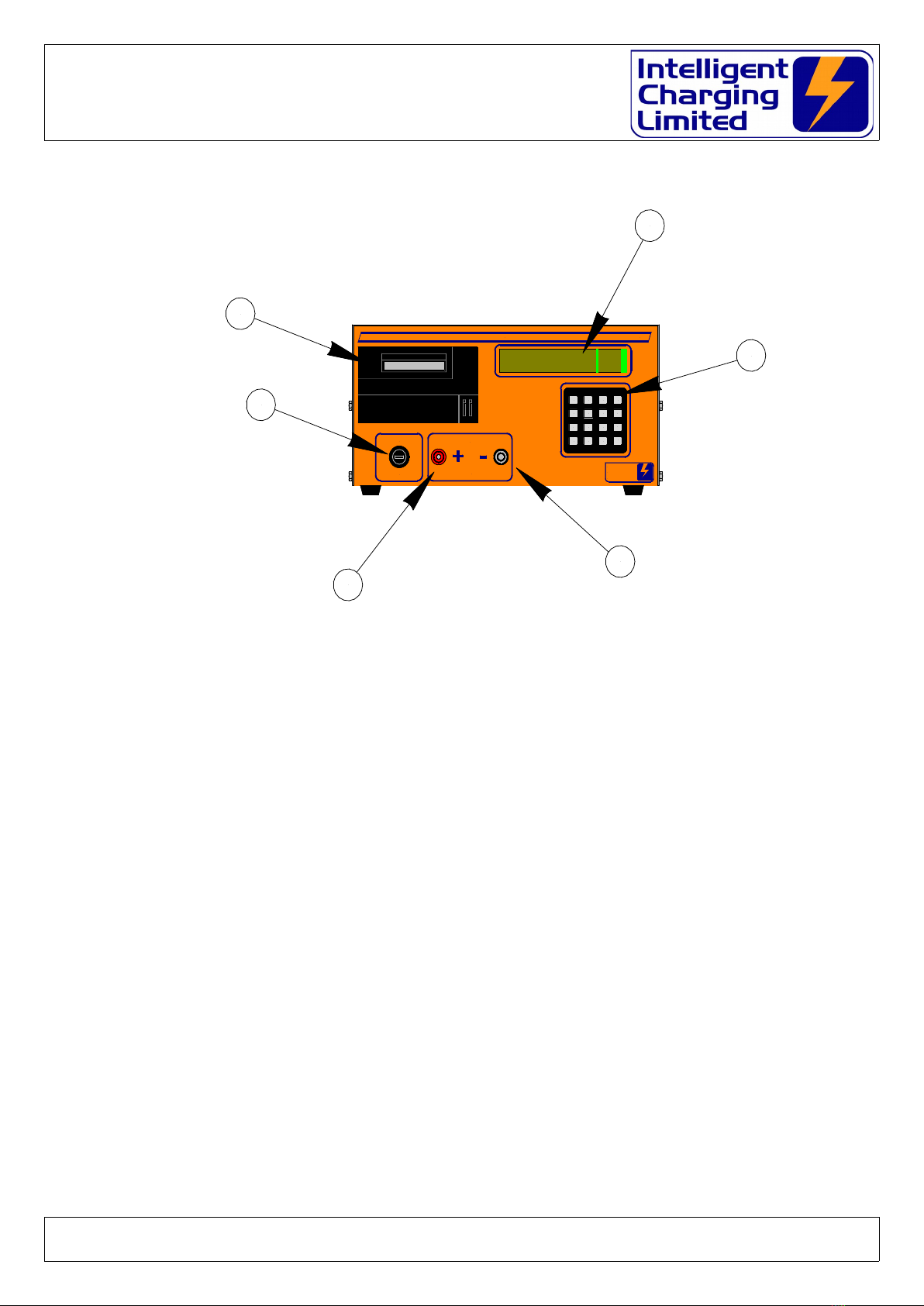
.4 Front Controls And Indicators
(A) – DISPLAY
All battery charger in ications are ma e on this 256 x 32 ot matrix vacuum fluorescent
isplay.
(B) – KEYPAD
All battery charge an capacity test functions are activate via this 16 key keypa .
(D) - NEGATIVE BATTERY TERMINAL
Connection of the negative battery lea is ma e to this terminal.
(E) - POSITIVE BATTERY TERMINAL
Connection of the positive battery lea is ma e to this terminal.
(F) – BATTERY PROTECTION FUSE
Fitte here is a 16.0A QB 1 1/4” fuse which is fitte to break if excessive or reverse
currents are etecte . If the fuse breaks uring a charge or capacity test imme iately
press STOP an remove power from the unit an isconnect the battery. Failure of the
fuse is an in ication of a fault an the unit will nee to be checke before using.
(G) – DOT MATRIX PRINTER
Fitte here is the 24 column ot matrix report printer.
Doc: DWG1062-06-R3 IC8P Operators manual.odt Pa e 8 of 46 Copyright Material of Intelligent Charging Limited © 2018
Printed On : 20/11/19
Intelligent
Charging
Limited
1
7
4
CLR
2
5
0
8
3
6
9
ENT
A
B
C
.
16A QB
IC8P
** SERVICEABLE **
24 Jun 2015 14:01 o
CHARGE
CAPTEST
SETTINGS
LIBRARY
A
C
B
.
Bat 12.0V
INTELLIGENT CHARGING LIMITED
BATTERY CHARGER & CAPACITY TESTER IC8P
BATTERY MUST BE ISOLATED FROM
EQUIPMENT BEFORE CONNECTION
BATTERY
BATTERY FUSE
A
C
D
F
B
E
IC8P Battery Charger/Analyser
Operator Manual
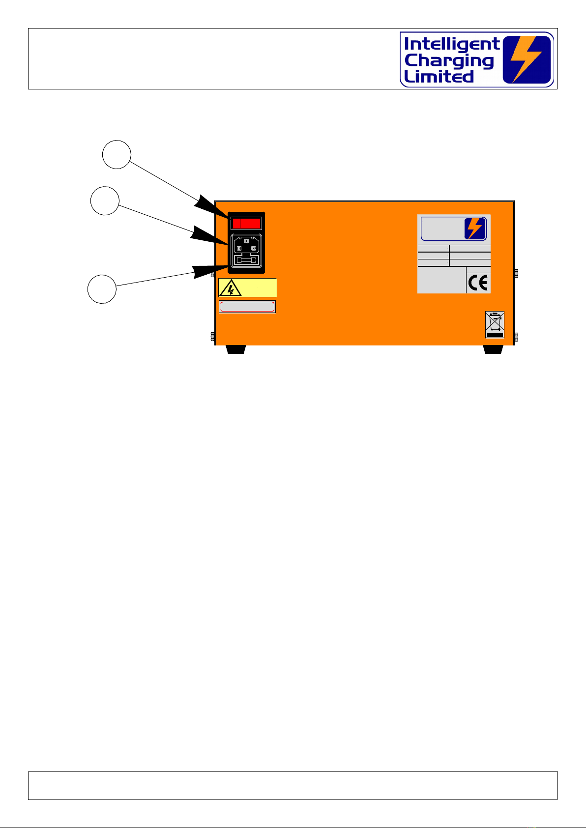
.5 Rear Controls And Indicators
(G) – PROTECTION FUSE
Mains protection fuse. 20.0mm 3.15A Slow Blow.
(H) – IEC POWER INLET
The IEC main input plug is inserte here.
(I) - POWER SWITCH
Operation of this switch applies or removes mains power from the battery charger.
Doc: DWG1062-06-R3 IC8P Operators manual.odt Pa e 9 of 46 Copyright Material of Intelligent Charging Limited © 2018
Printed On : 20/11/19
SERIAL No:
Intelligent Charging Limited
Ford House, Dewin Road,
Rackheath Ind. Est. Norwich,
Norfolk, NR13 6PS, ENGLAND.
TEL: 44-1603-722770
FAX: 44-1603-722771
MAIL: sales@intelligent-charging.com
MODEL :
P/N :
MADE IN ENGLAND
Intelligent
Charging
Limited
240V AC
240V 50Hz FUSE RATING 3.15A SB
FRONT FUSE 16.0A ANTISURGE
H
I
G

IC8P Battery Charger/Analyser
Operator Manual
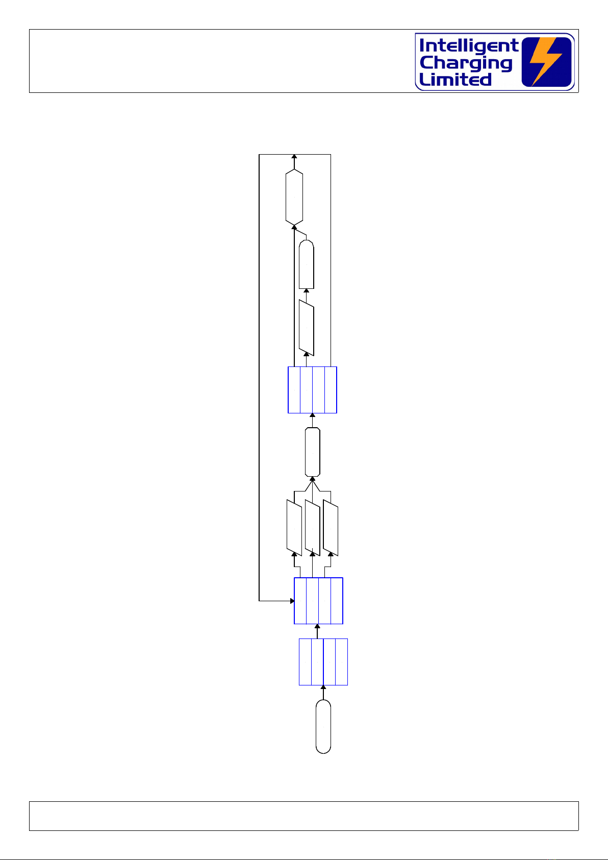
3 Equipment Menu Operation
The Battery Charger Analyser is operate by the use of a simple menu structure which is
accesse by simply pressing the ‘A’, ‘B’, ‘C’ or ‘.’ keys. To get back to the main menu the
‘CLR’ key is presse repeate ly. The following flowchart illustrate the menu structure.
3.1 Charging Menu
Doc: DWG1062-06-R3 IC8P Operators manual.odt Pa e 10 of 46 Copyright Material of Intelligent Charging Limited © 2018
Printed On : 20/11/19
MAIN MENU
LIBRARY
MANUAL
PREVIOUS
GET
LIBRARY START
TIMED
GET
MANUAL
GET
PREVIOUS
CHARGE
DISCHARGE
PROCESS
SETTINGS
EXECUTE
CHARGE
REQUEST
TIMEDISPLAY
CHARGE DATA
WAIT
DELAY
IC8P Battery Charger/Analyser
Operator Manual
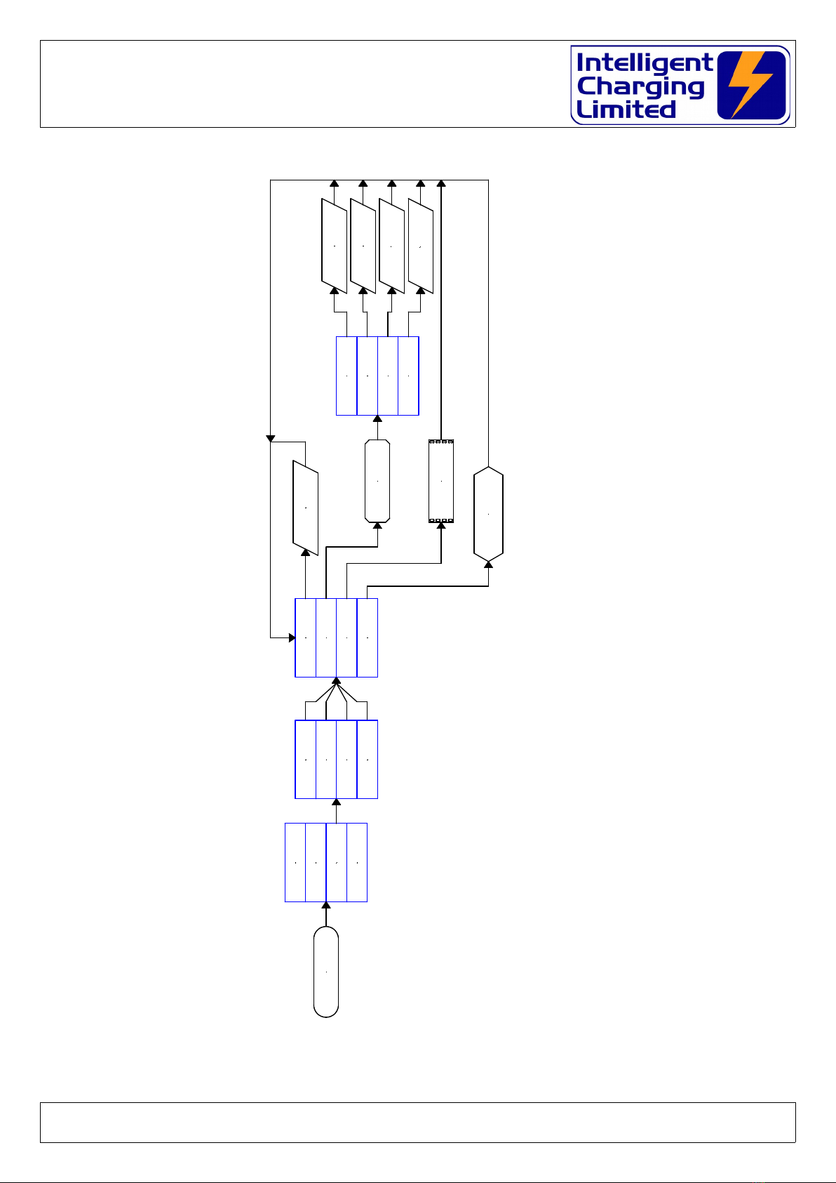
3. Capacity Testing Menu
Doc: DWG1062-06-R3 IC8P Operators manual.odt Pa e 11 of 46 Copyright Material of Intelligent Charging Limited © 2018
Printed On : 20/11/19
MAIN MENU
CHARGE
DISCHARGE
PROCESS
SETTINGS
LIBRARY
MANUAL
PREVIOUS
GET
LIBRARY START
TIMED
GET
MANUAL
GET
PREVIOUS
EXECUTE
CAPTEST
REQUEST
TIME
DISPLAY
CAPTEST DATA
WAIT
DELAY

IC8P Battery Charger/Analyser
Operator Manual
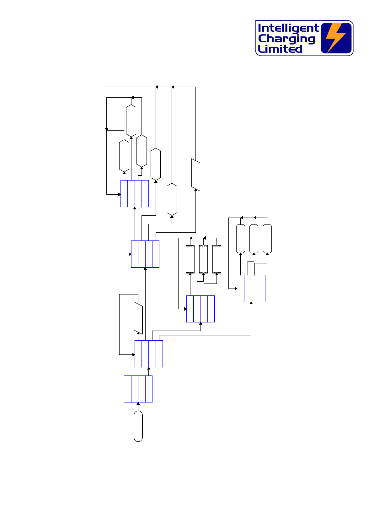
3.3 Process Operation Menu
Doc: DWG1062-06-R3 IC8P Operators manual.odt Pa e 12 of 46 Copyright Material of Intelligent Charging Limited © 2018
Printed On : 20/11/19
IC8P Battery Charger/Analyser
Operator Manual
Doc: DWG1062-06-R3 IC8P Operators manual.odt Pa e 13 of 46 Copyright Material of Intelligent Charging Limited © 2018
Printed On : 20/11/19
MAIN MENU
CHARGE
DISCHARGE
PROCESS
SETTINGS
PROCESS #1
PROCESS #2
PROCESS #3
PROCESS #4
RENAME
VIEW/EDIT
PRINT
EXECUTE
REQUEST
NAME
NEXT STEP
PREV STEP
CLR STEP
MODIFY
DISPLAY
PROCESS DATA
PRINT
PROCESS DATA
SELECT
NEXT STEP
SELECT
PREV STEP
REMOVE
STEP
REQUEST
DATA
EXECUTE
PROCESS
IC8P Battery Charger/Analyser
Operator Manual
3.4 Settings Menu
Doc: DWG1062-06-R3 IC8P Operators manual.odt Pa e 14 of 46 Copyright Material of Intelligent Charging Limited © 2018
Printed On : 20/11/19
ADJUSTMENT
MAIN MENU SET CLOCK
SYSTEM
PRINT
DISPLAY
GET CLOCK
DATA
CALIBRATE
CONTROL
RESET
RESET DATE CALIBRATION
DATE SET CALIBRATION
ADJUST
CONTROL
FUNCTION
PARAMETERS
RESET
BATT S/N
BATT S/N
YES/NO
CHARGE
DISCHARGE
PROCESS
SETTINGS
PREVIOUS
SYSTEM
BATTERY
PRINT
PREVIOUS DATA
PRINT
SYSTEM DATA
PRINT
BATTERY DATA
PREVIOUS
SYSTEM
BATTERY
DISPLAY
PREVIOUS DATA
DISPLAY
SYSTEM DATA
DISPLAY
BATTERY DATA
GET LEAD
VOLT DROP
LEADS

IC8P Battery Charger/Analyser
Operator Manual
4 Connecting A Battery
For all metho s of use of the battery charger the battery to be teste or charge must only be
connecte when the charger is either:
Not powere up,
or
Powere up an not executing a charge or capacity test function. Doing so woul amage the
equipment, an possible raw an electrical arc that, may cause an explosion from the venting
gases being emitte from the battery.
Care must also be execute in ensuring that the bare en s of the battery lea s o not come
in contact with the metalwork of the charger as this may also cause electrical arcing an or
explosion risk.
THE BATTERY SHOULD NEVER BE CONNECTED OR DISCONNECTED FROM THE UNIT
WHEN A CHARGE OR TEST IS IN PROGRESS AS ARCING CAN OCCUR CAUSING AN
EXPLOSION FROM GASSES VENTING FROM BATTERIES BEING PROCESSED
THE BATTERY SHOULD ALWAYS BE ISOLATED FROM ANY EQUIPMENT BEFORE
BEING CONNECTED
Stray groun loops between the attache equipment an the Battery Charger Analyser coul
cause catastrophic amage to the unit an the attache equipment.
Provi e with the unit is one set of lea s terminate with 8mm Ring Crimp Connectors. The
8mm ring crimps shoul be fitte with suitable battery connectors to suit the battery being
charge .
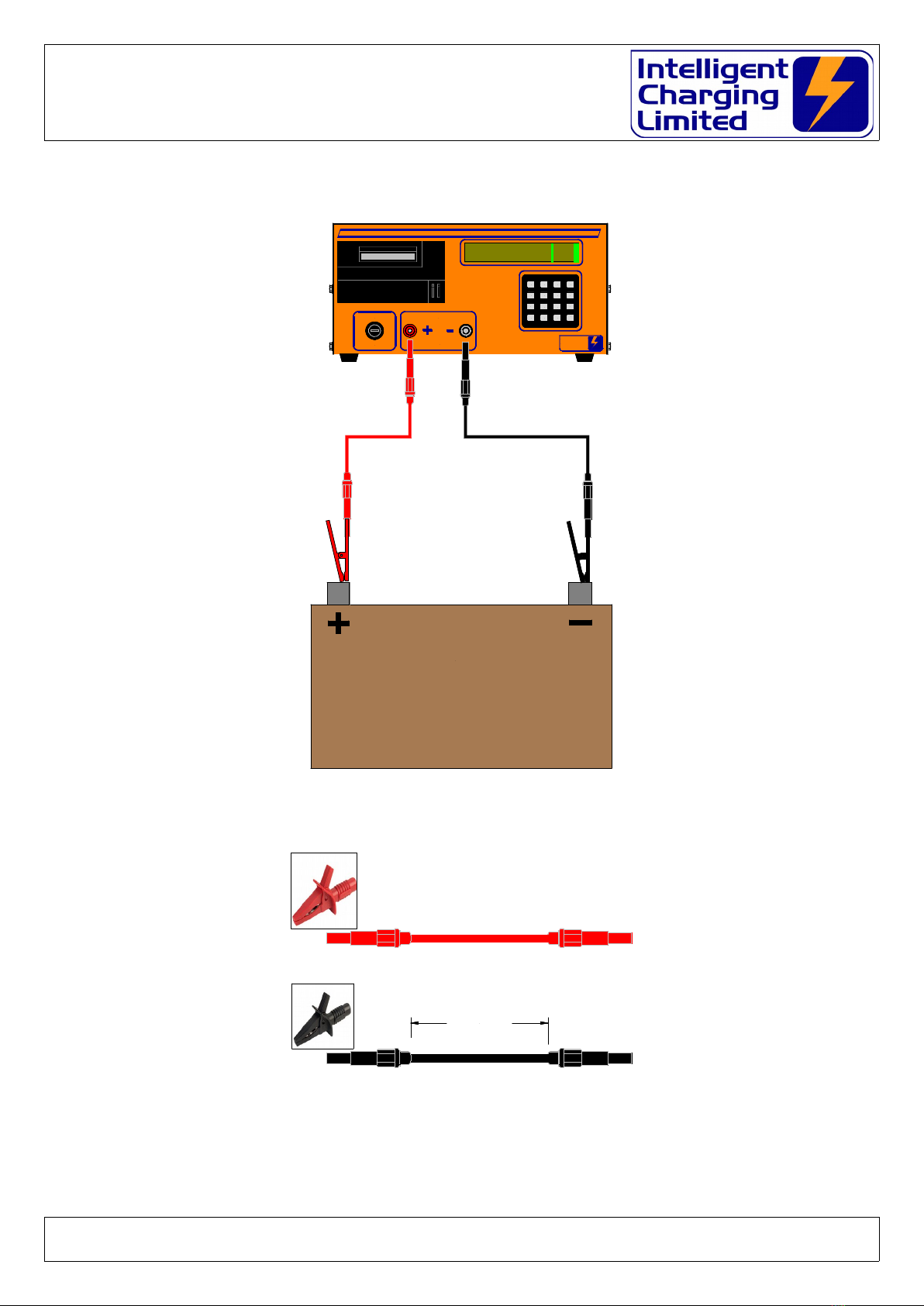
Always connect the battery lea s as shown in the following figure to the unit before
attempting to connect the battery to be charge /teste . Once the charger lea s are connecte
to the unit then the battery can be connecte .
Doc: DWG1062-06-R3 IC8P Operators manual.odt Pa e 15 of 46 Copyright Material of Intelligent Charging Limited © 2018
Printed On : 20/11/19
IC8P Battery Charger/Analyser
Operator Manual
BATTERY LEAD CONNECTION
STANDARD LEAD SET
Specialist lea sets are available by request to suit many battery types.
Please contact Intelligent Charging Limite for prices an availability.
Doc: DWG1062-06-R3 IC8P Operators manual.odt Pa e 16 of 46 Copyright Material of Intelligent Charging Limited © 2018
Printed On : 20/11/19
Intelligent
Charging
Limited
1
7
4
CLR
2
5
0
8
3
6
9
ENT
A
B
C
.
16A QB
IC8P
** SERVICEABLE **
24 Jun 2015 14:01 o
CHARGE
CAPTEST
SETTINGS
LIBRARY
A
C
B
.
Bat 12.0V
INTELLIGENT CHARGING LIMITED
BATTERY CHARGER & CAPACITY TESTER IC8P
BATTERY MUST BE ISOLATED FROM
EQUIPMENT BEFORE CONNECTION
BATTERY
BATTERY FUSE
AVIATION BATTERY
Cable Cut 50cm
IC8P Battery Charger/Analyser
Operator Manual
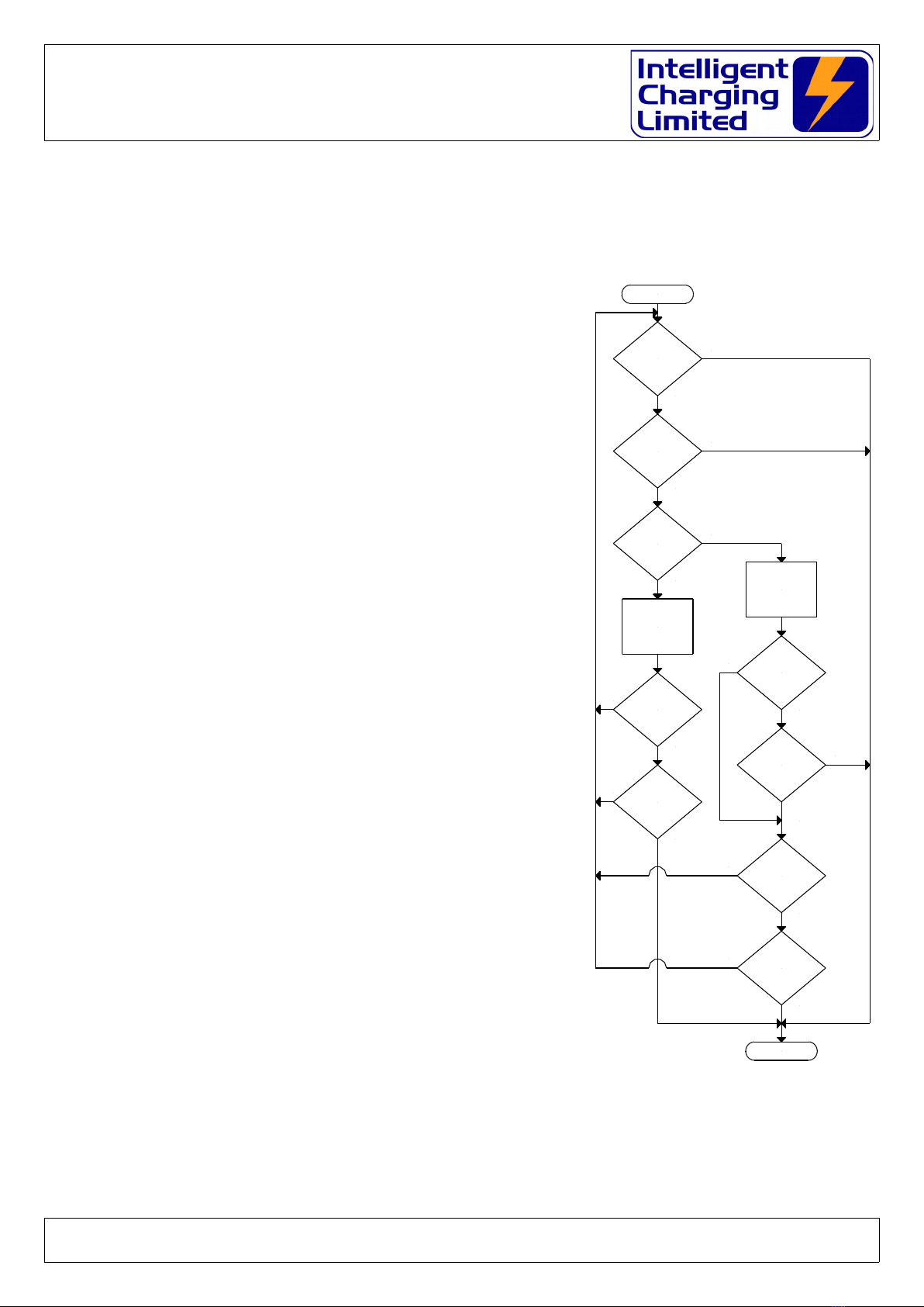
5 Battery Charge Operation
5.1 Constant Voltage Charge
This charge mo e is esigne primarily for Lea
Aci batteries, but can be use for any type of
battery, which requires top-up charging through a
constant potential of the battery voltage. The
battery will be charge at the amount of amps
specifie until the target voltage has been achieve .
At this point the charging amps will gra ually re uce
to zero as the battery voltage is maintaine . This
will continue until the charge time has been
complete . The parameters for the charge are as
follows: -
Target Volts : This is the constant potential
voltage of the battery.
Charge Amps : This is the maximum amount of
amps to eliver to the battery. Once the Target
Volts has been reache the amount of amps
elivere to the battery will ecrease.
Charge Time : This is the maximum charge
uration.
Minimum Amps : When the amount of amps
elivere to the battery falls below this value the
charge will stop. Set to zero if not require .
Amps Rise : If the current shoul increase to
above this setting once the Target Volts has been
reache the charge will stop. Set to zero if not
require .
Target Fail Time : If the Target Volts has not
been reache within this value of time then the
charge will stop. Set to zero if not require .
Doc: DWG1062-06-R3 IC8P Operators manual.odt Pa e 17 of 46 Copyright Material of Intelligent Charging Limited © 2018
Printed On : 20/11/19
MAINTAIN
CHARGE
CURRENT
START
TIME
TO TARGET
ELAPSED
?
TARGET
VOLTAGE
REACHED
?
NO
YES
YES
NO
CHARGE
TIME ELAPSED
?
CONTROL
AMPS TO
MAINTAIN
TARGET VOLTS
CLR KEY
PRESSED
?
TIME
TO TARGET
GT ZERO
?
NO
YES
NO
YES
NO
YES
CHARGE
AMPS LT
MIN AMPS
?
MIN AMPS
GT ZERO
?
AMPS
RISE
ABOVE
THRESHOLD
?
AMPS RISE
GT ZERO
?
STOP CHARGE
YES
NO
YES
NO
YES
NO
YES
NO
IC8P Battery Charger/Analyser
Operator Manual
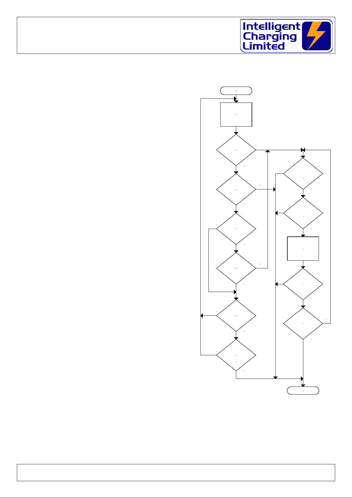
5. Constant Current Charge
This charge mo e is esigne primarily for
NiC type batteries, but can be use for
any battery type, which requires a constant
current charge. The charge current is
maintaine at a constant current until the
target voltage has been reache . The
parameters for the charge are as follows: -
Target Volts : This is the voltage at
which point the charge will stop, or switch
to Extra Time.
Charge Amps : This is the constant
current amps to eliver to the battery up
until the Target Volts has been reache .
Maximum Time: This is the maximum
time that the main charge can be applie , if
zero is entere the extra target fail time will
be requeste .
Target Fail : If the Target Volts has not
been reache within this value of time then
the charge will stop. Set to zero if not
require .
Extra Time : If set to a value greater
than zero the charge will continue for this
Extra Time once the Target Voltage has
been achieve .
Extra Amps : If the Extra Time has
been set to a value greater than zero this
efines the constant current amps to
eliver to the battery uring the Extra
Time.
Overcharge Volts : During the Extra Time the charge will stop if the battery
voltage reaches this value.
Doc: DWG1062-06-R3 IC8P Operators manual.odt Pa e 18 of 46 Copyright Material of Intelligent Charging Limited © 2018
Printed On : 20/11/19
MAINTAIN
CHARGE
CURRENT
START
TARGET
MAX TIME
ELAPSED
?
TARGET
VOLTAGE
REACHED
?
NO
YES
NO
MAINTAIN
ADDITIONAL
CHARGE
CURRENT
CLR KEY
PRESSED
?
TARGET
MAX TIME
GT ZERO
?
YES
NO
YES
NO
YES
ADDITIONAL
TIME
ELAPSED
?
ADDITIONAL
TIME SET
?
BATTERY
VOLTS ABOVE
OVERCHARGE
?
STOP CHARGE
YES
NO
YES
NO
YES
NO
YES
CLR KEY
PRESSED
?
NO
TARGET
FAIL TIME
ELAPSED
?
TARGET
FAIL TIME
GT ZERO
?
NO
NO
YES
YES

IC8P Battery Charger/Analyser
Operator Manual
5.3 Multi-Step Constant Current Charge
This charge mo e is esigne for NiC batteries but can be
use for any type of battery, which requires multi-step
constant current charge. The unit will charge at the set amps
for the time set for each step. During the charge the battery
voltage will be monitore an the charge will stop if the
overcharge voltage is excee e . During the charge pressing
the ‘ENT’ key can manually a vance each step. The
parameters for the charge are as follows: -
Step #1 Charge Amps : This is the constant current
amps for step 1.
Step #1 Charge Time : This is the amount of time the
charge is maintaine for step 1.
Step # Charge Amps : This is the constant current
amps for step 2.
Step # Charge Time : This is the amount of time the
charge is maintaine for step 2.
Step #3 Charge Amps : This is the constant current
amps for step 3.
Step #3 Charge Time : This is the amount of time the
charge is maintaine for step 3.
Step #4 Charge Amps : This is the constant current
amps for step 4.
Step #4 Charge Time : This is the amount of time the
charge is maintaine for step 4.
Overcharge Volts : During the charge if the battery
voltage excee s this value then the charge will stop.
Note : Steps can have zero Charge Amps if a pause in
charging is require between steps.
Steps that are not nee e are simply set to zero Charge
Time an zero Charge Amps.
At any time uring the charge a step can be a vance before
the time has elapse by pressing the ‘ENT’ key.
Doc: DWG1062-06-R3 IC8P Operators manual.odt Pa e 19 of 46 Copyright Material of Intelligent Charging Limited © 2018
Printed On : 20/11/19
MAINTAIN
STEP CHARGE
CURRENT
START
STEP
CHARGE TIME
ELAPSED
?
YES
NO
CHANGE TO
NEXT STEP
CLR KEY
PRESSED
?
YES
NO
YES
MORE
STEPS
?
BATTERY
VOLTS ABOVE
OVERCHARGE
?
STOP CHARGE
NO
YES
NO
ENT KEY
PRESSED
?
NO
YES

IC8P Battery Charger/Analyser
Operator Manual
5.3.1 CHARGE FROM A LIBRARY ENTRY
•Connect the battery to be charge an apply power to the unit.
•From the MAIN screen select CHARGE followe by LIBRARY.
•Using the arrows move the high light to point to the battery.
•Select EXECUTE.
•If a blank entry is selecte the unit will warn that no ata is exists.
•The unit will isplay the charge ata for checking.
•To begin the charge select START or TIMED.
•If printer fitte an battery serial number set to on, the battery serial number
will be requeste at this point.
5.3. CHARGE FROM MANUAL DATA
•Connect the battery to be charge an apply power to the unit.
•From the MAIN screen select CHARGE followe by MANUAL.
•Enter the charge ata as requeste .
•The unit will isplay the charge ata for checking.
•To begin the charge select START or TIMED.
•If printer fitte an battery serial number set to on, the battery serial number
will be requeste at this point.
5.3.3 CHARGE FROM PREVIOUS DATA
•Connect the battery to be charge an apply power to the unit.
•From the MAIN screen select CHARGE followe by PREVIOUS.
•The unit will isplay the charge ata for checking.
•To begin the charge select START or TIMED.
•If printer fitte an battery serial number set to on, the battery serial number
will be requeste at this point.
Doc: DWG1062-06-R3 IC8P Operators manual.odt Pa e 20 of 46 Copyright Material of Intelligent Charging Limited © 2018
Printed On : 20/11/19
Table of contents
Other Intelligent Charging Batteries Charger manuals


