manuals.online logo
Brands
  1. Home
  2. •
  3. Brands
  4. •
  5. CTEK
  6. •
  7. Batteries Charger
  8. •
  9. CTEK D250SE User manual

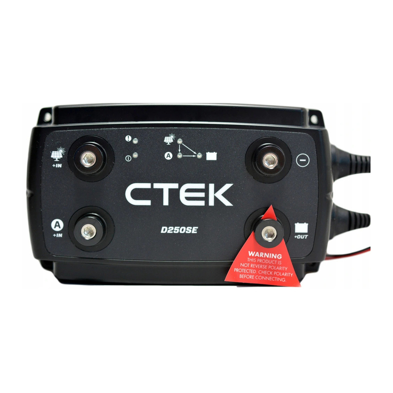
CTEK D250SE User manual

Date: 2020-10-01
Version: 1.0 Title: D250SE & SMARTPASS 120S
* Fuse recomended. Please verify directive for applicable installation regarding fuses
Alternator
Starter motor
Fuse*
Temperaturesensor
Temperature sensor
RED = Smart Alternator cable
BLACK = Battery selector
Smart alternator cable (red)
• Notconnected = Conventional alternator
• Connected to ignition = Smart alternator
Battery selector cable (black)
• Notconnected = 14.4V charge voltage
• Connected to minus= 14.7V charge voltage
• Connected to +12V = LiFePO4
Fuse*
Date: 2020-10-01
Version: 1.0 Title: D250SE & SMARTPASS 120S
Starter battery:
A start battery should never be deeply discharged and should
be capable of delivering high current for a short period of
time.
The starter battery should be a Lead Acid battery designed for
automotive applications. This does not affect the chemistry
chosen for the Service battery
Service battery:
Also known as secondary battery, it should be of the type
deep cycle batteries. The size should be 20Ah to 300Ah or
even up to 800Ah with SMARTPASS 120S installed.
You can install several batteries in parallel in order to increase
the total capacity (Ah) of your service battery bank.
If possible, the service battery should be installed in a well-
ventilated space away from the engine bay, unless the battery
is designed for it.
Install the service battery as close as possible to the charger,
preferably not further away than 2m, which is the length of
temperature sensor cable.
D250SE:
The D250SE is a DCDC charger, i.e. it is a dual input battery
charger with an alternator or a solar panel as its power
source. Please note that the alternator needs to be directly
connected to a starter battery and that the D250SE is design
to separate a starter and service battery
The charger will work in parallel with both SMARTPASS 120S
as well as another D250SE.
The maintenance charge of your starter battery, that is
facilitated with the help from a solar panel, is a small pulse
charge (3sec with a 15 sec interval) that will compensate for
the self discharge of your starter battery. Note, this should
not be mistaken for a normal charge of the battery.
Install according to manual.
Temperature sensor:
For D250SE and SMARTPASS 120S the temperature sensor
ensures that the battery is only charged within its
temperature range and helps detect a damaged battery that is
overheating. In the latter case the charger will stop charging
the battery and indicate fault. D250SE also uses the
temperature senor to enable temperature regulation of the
charge voltage
Fuses:
We recommend that all cables directly attached to a battery
holds a fuse as close as possible to the battery in order to
protect the cable.
See manual for fuse size.
Charge voltage:
You can choose between 14.4V (WET) /14.7V (AGM) / 14,2V
(LiFePO4) on D250SE as the nominal charging voltage. This is
done by connecting the black battery select cable to +12V for
LiFePO4 mode or earth for AGM mode or not connected at all
for WET mode.
Please note that the charge voltage levels are applied to the
absorption phase (constant voltage phase), during bulk
(constant current) the charge voltage will be lower but slowly
increasing with the state of charge of the battery. See manual
and Charge program charts for more information.
WET and AGM mode have a temperature regulated charge
voltage, where the nominal voltage is reached at 25 degrees
Celsius. Below that it is increased by 23mV per degree Celsius
and vice versa if the temperature is higher.
SMARTPASS 120S:
Is a smart combination of relays (actually MOSFETS) that
connects starter and service batteries. This enables current
from your alternator to charge both batteries.
The SMARTPASS 120S will not control the voltage applied to
the service battery. For that you need a D250SE installed in
parallel.
The current through the SMARTPASS 120S to a service battery
depends on the alternator output voltage, cable length/
dimension and the charge acceptance of your battery. The
max continuous current is 120A.
Start assistance.
SMARTPASS 120S automatically connects the service and
starter battery, if the starter battery on its own is unable to
start the engine. After the start assistance function
has been activated, SMARTPASS 120S will display a fault
indication that remains until starting has been achieved
without the use of the start assistance function.
Install according to instruction manual.
Date: 2020-10-01
Version: 1.0 Title: D250SE & SMARTPASS 120S
Cables:
For the best possible functionality follow the instructions in
the manual regarding cable dimensions and make sure the
cables are as short as possible in order to minimize voltage
drops.
All cables should be firmly mounted and preferably in a cable
protection tube minimizing wear and tear from the vibrations
in your vehicle.
Busbars can be used to make the installation neat and tidy
and the use of tubular ring terminals (size M8) properly
crimped will reduce unnecessary resistance in the
connections.
Note, the weaker cable recommendation to the negative
terminal (D250SE) is chosen since it only carries current to the
control electronics, not the charge current. The latter will flow
through earth, which is connected to the negative terminal of
your battery
Alternator:
The Alternator is the power source for both D250SE and
SMARTPASS 120S, i.e. should be able to power the application
where these units are installed.
Smart alternators was introduced in the Euro 5 & 6 engines,
where they help the engine reduce its emissions by enabling
brake regeneration. If you have a Smart alternator connect
the red Smart Alternator signal cable to a +12V source that is
live when the engine is running (for example contact no. 15
Ignition in the DIN 72552 standard) in order to get proper
functionality from the D250SE / SMARTPASS 120S. Please
note, that connecting this wire to a source that is live
continuously will make the units active continuously as well,
possibly rendering a starter battery with low state of charge.
If the Alternator has a sense wire connected to the Service
battery make sure it is moved to the Starter battery when
installing the D250SE/SMARTPASS120S. Note, a sense wire is
typically found in Volvo Penta marine applications.
Consumers:
Consumers (max 80A continuously) should be connected to
the consumer output terminal of the SMARTPASS 120S. If the
service battery voltage becomes critically low, the consumer
output terminal is deactivated in order to protect the service
battery, i.e. under voltage protection.
Consumers that should not be affected by this under voltage
protection should be connected directly to your service
battery, typically high priority consumers like VHF radio.
Consumers connected to the consumer output receives
current from the alternator instead of the service battery
during driving. This makes the charging of the service battery
faster and if the battery is fully charged it is put in a rest state,
which increases the lifetime of the service battery.

Other manuals for D250SE

1

This manual suits for next models

1

Other CTEK Batteries Charger manuals

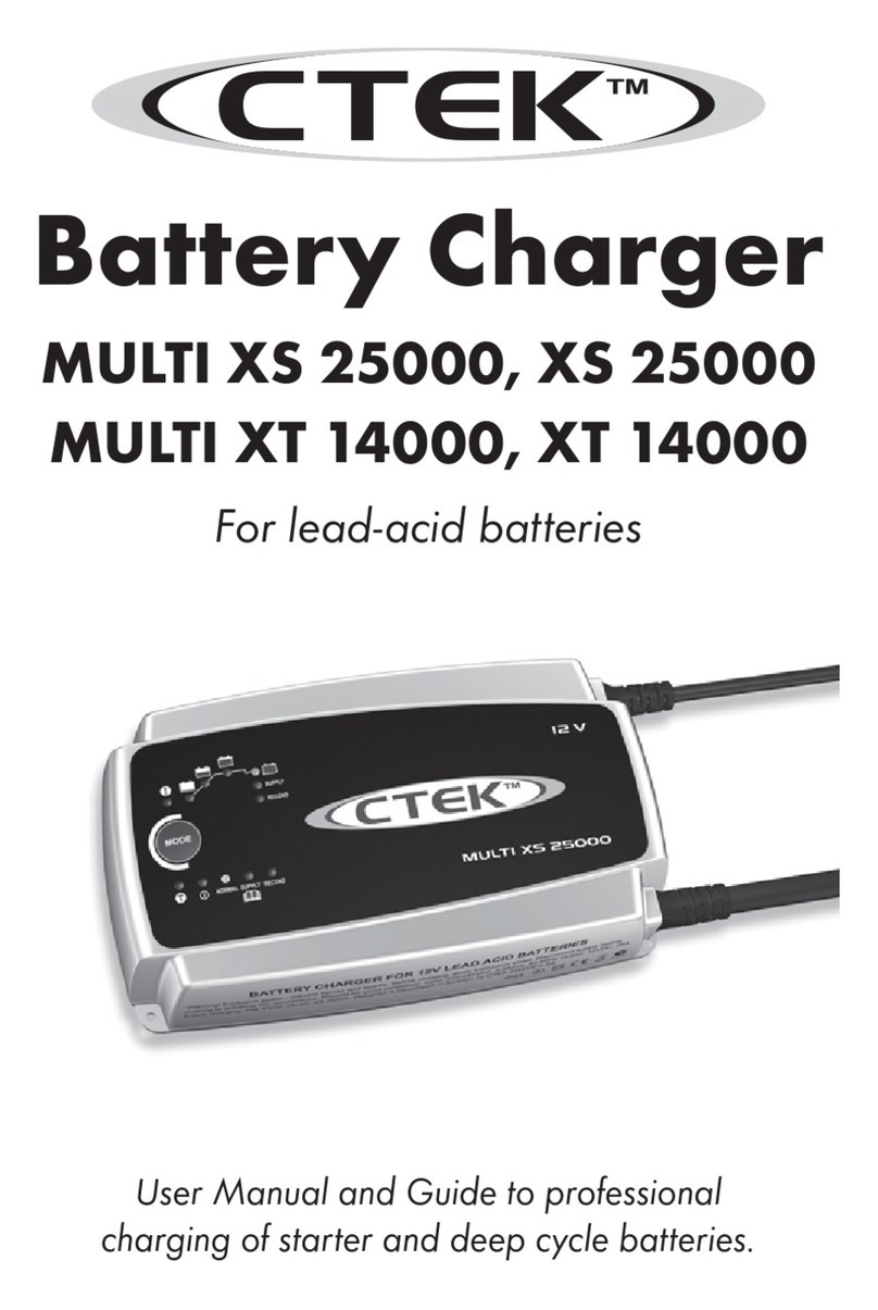
CTEK MULTI XS 25000 User manual

CTEK

CTEK MULTI XS 25000 User manual

CTEK MUS 4.3 User manual

CTEK

CTEK MUS 4.3 User manual

CTEK MXS 10 User manual

CTEK

CTEK MXS 10 User manual

CTEK MXS 3.6 User manual

CTEK

CTEK MXS 3.6 User manual

CTEK XS 800 User manual

CTEK

CTEK XS 800 User manual

CTEK XS 800 User manual

CTEK

CTEK XS 800 User manual

CTEK 1055 User manual

CTEK

CTEK 1055 User manual

CTEK MXS 10 User manual

CTEK

CTEK MXS 10 User manual

CTEK D250S Dual User manual

CTEK

CTEK D250S Dual User manual

CTEK MULTI US 7000 User manual

CTEK

CTEK MULTI US 7000 User manual

CTEK UC 800 1019 Assembly instructions

CTEK

CTEK UC 800 1019 Assembly instructions

CTEK 1064 User manual

CTEK

CTEK 1064 User manual

CTEK MUS 4.3 POLAR User manual

CTEK

CTEK MUS 4.3 POLAR User manual

CTEK battery charger User manual

CTEK

CTEK battery charger User manual

CTEK 1018 User manual

CTEK

CTEK 1018 User manual

CTEK MXT 14000 AE User manual

CTEK

CTEK MXT 14000 AE User manual

CTEK MXS 5.0 User manual

CTEK

CTEK MXS 5.0 User manual

CTEK POWERSPORT User manual

CTEK

CTEK POWERSPORT User manual

CTEK PRO120 User manual

CTEK

CTEK PRO120 User manual

CTEK MXS 10 User manual

CTEK

CTEK MXS 10 User manual

CTEK MXS 10 User manual

CTEK

CTEK MXS 10 User manual

CTEK D250SA User manual

CTEK

CTEK D250SA User manual

CTEK MXS 5.0 CHECK User manual

CTEK

CTEK MXS 5.0 CHECK User manual

CTEK MXS 25 User manual

CTEK

CTEK MXS 25 User manual

Popular Batteries Charger manuals by other brands

Projecta HDBC90 user manual

Projecta

Projecta HDBC90 user manual

Carel EVBAT00400 manual

Carel

Carel EVBAT00400 manual

Colentris Battery TRAINER Original operating instructions

Colentris

Colentris Battery TRAINER Original operating instructions

MAXOAK AC012K-HU-35 manual

MAXOAK

MAXOAK AC012K-HU-35 manual

GYS GYSFLASH 6.24 manual

GYS

GYS GYSFLASH 6.24 manual

CLAS OE 8004 manual

CLAS

CLAS OE 8004 manual

SolaX Power X1-EVC Series Quick installation guide

SolaX Power

SolaX Power X1-EVC Series Quick installation guide

Olympus ET-CK30 instruction manual

Olympus

Olympus ET-CK30 instruction manual

NOCO Genius G7200EU User guide & warranty

NOCO Genius

NOCO Genius G7200EU User guide & warranty

Entel CSBHX(V2) operating instructions

Entel

Entel CSBHX(V2) operating instructions

Goobay 59357 manual

Goobay

Goobay 59357 manual

Parkside PAP 20 B1 Translation of the original instructions

Parkside

Parkside PAP 20 B1 Translation of the original instructions

Associated Equipment 9640 Operator's manual

Associated Equipment

Associated Equipment 9640 Operator's manual

UNI POWERFIX 10204 operating instructions

UNI

UNI POWERFIX 10204 operating instructions

DEFA ShowroomCharger 32A user guide

DEFA

DEFA ShowroomCharger 32A user guide

AddEnergie FLO SmartDC installation guide

AddEnergie

AddEnergie FLO SmartDC installation guide

ANSMANN ALCT 6-24/1 operating instructions

ANSMANN

ANSMANN ALCT 6-24/1 operating instructions

Belkin F8Z498cw user manual

Belkin

Belkin F8Z498cw user manual

manuals.online logo
manuals.online logoBrands
  • About & Mission
  • Contact us
  • Privacy Policy
  • Terms and Conditions

Copyright 2025 Manuals.Online. All Rights Reserved.