Intelligent Charging SBSC11Q User manual

SBSC11Q Four channel SLA Battery Charger
Operator Manual
Doc: DWG1057-09-R2 SBSC11Q Operators manual.o t Page 1 of 18 Copyright Material of Intelligent Charging Limited © 2018
Printed On : 17/07/19
SBSC11Q
BATTERY CHARGER
OPERATORS MANUAL

SBSC11Q Four channel SLA Battery Charger
Operator Manual
Table of Contents
1 Manual Revision History............................................................................................................3
2 General Information..................................................................................................................4
3 Controls and Indicators.............................................................................................................5
4 Connecting A attery................................................................................................................7
4.1 attery Lead Connection.....................................................................................................8
5 Operating The Unit...................................................................................................................9
6 Display rightness...................................................................................................................10
7 Performing calibration.............................................................................................................11
7.1 Equipment Required.........................................................................................................11
7.2 Calibration Equipment Connection.....................................................................................11
7.3 Check Procedure..............................................................................................................11
7.4 Calibration Adjustment.....................................................................................................12
7.4.1 Voltage Adjustment...................................................................................................12
7.4.2 Current Adjustment...................................................................................................13
8 Error Conditions......................................................................................................................14
9 Specifications..........................................................................................................................15
10 General Arrangement............................................................................................................16
11 Product Warranty..................................................................................................................17
Doc: DWG1057-09-R2 SBSC11Q Operators manual.o t Page 2 of 18 Copyright Material of Intelligent Charging Limited © 2018
Printed On : 17/07/19

SBSC11Q Four channel SLA Battery Charger
Operator Manual
1 Manual Revision istory
Rev Date Description
0 22-08-2011 First write.
1 12-09-2011 Proof rea .
2 21-07-2015 Formatting changes.
Doc: DWG1057-09-R2 SBSC11Q Operators manual.o t Page 3 of 18 Copyright Material of Intelligent Charging Limited © 2018
Printed On : 17/07/19
SBSC11Q Four channel SLA Battery Charger
Operator Manual
2 General Information
The S SC11Q is a battery charger designed to simultaneously charge up to four
S SC11 sealed lead acid batteries or other S S type batteries having a nominal
voltage of 12.0V.
It is housed in a metal enclosure designed for bench mounting.
attery charge control is simply via STOP/START push buttons, allowing battery
interchange without the need to remove power from the unit or
connecting/disconnecting live output.
The battery connecting lead is made via a non reversible 2 pin 50A connector.
The unit is supplied with two lead sets per channel one set will be fitted with two
crocodile or alligator clamps the second set will be fitted with 8.0mm crimp
terminals for connection to the S SC11 battery.
The unit is reverse connection protected and will show an error condition if START
is pressed while battery reverse connection is made.
The unit detects non battery connection and will show an error if less than 0.8V is
detected at the battery terminals.
The unit will automatically perform a desulphation charge if a battery connected
exhibits a terminal voltage less than 9.0V
Field calibration possible, no need to return the unit back to factory for calibration.
10.0A Resettable circuit breakers are fitted to each battery connection to protect
both the battery and the unit from short circuits or faults.
The unit accepts a universal mains input of 80-264 VAC/47-63 Hz.
attery volts / amps and time is displayed on a three digit red 7 segment display.
Display and Indicators brightness can be controlled from dim to very bright so
display can be seen in daylight conditions.
Clear indication of ulk Charge, Trickle Charge, Desulphation Charge and Error
conditions.
Doc: DWG1057-09-R2 SBSC11Q Operators manual.o t Page 4 of 18 Copyright Material of Intelligent Charging Limited © 2018
Printed On : 17/07/19
SBSC11Q Four channel SLA Battery Charger
Operator Manual
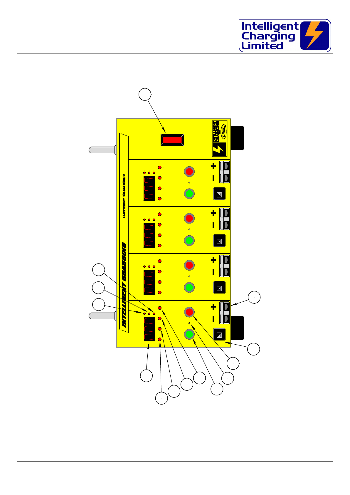
3 Controls and Indicators
(1) Mains Power Switch. Operating this switch applies mains power to the unit. This switch
is also a circuit breaker rated at 7.0A.
Doc: DWG1057-09-R2 SBSC11Q Operators manual.o t Page 5 of 18 Copyright Material of Intelligent Charging Limited © 2018
Printed On : 17/07/19
10A
ERR
SBSC11Q
POWER
START STOP
OUTPUT #1
RUN DSUL
10A
10A
10A
Press To Reset Press To Reset Press To Reset Press To Reset
VOLTS
AMPS
TIME
TRIC ERR
START STOP
OUTPUT #2
RUN DSUL
VOLTS
AMPS
TIME
TRIC ERR
START STOP
OUTPUT #3
RUN DSUL
VOLTS
AMPS
TIME
TRIC ERR
START STOP
OUTPUT #4
RUN DSUL
VOLTS
AMPS
TIME
TRIC
1
2
3
4
5
6
7
8
9
10
11
12 13 14

SBSC11Q Four channel SLA Battery Charger
Operator Manual
(2) Output attery Connector. This is where the battery lead is connected.
(3) Circuit reaker. This is a resettable thermal 10.0A circuit breaker designed to protect
the equipment in event of overload.
(4) STOP Push button. This button has to be pressed to stop a battery charge.
(5) FUNCTION access. A hidden button behind this hole is used to gain access to the
internal functions like calibration.
(6) START Push utton. Pressing this with a correct battery connected starts the charge
process. While the RUN lamp is illuminated repeated pressing of the start button will
change the display to show Volts, Amps and Time.
(7) ERROR Indicator. This indicator will indicate if the charge detects a problem with the
battery or charge. When illuminated the display will show the error number.
(8) DSUL Indicator. This indicator will illuminate if the charger is working in desulphation
mode.
(9) TRICKLE Indicator. This indicator will illuminate when the charger is in trickle charge
mode.
(10) RUN Indicator. This indicator will illuminate when the charger is operating, if the other
three indicators are extinguished then the charger is operating in bulk charge mode.
(11) Seven Segment Display. This is the three digit display which will display battery voltage,
charge current, and elapsed time.
(12) Volts Indicator. This indicator will be illuminated if the display is showing battery volts.
(13) Amps Indicator. This indicator will be illuminated if the display is showing charge amps.
(14) Time Indicator. This indicator will be illuminated if the display is showing the elapsed
charge time.
Doc: DWG1057-09-R2 SBSC11Q Operators manual.o t Page 6 of 18 Copyright Material of Intelligent Charging Limited © 2018
Printed On : 17/07/19

SBSC11Q Four channel SLA Battery Charger
Operator Manual
4 Connecting A Battery
For all methods of use of the battery charger the battery to be charged must only be
connected when the charger is either:
Not powered up,
or
Powered up and not executing a charge function. Doing so would damage the equipment, and
possible draw an electrical arc that, may cause an explosion from the venting gases being
emitted from the battery.
Care must also be executed in ensuring that the bared ends of the battery leads do not come
in contact with the metalwork of the charger as this may also cause electrical arcing and or
explosion risk.
T E BATTERY S OULD NEVER BE CONNECTED OR DISCONNECTED FROM T E UNIT
W EN A C ARGE IS IN PROGRESS AS ARCING CAN OCCUR CAUSING AN
EXPLOSION FROM GASSES VENTING FROM BATTERIES BEING PROCESSED
T E BATTERY S OULD ALWAYS BE ISOLATED FROM ANY EQUIPMENT BEFORE
BEING CONNECTED
Stray ground loops between the attached equipment and the attery Charger could cause
catastrophic damage to the unit and the attached equipment.
Provided with the unit is two sets of leads. One set terminated with 8mm Ring Crimp
Connectors designed to mate directly to batteries fitted with 8.0mm threaded posts. The other
set is fitted with crocodile or alligator clamps designed for batteries which are not fitted with
8.0mm threaded posts.
Always connect the battery leads as shown in the following figure to the battery first before
attempting to connect the charging lead to the battery charger.
Doc: DWG1057-09-R2 SBSC11Q Operators manual.o t Page 7 of 18 Copyright Material of Intelligent Charging Limited © 2018
Printed On : 17/07/19

SBSC11Q Four channel SLA Battery Charger
Operator Manual
4.1 Battery Lead Connection
When charging has competed the battery plug must be removed from the charger
before being removed from the battery.
Specialist lead sets are available by request to suit many battery types.
Please contact Intelligent Charging Limited for prices and availability.
Doc: DWG1057-09-R2 SBSC11Q Operators manual.o t Page 8 of 18 Copyright Material of Intelligent Charging Limited © 2018
Printed On : 17/07/19
SBSC11 BATTERYSBSC11 BATTERYSBSC11 BATTERY
SBSC11 BATTERY
10A
ERR
SBSC11Q
POWER
START STOP
OUTPUT #1
RUN DSUL
10A
10A
10A
Press To Reset Press To Reset Press To Reset Press To Reset
VOLTS
AMPS
TIME
TRIC ERR
START STOP
OUTPUT #2
RUN DSUL
VOLTS
AMPS
TIME
TRIC ERR
START STOP
OUTPUT #3
RUN DSUL
VOLTS
AMPS
TIME
TRIC ERR
START STOP
OUTPUT #4
RUN DSUL
VOLTS
AMPS
TIME
TRIC

SBSC11Q Four channel SLA Battery Charger
Operator Manual
5 Operating The Unit
The battery to be charged must be connected to the unit in the correct manner and
must not under any circumstanced still be connected to any other equipment.
Connect the RED battery lead to the +ve battery terminal and the LACK battery
lead to the -ve battery terminal.
Insert the two pole battery lead connector into the mating socket on the battery
charger on any unused channel.
If the battery charger is not powered on, apply mains power by operating the power
switch.
On the channel that has been connected press START.
If the battery terminal voltage is above 9.0V the battery charger will perform a bulk
charge of 9.0A until the battery terminal voltage reaches 14.4V. During bulk charge
the RUN indicator will be on continuously. Once the set point has been reached the
charger will switch to trickle charge whereby it will maintain battery terminal voltage
of 13.74V. During the trickle charge stage the TRICKLE indicator will be on
continuously.
If the battery terminal voltage is below 9.0V the charger will automatically go into
desulphation charge mode. It will float charge the battery at 13.74V until the charge
current stabilises at 20mA, whereby the charge will then switch into normal RUN
mode. Note this process may take several days. While the desulphation mode is
active the DESUPLHATION indicator will be on continuously.
If the START button is pressed and the battery terminal voltage is less than 0.8V the
RED indicator will illuminate and the display will show “E01”.
At the end of the charge cycle or at any point during a charge cycle the STOP
button can be pressed to terminate charge mode.
If an error occurs during the charge cycle the charge will automatically stop and the
ERROR indicator will be illuminated and the display will show an error code. To clear
the error display the STOP button must be pressed.
Doc: DWG1057-09-R2 SBSC11Q Operators manual.o t Page 9 of 18 Copyright Material of Intelligent Charging Limited © 2018
Printed On : 17/07/19

SBSC11Q Four channel SLA Battery Charger
Operator Manual
6 Display Brightness
The equipment has the facility to increase or decrease the intensity of each display from dim
to extremely bright. The following procedure has to be followed to perform this operation.
Ensure the the channel to be changed is not in RUN mode.
Using a small non metallic probe smaller than 2.0mm insert this into the small hole
between the START and STOP buttons, about 10mm of travel will take place before an
obstruction is met, apply a small amount of force to operate the internal switch, while
pressed the display will appear to freeze, this is normal.
Keep the pressure applied until the display shows “FUNC”, (about 5 seconds) at this
point release the pressure.
The display will then show “CLV”.
Press the FUNC button two times so the the display goes from “CLV” to “CLA” to
“DSP”.
With the display showing “DSP” press the START button.
The display will show “XXX”.
Use the START button and STOP button to either increase or decrease the display
brightness.
Once the correct brightness has been achieved press the FUNC button to store the
setting.
The display will then show “CLV” again.
Press the STOP button to return to normal operation mode.
This procedure has to be performed individually on each channel.
Doc: DWG1057-09-R2 SBSC11Q Operators manual.o t Page 10 of 18 Copyright Material of Intelligent Charging Limited © 2018
Printed On : 17/07/19

SBSC11Q Four channel SLA Battery Charger
Operator Manual
7 Performing calibration.
The attery Charger has its own built in automatic calibration procedures which allow for quick
adjustment of errors due to component ageing. The calibration check is recommended done
yearly and the equipment should be marked accordingly. The scaling factors which are used to
calculate the correct voltage and current values as reported by the internal Analogue to Digital
converters are saved to non-volatile memory and can be adjusted by the procedure defined
here.
7.1 Equipment Required
1) Calibrated digital voltmeter capable of measuring 12.0V.
2) Calibrated digital ammeter capable of measuring 5.0A.
3) A 12.0V test battery not fully charged.
7.2 Calibration Equipment Connection
7.3 Check Procedure
Once per year the following calibration procedure should be applied.
•Connect a good quality 12.0V battery to the attery Charger.
•Measure battery voltage and verify the attery Charger display is within
tolerance.
Doc: DWG1057-09-R2 SBSC11Q Operators manual.o t Page 11 of 18 Copyright Material of Intelligent Charging Limited © 2018
Printed On : 17/07/19
200m
2
20
200
1000
V .c.
700
200
20
200m V a.c.
200u
2m
20m
200m
2
10
A a.c.
10
2
200m
20m
2m
200u 20u OFF
20m
DIGITAL MULTIMETER DMM01
VOLTS
DMM SET TO READ 12.0V
AMPS
DMM SET TO READ 5.0A
200m
2
20
200
1000
V .c.
700
200
20
200m V a.c.
200u
2m
20m
200m
2
10
A a.c.
10
2
200m
20m
2m
200u 20u OFF
20m
DIGITAL MULTIMETER DMM01
10A
ERR
SBSC11Q
POWER
START STOP
OUTPUT #1
RUN DSUL
10A
10A
10A
Press To Reset Press To Reset Press To Reset Press To Reset
VOLTS
AMPS
TIME
TRIC ERR
START STOP
OUTPUT #2
RUN DSUL
VOLTS
AMPS
TIME
TRIC ERR
START STOP
OUTPUT #3
RUN DSUL
VOLTS
AMPS
TIME
TRIC ERR
START STOP
OUTPUT #4
RUN DSUL
VOLTS
AMPS
TIME
TRIC
SBSC11 BATTERY

SBSC11Q Four channel SLA Battery Charger
Operator Manual
•Press START to begin a charge on the connected battery.
•Measure the current passing into of the battery and verify that the attery
Charger display is within tolerance.
If these parameters are outside of specification then the Calibration Adjustment
procedure should be followed.
If these checks show that the attery Charger is within tolerance and no adjustment is
necessary then the unit will need to be marked as calibrated for a period of twelve
months.
This calibration check must be done individually for each channel.
7.4 Calibration Adjustment
If the calibration check has been performed and the unit is out of tolerance then a
calibration adjustment will need to be performed. The following procedure needs to be
observed in order to perform a calibration adjustment.
The measuring equipment and battery must be connected as shown above.
The calibration parameters are channel independent, so the adjustment must be made
on each channel individually.
7.4.1 Voltage Adjustment
Ensure the the channel to be calibrated is not in RUN mode.
Using a small non metallic probe smaller than 2.0mm insert this into the small
hole between the START and STOP buttons, about 10mm of travel will take place
before an obstruction is met, apply a small amount of force to operate the
internal switch, while pressed the display will appear to freeze, this is normal.
Keep the pressure applied until the display shows “FUNC”, (about 5 seconds) at
this point release the pressure.
The display will then show “CLV”.
Press the START button.
The display will then show the battery voltage.
Use the START and STOP buttons to either increase or decrease the display
voltage to set to the same (or as near as) what is displayed on the voltmeter.
Once the satisfactory setting has been reached press the FUNC button to save
the data.
The display will then show “CLV”
Doc: DWG1057-09-R2 SBSC11Q Operators manual.o t Page 12 of 18 Copyright Material of Intelligent Charging Limited © 2018
Printed On : 17/07/19

SBSC11Q Four channel SLA Battery Charger
Operator Manual
Either the FUNC button can be pressed again to move to current adjustment or
press STOP to return the charger back to normal mode.
7.4.2 Current Adjustment
Ensure the the channel to be calibrated is not in RUN mode.
Using a small non metallic probe smaller than 2.0mm insert this into the small
hole between the START and STOP buttons, about 10mm of travel will take place
before an obstruction is met, apply a small amount of force to operate the
internal switch, while pressed the display will appear to freeze, this is normal.
Keep the pressure applied until the display shows “FUNC”, (about 5 seconds) at
this point release the pressure.
The display will then show “CLV”.
Press the FUNC button so that the display shows “CLA”.
Press START button.
At this point the charger will set a charge of approximately 5.0 amps into the
connected battery.
Use the START and STOP buttons to either increase or decrease the display
current to set to the same (or as near as) what is displayed on the ammeter.
Once a satisfactory reading has been achieved press the FUNC button to save
the setting.
The display will then show “CLV”.
Either the START button can be pressed again to move to voltage adjustment
mode or press STOP to return the charge back to normal mode.
Doc: DWG1057-09-R2 SBSC11Q Operators manual.o t Page 13 of 18 Copyright Material of Intelligent Charging Limited © 2018
Printed On : 17/07/19
SBSC11Q Four channel SLA Battery Charger
Operator Manual
8 Error Conditions
The charger has built in error checking to ensure that safe charging is always taking
place. At the start of a charge or during a charge the ERROR lamp may be lit and an
error number shown on the display.
The following error checks are made in the charger and if any conditions are met the
following is the list of problems and how they may be resolved.
E01 NO attery detected or Reverse connected.
Reason The charger detects the battery voltage at the time of START button being
pressed to ensure that the battery voltage is greater than 0.8V. If the
measurement is less than 0.8V this error will be reported.
Fix Check that the battery has not been connected back to front.
Check that the leads are in a usable state.
Check that the connector has been plugged into the charger.
E02 No Amps
Reason The charger cannot seem to drive any current into the battery. This is
usually because the battery being disconnected during a charge or an
internal fault.
Fix Do not disconnect the battery during a charge cycle. Always press STOP
before disconnecting the battery.
If this occurs each time START is pressed then it is an indication of an
internal fault and the unit will need to be returned for repair.
E03 Over current.
Reason The charger has detected a charge current greater than 12.0A. This occurs
if the charger has developed a fault and is unable to control the charge
current or the battery develops an internal short circuit.
Fix The unit will need to be returned for repair.
Check the battery on another channel.
The error display must be cleared before START can be pressed, this is done by
pressing the STOP button.
Doc: DWG1057-09-R2 SBSC11Q Operators manual.o t Page 14 of 18 Copyright Material of Intelligent Charging Limited © 2018
Printed On : 17/07/19

SBSC11Q Four channel SLA Battery Charger
Operator Manual
9 Specifications
Mains Input 80-264 VAC 47-63 Hz
Mains Power 650W Maximum
Minimum Operating Temperature 0°C
Maximum Operating Temperature 50°C
Humidity 5% - 95% Non condensing
Altitude 0 to 3000 Metres.
IP rating IP22
Charge Specifications per channel:
Max Output Volts Max Output Amps Max Output Watts
16.0V 9.0A 130W
Accuracy
Voltage +/- 0.1V
Current +/- 0.05A
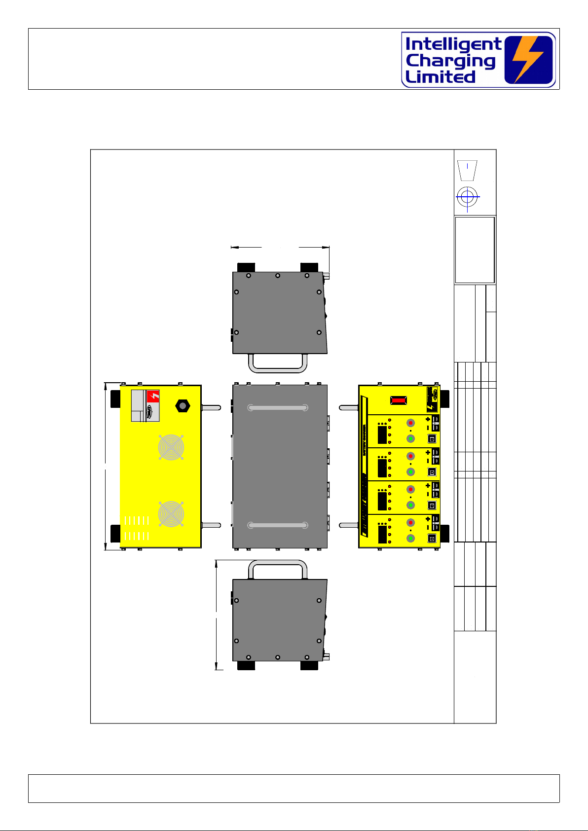
Weight 12Kg
Size 373mm Wide 245mm Height 219mm Depth
All specifications are subject to change.
Doc: DWG1057-09-R2 SBSC11Q Operators manual.o t Page 15 of 18 Copyright Material of Intelligent Charging Limited © 2018
Printed On : 17/07/19
SBSC11Q Four channel SLA Battery Charger
Operator Manual
10 General Arrangement
Doc: DWG1057-09-R2 SBSC11Q Operators manual.o t Page 16 of 18 Copyright Material of Intelligent Charging Limited © 2018
Printed On : 17/07/19
±
NOT SCALED
UNCLASSIFIED
SECURITY CLASSIFICATION
Drawing No SHEET
TITLE
CasC Syst ms Ltd.
Ford Hous , D wing Road
Rackh ath Industrial Estat
Norwich, Norfolk
NR13 6PS
TEL +44-(0)1603-722770 FAX +44-(0)1603-722771
EMAIL sal s@casc-ltd.com
CHECKED
DRAWN
MATERIAL
SCALE
UNITS
TOLERANCE
FINISH
CHANGE DESCRIPTION DATEISS
OF
COLOUR
METRIC
THIRD ANGLE
PROJECTION
CHANGE DESCRIPTION DATEISS
CJF
GC
28-06-2011
DWG1057-00
1
1 1
NA NA
NA
SBSC11Q GENERAL ARRANGEMENT
First Drawn.
.
.
.
.
.
.
.
.
. .
. .
.
.
.
.
.
.
.
.
.
.
.
.
.
.
.
.
SERIAL No:
INTELLIGENT CHARGING
from
Controlle Access Storage Ca binets Lt
For House, Dewing Roa ,
Rackheath In . Est. Norwich,
Norfolk, NR13 6PS, ENGLAND.
TEL: +44-1603 -722770
FAX: +44-16 03-72277 1
MAIL: sal [email protected]
C ARGING
INTELLIGENT
FROM
373.0 mm
244.5 mm
219.0 mm
10A
ERR
SBSC11Q
POWER
START STOP
OUTPUT #1
RUN DSUL
10A
10A
10A
Press To Reset Press To Reset Press To Reset Press To Reset
VOLTS
AMPS
TIME
TRIC ERR
START STOP
OUTPUT #2
RUN DSUL
VOLTS
AMPS
TIME
TRIC ERR
START STOP
OUTPUT #3
RUN DSUL
VOLTS
AMPS
TIME
TRIC ERR
START STOP
OUTPUT #4
RUN DSUL
VOLTS
AMPS
TIME
TRIC

SBSC11Q Four channel SLA Battery Charger
Operator Manual
11 Product Warranty
Your Intelligent Charging Limited product is guaranteed against faulty workmanship materials
and malfunction for a period of 12 months from the date of purchase, unless agreed otherwise
by Intelligent Charging Limited. Within this warranty period Intelligent Charging Limited will
undertake to repair or replace the product proved to be faulty.
We recommend you keep all packaging for the duration of the 12 month warranty, after which
you should dispose of all waste packaging in accordance with your local legislation
Products which have become faulty within the 12 month warranty period must be returned to
Intelligent Charging Limited, where Intelligent Charging Limited will then investigate the
warranty claim.
Intelligent Charging Limited products, when properly used, will render excellent service.
Therefore, users must read the User Manual and any other literature supplied with the product
carefully, and fully comply with all procedures shown in the literature and product training /
familiarisation sessions, as misuse or failure to follow the instructions may render this
warranty void.
This warranty is not transferable and excludes routine maintenance, consumables, parts
subject to normal wear and tear, service maintenance kits and damage caused by misuse or
negligence. Warranty claims attributable to improper, or careless, use or handling, and to
normal wear, are excluded from this warranty.
Intelligent Charging Limited only obligation shall be to repair or replace such products that
have proved to be faulty. Intelligent Charging Limited shall not be liable for any injury, loss or
damage, direct or consequential, arising out of the use, or the inability to use the product. The
customer shall determine the suitability of this product for its intended use, and the customer
assumes all risks and liability whatsoever in connection herewith.
Intelligent Charging Limited reserves the right to improve or modify this product
without prior notice.
Doc: DWG1057-09-R2 SBSC11Q Operators manual.o t Page 17 of 18 Copyright Material of Intelligent Charging Limited © 2018
Printed On : 17/07/19

SBSC11Q Four channel SLA Battery Charger
Operator Manual
This page is intentionally left blank.
Doc: DWG1057-09-R2 SBSC11Q Operators manual.o t Page 18 of 18 Copyright Material of Intelligent Charging Limited © 2018
Printed On : 17/07/19
Table of contents
Other Intelligent Charging Batteries Charger manuals


