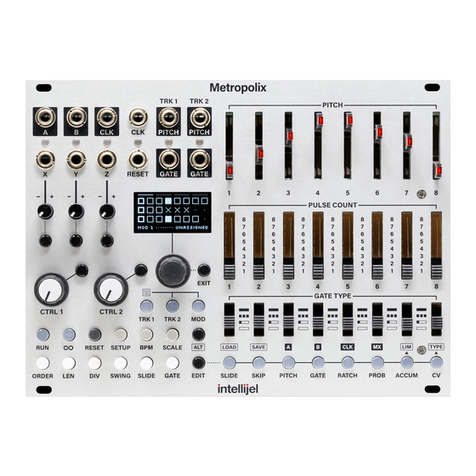
Intellijel Metropolis User manual

Metropolis Manual v1.30
Metropolis
Complex Multi-Stage Pitch and Gate Sequencer

MetropolisManualv1.30
TableofContents
Table of Contents
Overview
Features
Installation
Before Your Start
Installing Your Module
Front Panel
Menu Functions
Transport Functions
RUN
RESET
PREV
NEXT
Timing Functions
BPM
SWING
INT/EXT
DIV
Sequencer Functions
MODE
STAGES
STEP/DIV
SCALE
ROOT
System Configuration
AUX A / AUX B
SAVE
LOAD
CONFIG
OCT (Octaves)
d (Dividers)
SYn (Sync Mode)
rST (Reset Mode)
rPC (Rest Pitch)
ScAlE (Scale Shortcuts)
Page 1

MetropolisManualv1.30
ModES (Mode Shortcuts)
b (SLIDE/SKIP Button Function)
TunE (Tuning Mode)
CALIb (Calibration Mode)
Vr (Version Display)
Shortcut Keys
SWING
DIV
SAVE
LOAD
MODE
STAGES
STEP/DIV
SCALE
Patch Examples
Basic Patch
Modulated Sequence
Firmware Updates
Technical Specifications
Page 2

MetropolisManualv1.30
Overview
The Intellijel Metropolis is a unique and powerful Eurorack format musical sequencer
inspired by the Ryk M-185 (a Roland System 100m format sequencer.) but with many
additional enhancements and functions.
The Metropolis comprises eight STAGES, each with its own assignable gate mode,
pulse count, ratchet count, and pitch value. Each stage can also have slide or skip
activated. The slide functionality is a constant time portamento very similar to the
Roland TB303 which produces a very musical and interesting result.
In addition to the base sequencer settings set with the sliders and switches there is a
full menu of controls and auxiliary modifiers that allows the user to control and
manipulate the sequence in many powerful ways including sequencer direction modes,
pitch quantization and scale manipulators, clock dividers, shuffle and much more.
The operation of the Metropolis is optimized for live performance and jamming, with
quick button combos available to access all of the commonly used features. A pair of
AUX inputs allows modulation of the sequencer playback for even greater variation.
Features
● Sequencer modes: Forward, Forward-fixed, Reverse, Reverse-fixed, PingPong,
PingPong-Fixed, Random, Random-fixed, Brownian, Brownian-fixed
● TB-303 style slide (constant time portamento) with adjustable time.
● Internal quantizing in any key and a choice of 30 different scales
● Can act as a master clock with tap tempo BPM control or slave to an external clock.
● SAVE/LOAD panel settings to EEPROM
● Shuffle
● Internal clock divider
● Sync output
● Two assignable AUX inputs which can control: gate length, transpose, key shift, root
shift, sequence length, step divisor and octave offset.
● Config menu to set slider pitch range, clock div type, sync type and reset type
● All menu actions are one level deep. i.e. press the menu button and spin the encoder.
There are no hidden levels or sub menus (except for the CONFIG menu)
● All the core original RYK m185 functions. Read more about the original project here and
here
Page 3

MetropolisManualv1.30
Installation
Intellijel Eurorack modules are designed to be used with a Eurorack-compatible case and power
supply.
BeforeYourStart
Before installing a new module in your case you must ensure your case’s power supply has
sufficient available capacity to power the module:
● Sum up the specified +12V current draw for all modules, including the new one. Do the
same for the -12 V and +5V current draw. The current draw will be specified in the
manufacturer's technical specifications for each module.
● Compare each of the sums to specifications for your case’s power supply.
● Only proceed with installation if none of the values exceeds the power supply’s
specifications. Otherwise you must remove modules to free up capacity or upgrade your
power supply.
You will also need to ensure you have enough free space (hp) as well as free power headers in
your case to fit the new module.
You can use a tool like ModularGrid to assist in your planning. Failure to adequately power your
modules may result in damage to your modules or power supply. If you are unsure, please
contact us before proceeding.
InstallingYourModule
When installing or removing a module from your case always turn off the power to the case and
disconnect the power cable. Failure to do so may result in serious injury or equipment damage.
Ensure the 10-pin connector on the power cable is connected correctly to the module before
proceeding. The red stripe on the cable must line up with the -12V pins on the module’s power
connector. The pins are indicated with the label -12V, a white stripe next to the connector, the
words “red stripe”, or some combination of those indicators.
Page 4

MetropolisManualv1.30
Most modules will come with the cable already connected but it is good to double check the
orientation. Be aware that some modules may have headers that serve other purposes so
ensure the cable is connected to the right one.
The other end of the cable, with a 16-pin connector, connects to the power bus board of your
Eurorack case. Ensure the red stripe on the cable lines up with the -12V pins on the bus board.
On Intellijel power supplies the pins are labelled with the label “-12V” and a thick white stripe:
If you are using another manufacturer’s power supply, check their documentation for
instructions.
Page 5

MetropolisManualv1.30
Once connected, the cabling between the module and power supply should resemble the
picture below:
Before reconnecting power and turning on your modular system, double check that the ribbon
cable is fully seated on both ends and that all the pins are correctly aligned. If the pins are
misaligned in any direction or the ribbon is backwards you can cause damage to your module,
power supply, or other modules.
After you have confirmed all the connections, you can reconnect the power cable and turn on
your modular system. You should immediately check that all your modules have powered on
and are functioning correctly. If you notice any anomalies, turn your system off right away and
check your cabling again for mistakes.
Page 6

MetropolisManualv1.30
FrontPanel
Page 7

MetropolisManualv1.30
1. AUX A input - Patch a -5 to +5V source here for modulating the sequencer parameter
assigned to AUX A.
2. GATE output - The sequencer gate signal (0V for off, +5V for on) is produced here.
Typically you would patch this to the gate input of an ADSR or AHD envelope generator.
3. PITCH output - The pitch control voltage (CV) is produced here. This would usually be
patched to the 1V/Oct or PITCH/FM inputs of a VCO. The signal is in the range of 0-5V
and is scaled 1V/Oct.
4. SYNC output - A gate is produced here at either the first or last clock pulse in a
sequence depending on the SYNC setting in the CONFIG menu. The yellow LED
indicates the output state.
5. AUX B input - Patch a -5 to +5V source here for modulating the sequencer parameter
assigned to AUX B.
6. RESET input - Patch a gate signal (0 - 5V) to reset the sequencer on either the next
clock pulse or immediately, depending on the RESET option in the CONFIG menu.
7. CLK input - Patch an external clock source (0 - 5V logic level, or a pulse from an LFO)
here. This input is only active when external clock mode is selected from the INT/EXT
menu.
8. CLK output - When the Metropolis is in internal clock mode (INT CLK) the BPM based
clock is generated here. In external clock mode (EXT CLK) the external clock is divided
and produced at this output. This clock frequency is divided by a value set with the DIV
menu and is in a range of 1 (no division at all) to 32 (32 clock pulse internally must occur
before one clock pulse externally is generated). In the CONFIG menu DIV TYPE
submenu there is an option to change this output to generate a pulse at the beginning of
each new stage instead of acting as a clock output.
9. DISPLAY - All menu values and realtime sequencer data are displayed here.
10. BUTTON menu - This array of 18 buttons comprises the main configuration and controls
for the sequencer. They are colour-coded according to function:
○RED - Transport functions
○GREY - Timing functions
○ WHITE - Pattern function
○BLACK - System configuration
11. GATE TIME knob - This knob allows you to set the gate time from the shortest possible
(full counter-clockwise) to the longest (full clockwise). If one of the AUX inputs has been
assigned to G.LEn then the value set by this knob is summed with the aux modulation.
12. EXIT button - This button immediately exits any menu and returns to the default
sequencer display.
13. DATA encoder - This rotary encoder is for setting values under the different menus and
submenus. For menus where the selection is blinking, the encoder must be clicked to
confirm the selection or enter a submenu. In all other menus clicking the encoder returns
to the default sequencer display.
14. SLIDE TIME knob - This knob sets the pitch slide time for any sequence stage that has
slide activated. The time ranges from approximately 0 seconds (no slide) when fully
counter-clockwise to approximately 1 second when fully clockwise. This slide is constant
Page 8

MetropolisManualv1.30
time regardless of the pitch interval between the two stages, much like the classic
Roland TB-303.
15. SLIDE / SKIP buttons - These buttons have several functions:
○ Single click - activates the pitch glide for the selected stage. The LED will light as
solid green to indicate this is active.
○ Double click - activates skip fro the selected stage. The LED will blink to indicate
this is active.
○ Hold and turn encoder - Activates ratcheting for the selected stage. The display
will indicate the ratchet amount from 1 (no ratcheting) to 4.
○ Hold other button and single click - Activate the shortcut for the held button. See
the shortcuts section for more details.
16. GATE MODE switches - Each switch sets the gate mode for its respective stage, either
HOLD, REPEAT, SINGLE, or REST.
17. PULSE COUNT switches - Each of these switches sets the pulse count for the
associated stage in the range of 1 to 8.
18. PITCH sliders - Each of the sliders sets the pitch for the associated stage. The LED on
the slider indicates the current gate state for the stage when the sequence is running.
The slider position is quantized to a note in the current scale. The quantized note value
is shown on the display when the sequence is playing or when a slider is moved.
Page 9

MetropolisManualv1.30
PatternEditing
On the Metropolis a pattern consists of 8 stages. Each stage has 6 settings:
● PITCH - Is set by the PITCH sliders. The slider’s position is quantized to a note in the
current scale. When the sequencer advances to a new stage the PITCH output will
change to reflect that stage’s pitch, unless the stage is a REST or rPC (Rest Pitch) is
enabled in the CONFIG menu.
● PULSE COUNT - Is set by the PULSE COUNT switches. The pulse count determines
how many clock cycles the sequencer stays on a stage. For example is the sequencer is
currently on a stage with PULSE COUNT 1 it will advance to the next stage as
determined by the MODE upon the next clock. If the PULSE COUNT is 3, it will stay on
the stage for 3 clock cycles before advancing.
● GATE MODE - Each stage has four possible modes gate operation:
○HOLD - The gate output is held high for the number of clock pulses set by the
PULSE COUNT for the stage.
○REPEAT - The gate output is repeatedly pulsed based on the current STEP/DIV
setting and PULSE COUNT for the stage. If the PULSE COUNT is 1, then this
behaves the same as SINGLE. The length of time each gate is high is
determined by the GATE TIME knob.
○SINGLE - The gate goes high at the beginning of the first pulse in the stage for a
duration set by the GATE TIME knob.
○REST - The gate is held low for the number of clock pulses set by the PULSE
COUNT switch for that stage.
● SLIDE - When SLIDE is enabled for a stage the PITCH output will not immediately
change to the stage’s pitch. Instead, an analog pitch glide circuit is engaged that will
gradually slide the pitch over a period of time determined by the SLIDE TIME knob. A
stage with SLIDE activated will have its green LED lit.
● SKIP - When SKIP is enabled for a stage the sequencer skips over it to the next stage
when it comes time to advance. The stage’s PULSE COUNT doesn’t count towards the
total sequence length. A blinking green LED indicates a skipped stage.
● RATCHET - Each stage has a “ratchet” value from 1 to 4 that can be set by holding a
stage’s SLIDE / SKIP button and turning the encoder. The ratchet is a subdivision of a
pulse. With a value of 1, there is no subdivision. With a value of two, two gates will be
output for each pulse that would normally have one gate. The gate time of each is half
the setting of the GATE TIME knob. All ratchets can be cleared by holding any SLIDE /
SKIP button and clicking the encoder.
Patterns are also affected by the options described in the “Pattern Functions” section. Patterns
can be saved and loaded using the SAVE and LOAD buttons as described in the “Shortcut
Keys” section.
Page 10

MetropolisManualv1.30
MenuFunctions
TransportFunctions
RUN
Toggles the start / stop of the sequence.
RESET
Resets the sequence. The behaviour depends on the CONFIG -> RESET mode:
If rST_n then the reset occurs on the next clock pulse.
If rST_F then the reset occurs if the CLK input is high at the same time as the RST input is
high.
PREV
If the sequencer is running, stays on the current stage on the next clock pulse. If the sequencer
is stopped this button can be used to scroll forwards through the stages to preview the pitches.
NEXT
If the sequencer is running, skips the sequence ahead by one stage on the next clock pulse. If
the sequencer is stopped this button is used to scroll forwards through the stages to preview the
pitches.
TimingFunctions
BPM
When INT CLK mode is active you can use this button to set the rate of the internal clock from
20 to 320 bpm. Click the button once to enter the menu and then turn the ENCODER to adjust
the BPM. Alternatively you can tap the tempo on the BPM button.
When EXT CLK mode is active the BPM menu displays the rate of the external clock. The pulse
is also indicated by a blinking dot after the letters bP. Clicking the BPM button when already in
the menu locks the tempo for the purpose of gate length calculation. This is useful if you are
using an irregular clock but wish to have consistent gate lengths. After being locked, the tempo
can be further adjusted via the encoder. The tempo lock is indicated by a solid dot after the
letters bP, and can be deactivated by clicking the BPM button again.
Page 11

MetropolisManualv1.30
SWING
This menu sets the shuffle amount between successive clock pulses when in INT CLK mode.
Every odd numbered clock pulse will be delayed by a percentage of the current clock interval.
The swing ranges in value from 50 (0% swing) to 72 (33% swing). Shuffle also affects the gate
length so that even steps will have longer gates than odd steps.
INT/EXT
The INT/EXT button allows you to select between three clock modes:
● C_InT uses the Metropolis internal clock, with the tempo set in the BPM menu.
● C_EXT advances the sequencer each time it receives a trigger on the CLK input. The
interval between successive pulses determines the tempo and gate length, which can be
locked in the BPM menu,
● C_d24 is for syncing to DIN sync (Sync24) compatible devices. In this mode Metropolis
expects a 24PPQ clock on the CLK input and only runs when the RESET input is high.
The sequence is reset each time RESET goes low. The CLK input should be connected
to pin 1 of a DIN sync cable and the RESET input to pin 5.
In this menu the display flashes to indicate that your choice of clock mode is not active until you
click the encoder.
DIV
The DIV button accesses a menu composed of two flashing submenu choices. Select the
submenu by turning the ENCODER and then click the ENCODER to enter the menu.
● di - Incoming clock division. Divides the incoming or internal clock by a factor of 1 to 64.
When divided by 2, the sequencer will run at ½ speed, divided by 3 at ⅓ speed. Etc.
● do - Outgoing clock division. Divides the outgoing clock on the CLK output. The setting
in the CONFIG menu determines the allowable values:
○ d_ALL - Any division from 1 to 64.
○ d_Odd - Any odd division from 1 to 64, eg: [1, 3, 5, …].
○ d_EvE - Any even division from 1 to 64, eg: [1, 2, 4, …].
○ d_STA - No divider value can be set. Instead, a clock pulse is generated each
time the sequencer advances to a new stage.
PatternFunctions
MODE
The MODE menu is used to choose how the sequencer advances between stages:
● Frd - Forward Mode: The sequencer advances to each new stage in the forward
direction, starting at stage 1. The last stage is set in the STAGES menu.
Page 12

MetropolisManualv1.30
● rEv - Reverse Mode: The sequencer advances to each new stage in the reverse
direction starting at the stage of the sequence set in the STAGES menu.
● PnG - Ping-Pong Mode: The sequence advances first in the forward direction starting at
stage 1 until it reaches the stage set in the STAGES menu. It then switches direction to
advance in reverse until it reaches stage 1 again.
● brn - Brownian Mode: This mode advances in a pseudo-random pattern known as a
“drunken walk”. Starting at stage 1 it has a 50% chance of moving forward, 25% chance
of staying at the same stage, and 25% chance of moving backwards. This results in a
sequence that generally trends forward with some repetition. The STAGES menu sets
the total number of stages before resetting to stage 1.
● rnd - Random Mode: The sequencer advances to each stage in a random order. The
STAGES menu sets the total number of stages to be included in the random choices.
E.g. if STAGES is 4 then only the first four stages of the sequence are considered.
● Frd-F - Fixed Forward Mode: The same as Frd mode except that the STAGES button
sets the total number of pulses
.
This is useful to sync the length of the sequence to
another sequencer with a precise number of steps.
● rEv-F - Fixed Reverse Mode: The same as rEv mode that the STAGES button sets the
total number of pulses
.
● PnG-F - Fixed Ping-Pong Mode: The same as PnG mode that the STAGES button sets
the total number of pulses
.
● brn-F - Fixed Brownian Mode: The same as brn mode that the STAGES button sets the
total number of pulses
.
● rnd-F - Fixed Random Mode: The same as rnd mode that the STAGES button sets the
total number of pulses
.
STAGES
This menu sets the length of the sequence in terms of the number of STAGES or
PULSES depending on the direction MODE that is currently active.
STEP/DIV
The STEP/DIV value determines how many clock pulses form a single gate if the gate
mode for the stage is REPEAT. The range of values is 1 to 4 pulses.
● STEP1 - The gate output goes high on every clock pulse.
● STEP2 - The gate output goes high on every second clock pulse.
● STEP3 - The gate output goes high on every third clock pulse.
● STEP4 - The gate output goes high on every fourth clock pulse.
E.g. If the PULSE COUNT for a stage is ‘5’ and the STEP/DIV is ‘2’ then the result
would be three gates produced where the first two are each 2 clock pulses long (1/8th
notes) and the third would be a single clock pulse (1/16th).
Page 13

MetropolisManualv1.30
SCALE
This menu allows you to select one of the scales used to quantize the values of the sliders:
Scale
Display
Intervals
Chromatic
CHrOM
0, 1, 2, 3, 4, 5, 6, 7, 8, 9, 10, 11
Major
MAJOr
0, 2, 4, 5, 7, 9, 11
Minor
MInOr
0, 2, 3, 5, 7, 8, 10
Dorian
dOrIA
0, 2, 3, 5, 7, 9, 10
Mixolydian
MIXOL
0, 2, 4, 5, 7, 9, 10
Lydia
LYdIA
0, 2, 4, 6, 7, 9, 11
Phrygian
PHrYG
0, 1, 3, 5, 7, 8, 10
Locrian
LOCrI
0, 1, 3, 4, 7, 8, 10
Diminished
dIMIn
0, 1, 3, 4, 6, 7, 9, 10
Whole-Half
-HALF
0, 2, 3, 5, 6, 8, 9, 11
Whole Tone
-HOLE
0, 2, 4, 6, 8, 10
Minor Blues
bLUES
0, 3, 5, 6, 7, 10
Minor Pentatonic
PEnT-
0, 3, 5, 7, 10
Major Pentatonic
PEnTA
0, 2, 4, 7, 9
Harmonic Minor
HArMI
0, 2, 3, 5, 7, 8, 11
Melodic Minor
MELMI
0, 2, 3, 5, 7, 9, 11
Super Locrian
SULOC
0, 1, 3, 4, 6, 8, 10
Arabic / Bhairav
ArAbI
0, 1, 4, 5, 7, 8, 11
Hungarian Minor
HUnGA
0, 2, 3, 6, 7, 8, 11
Minor Gypsy
GYPSY
0, 1, 4, 5, 7, 8, 10
Hirojoshi
HIrOJ
0, 2, 3, 7, 8
In-Sen
InSEn
0, 1, 5, 7, 10
Page 14

MetropolisManualv1.30
Japanese / Iwato
JAPAn
0, 1, 5, 6, 10
Kumoi
KUMOI
0, 2, 3, 7, 9
Pelog
PELOG
0, 1, 3, 4, 7, 8
Spanish
SPAIn
0, 1, 3, 4, 5, 6, 8, 10
Tritone
3TOnE
0, 1, 4, 6, 7, 10
Prometheus
PrOME
0, 2, 4, 6, 9, 10
Augmented
AUGME
0, 3, 4, 7, 8, 11
Enigmatic
EnIGM
0, 1, 4, 6, 8, 10, 11
ROOT
In this menu you can set the root note of the currently active scale. If the the active scale is
CHROMATIC then changing the ROOT will have no perceivable effect.
SystemConfiguration
AUX A / AUX B
These buttons set the target of the AUX A and AUX B inputs, which can be used to modify the
sequencer behaviour.
● G.LEn - Alter the gate length. This value is summed with the position of the GATE TIME
knob.
● STAGE - Alter the number of sequence STAGES or pulses (if in a fixed mode) by +/- 16.
● STEPd - Change the STEP/DIV value by +/- 4
● d.In - Change the clock division of the incoming clock by +/- 32
● rATch - Offset the ratchet level of the currently playing step.
● P.PrE - Shift the sequence before
the quantizer, tracks 1V/octave.
● P.PrEL - Shift the sequence before
the quantizer by +/- 12 semitones. Suitable for use
with an LFO or other modulation source that is not pitch based.
● P.OCT - Shift the sequence +/- 4 octaves.
● P.PoST - Shift the sequence after
the quantizer. Tracks 1V/octave.
● P.PoSL - Shift the sequence after
the quantizer by +/- 12 semitones. Suitable for use
with an LFO or other modulation source that is not pitch based.
Page 15

MetropolisManualv1.30
● rooT - Shift the root note of the current scale. Tracks 1V/octave, but only takes into
account the pitch class. E.g. 0 and 1V are both considered no shift, 0.083 and 1.083 will
both shift by one semitone.
● rooTL - Shift the root note of the current scale by +/- 12 semitones.
Note that in order to use the 1V/octave transpose destination your AUX inputs need to be
calibrated. If you purchased a Metropolis with firmware 1.30 or later this will have been done at
the factory. Otherwise please follow the instructions in the CALib (Calibration Mode) section of
the CONFIG portion of the manual.
SAVE
The SAVE button enters a menu which allows you to save the system settings to one of 8 slots.
Turn the ENCODER to select the save slot and then click the ENCODER to commit the settings
to the EEPROM memory. The last saved slot is loaded the next time the power is turned on to
the sequencer.
LOAD
The LOAD buttons enters a menu that allows you to recall one of the 8 global settings slots
from the EEPROM memory. Turn the ENCODER to select the slot and then click the ENCODER
to load the settings.
CONFIG
The CONFIG button enters the configuration menu. Turn the ENCODER to select a
configuration option and then click the ENCODER to edit that option. When done editing either
click the ENCODER to return to the CONFIG menu or click EXIT to return to the default screen.
Each option is described in a subsection below.
OCT (Octaves)
Sets the octave range of the pitch sliders, from 1 to 3.
d (Dividers)
Restricts which divisions are available in DIV menu.
● d_ALL - All values from 1 to 64.
● d_Odd - Odd values, eg: [1, 3, 5, …].
● d_EvE - Even values, eg: [1, 2, 4, …].
● d_STA - A special mode where the CLK output goes high when the sequencer
advances to a new stage.
SYn (Sync Mode)
Sets the behaviour of the SYNC output.
Page 16

MetropolisManualv1.30
● SYn_F - The sync pulse rises on the first clock pulse of the first stage of the sequence.
● SYn_L - The sync pulse rises on the last clock pulse of the last stage of the sequence.
rST (Reset Mode)
Sets the behaviour of the RESET input.
● rST_F - The sequencer resets immediately when the reset signal is high at the same
time as the clock.
● rST_n - The sequencer will reset on the next clock pulse. This mode is useful if your
DAW sends a reset signal when you stop the DAW clock clock and you want the
sequencer to start at 1 when you restart.
● rST_r - The RESET input functions as a “run” input. The sequencer runs when the gate
is high, but stops and resets when the gate is low. Some MIDI modules such as the
Intellijel µMIDI provide a way to interpret MIDI Start and Stop messages as a gate.
rPC (Rest Pitch)
Sets the PITCH output behaviour for stages that are set to REST mode.
● rPC_Y - The PITCH output is updated on rest stages.
● rPC_n - The PITCH output is not updated for rest stages.
ScAlE (Scale Shortcuts)
Configures the scales used in conjunction with the SCALE shortcut key. Upon entering the
submenu one of the SLIDE / SKIP LEDs will begin to blink to indicate the shortcut currently
being edited. You can select a scale for this shortcut by turning the ENCODER. To edit another
shortcut key, push the corresponding SLIDE / SKIP button.
ModES (Mode Shortcuts)
Configures the modes used in conjunction with the MODE shortcut key. Upon entering the
submenu one of the SLIDE / SKIP LEDs will begin to blink to indicate the shortcut currently
being edited. You can select a mode for this shortcut by turning the ENCODER. To edit another
shortcut key, push the corresponding SLIDE / SKIP button.
b (SLIDE/SKIP Button Function)
This sets the single / double click behaviour of the SLIDE / SKIP buttons.
● bSLId - A single click toggles slide, a double click toggles skip.
● bSKIP - A single click toggles skip, a double click toggles slide.
TunE (Tuning Mode)
Upon clicking the ENCODER to enter this menu, the Metropolis enters “tuning mode”. The pitch
output produces 0 V and the gate goes high. This is useful for tuning the base pitch of your
oscillator which is connected to the Metropolis. Click the ENCODER again to exit tuning mode.
Page 17

MetropolisManualv1.30
CALIb (Aux Calibration Mode)
Starts the 1V/octave calibration of the AUX A and AUX B inputs. The calibration is required to
effectively use the 1V/octave transposition modes of the auxiliary inputs.
The calibration process requires a tuned voltage source that can precisely output 0V and 1V. A
MIDI-CV interface or quantizer is suitable for this purpose.
● When this menu is entered the display will indicate CALA0.
● Connect the voltage source set to 0V to the AUX A input, turn the input attenuator fully
clockwise, and click the ENCODER.
● The display will now indicate CALA1. Set the voltage source to 1V and click the
ENCODER.
● The display will now indicate CALb0. Set the voltage source to 0V, connect it to the AUX
B input, turn the input attenuator fully clockwise, and click the ENCODER.
● The display will now indicate CALb1. Set the voltage source to 1V and click the
ENCODER.
● The calibration is now complete and stored in the EEPROM.
Vr (Version Display)
Displays the current firmware version, eg: 1.30.
Page 18

MetropolisManualv1.30
ShortcutKeys
A new feature in Metropolis 1.30 is that some of the menu buttons can also double as shortcut
keys to enable instant access to commonly used settings without having to enter a menu and
use the encoder. To use a menu button as a shortcut, press and hold
the button (eg: MODE)
and then press one of the SLIDE / SKIP buttons.
SWING
Selects between 8 commonly used swing settings. The values range from no swing (50%) at
button 1 to 64% at button 8, in increments of 2%.
DIV
Sets the incoming clock divider to a value equal to the button, 1 through 8.
SAVE
Saves the current sequence to a slot 1 through 8. The saved sequences are stored to the
internal EEPROM and persist even when Metropolis is powered down. A sequence can be
recalled using the LOAD button. A saved sequence contains all the values of PITCH, PULSE
COUNT, GATE MODE, SLIDE, SKIP, RATCHET, MODE, STAGES, STEP/DIV, SCALE and
ROOT. Once saved the display will indicate SPAT# (Saved Pattern #), where # is the number of
the saved pattern.
LOAD
Loads a sequence from slot 1 through 8. The display will indicate LPAT# (Loaded Pattern #)
where # is the number of the loaded pattern. Furthermore a dot will blink between the currently
playing note name and the animation on the right side of the display to indicate that Metropolis
is playing from a loaded sequence.
A loaded sequence replaces all the current values of PITCH, PULSE COUNT, GATE MODE,
SLIDE, SKIP, RATCHET, MODE, STAGES, STEP/DIV, SCALE and ROOT. Since the PITCH,
PULSE COUNT, and GATE MODE sliders can’t be moved by the CPU, they are not updated to
match the values in the sequence. If these controls are moved they will immediately override the
loaded value of the sequence. This is called “jump mode” on many synthesizers.
To “unload” the pattern and return all pitches, pulse counts, and gate modes to their physical
reality you can hold LOAD and push EXIT. The display will indicate PAnEL.
Page 19
Table of contents
Other Intellijel Recording Equipment manuals
Intellijel
Intellijel MIDI1U User manual
Intellijel
Intellijel Scales User manual
Intellijel
Intellijel Palette 104 User manual
Intellijel
Intellijel XFADE 1U User manual
Intellijel
Intellijel CYLONYX Rainmaker User manual
Intellijel
Intellijel Passive LPG 1U User manual
Intellijel
Intellijel Planar2 User manual
Intellijel
Intellijel Shifty User manual
Intellijel
Intellijel Audio I/O v3 2023 User manual

Intellijel
Intellijel Quadrax User manual

