Intellijel Metropolix User manual

Metropolix
Multitrack, Performance-Oriented
Pitch, Gate and Mod Sequencer
Manual (English)
Firmware Version: 1.0.0.5 | Revision: 2021.02.14 (PRELIMINARY)

TABLE OF CONTENTS
COMPLIANCE 5
INSTALLATION 6
Installing Your Module 7
Connecting an Optional Expander Module 8
METROPOLIX OVERVIEW 9
MANUAL CONVENTIONS 10
FRONT PANEL OVERVIEW 11
OUTPUTS 12
INPUTS 13
SECTIONS 14
PITCH SLIDERS 15
PULSE COUNT 17
GATE TYPES 18
SCREEN & TRACK BUTTONS 19
SCREEN 19
ENCODER 20
EXIT 21
HOME Screen 1 : Positions Overview 22
HOME Screen 2 : Note Overview 23
HOME Screen 3: Panel Values & Preset Overrides 24
HOME Screen 4: MOD Overview 25
TRACK BUTTONS 26
Selecting Tracks 26
Track Menu 27
Track Menu Options for Tracks 1 & 2 28
Lane Menu Options for the MOD Lanes 30
Metropolix Manual 1

TRANSPORT BUTTONS 31
RUN 31
RESET 31
LOOPY (∞) 32
Enter and Configure Loopy Mode 33
1-Finger Loopy 34
2-Finger Loopy 35
Stage Player 37
Loopy Latching 38
Muting Tracks and MOD Lanes 39
GLOBAL SETTINGS 40
SETUP 41
Factory Menu 47
BPM 48
SCALE 50
Customizing SCALE Shortcuts 52
TRACK SETTINGS 53
ORDER 54
Order Options 55
Customizing ORDER Shortcuts 58
LEN (LENGTH) 59
DIV 61
SWING 63
SLIDE TIME 64
(TRACK) GATE 66
Metropolix Manual 2

STAGE BUTTONS 69
SLIDE 70
SKIP 71
PITCH 72
(STAGE) GATE 74
RATCH 76
Ratcheting with Gate Stretching = OFF 77
Ratcheting with Gate Stretching = ON 78
PROB 81
ACCUM 83
Range Limits 85
Interaction with Gate Modes and Ratchets 85
CV 85
CV TYPE = CV Value 87
CV TYPE = Gate Toggle 89
ALT BUTTONS 90
LOAD 90
Loading Presets 91
SAVE 93
Saving Presets 94
Clearing Presets 94
OUT A & B 95
CLK 98
MX 100
LIM (ACCUM LIMITS) 104
TYPE (CV TYPE) 105
Metropolix Manual 3

THE MOD LANES 106
Selecting a MOD Lane to Edit 106
Editing Stage Voltage in a MOD Lane 107
Editing Gates in a MOD Lane 109
Assigning a MOD Lane to an OUT Jack 110
Assigning a MOD Lane to an Internal Parameter 111
Assigning Order, Length & Clock Div to MOD Lanes 114
CONTROL KNOBS 115
Control Knob Destinations 118
AUX INPUT SETTINGS 121
AUX & MOD DESTINATIONS 124
COPY & PASTE 129
GATE STRETCHING - EXAMPLES 131
CALIBRATION 133
Entering Calibration Mode 133
Calibrating Metropolix Outputs 134
Calibrating Metropolix Inputs 135
FACTORY RESET 136
FIRMWARE UPDATES 137
Firmware Change Log 137
TECHNICAL SPECIFICATIONS 137
Metropolix Manual 4

COMPLIANCE
Metropolix Manual 5
This device complies with Part 15 of the FCC Rules. Operation is subject to
the following two conditions: (1) this device may not cause harmful
interference, and (2) this device must accept any interference received,
including interference that may cause undesired operation.
Changes or modifications not expressly approved by Intellijel Designs, Inc.
could void the user’s authority to operate the equipment.
Any digital equipment has been tested and found to comply with the limits for a
Class A digital device, pursuant to part 15 of the FCC Rules. These limits are
designed to provide reasonable protection against harmful interference when
the equipment is operated in a commercial environment. This equipment
generates, uses, and can radiate radio frequency energy and, if not installed
and used in accordance with the instruction manual, may cause harmful
interference to radio communications.
This device meets the requirements of the following standards and directives:
EMC: 2014/30/EU
EN55032:2015 ; EN55103-2:2009 (EN55024) ; EN61000-3-2 ; EN61000-3-3
Low Voltage: 2014/35/EU
EN 60065:2002+A1:2006+A11:2008+A2:2010+A12:2011
RoHS2: 2011/65/EU
WEEE: 2012/19/EU

INSTALLATION
Intellijel Eurorack modules are designed to be used with a Eurorack-compatible case and power
supply. We recommend you use Intellijel cases and power supplies.
Before installing a new module in your case, you must ensure your power supply has a free power
header and sufficient available capacity to power the module:
● Sum up the specified +12V current draw for all modules, including the new one. Do the same for
the -12 V and +5V current draw. The current draw will be specified in the manufacturer's
technical specifications for each module.
● Compare each of the sums to specifications for your case’s power supply.
● Only proceed with installation if none of the values exceeds the power supply’s specifications.
Otherwise you must remove modules to free up capacity or upgrade your power supply.
You will also need to ensure your case has enough free space (hp) to fit the new module. To
prevent screws or other debris from falling into the case and shorting any electrical contacts, do not
leave gaps between adjacent modules, and cover all unused areas with blank panels. Similarly, do
not use open frames or any other enclosure that exposes the backside of any module or the power
distribution board.
You can use a tool like ModularGrid to assist in your planning. Failure to adequately power your
modules may result in damage to your modules or power supply. If you are unsure, please contact
us before proceeding.
Metropolix Manual 6

Installing Your Module
When installing or removing a module from your case always turn off the power to the case and
disconnect the power cable. Failure to do so may result in serious injury or equipment damage.
Ensure the 10-pin connector on the power cable is
connected correctly to the module before
proceeding. The red stripe on the cable must line up
with the -12V pins on the module’s power connector.
Different modules use different ways to indicate the
-12V pins. Some may be labelled with “-12V;” a white
stripe next to the -12V pins; the words “red stripe;” or
some combination of these. Additionally, some
modules may have shrouded headers, thus
preventing backward connections.
Most modules will come with the cable already
connected but it is good to double check the
orientation. Be aware that some modules may have
headers that serve other purposes so ensure the
power cable is connected to the right one.
The other end of the cable, with a 16-pin connector,
connects to the power bus board of your Eurorack
case. Ensure the red stripe on the cable lines up with
the -12V pins on the bus board. On Intellijel power
supplies the pins are labelled with the label “-12V”
and a thick white stripe. Sometimes the connectors
are shrouded, ensuring the cable can only be
oriented in one direction.
If you are using another manufacturer’s power
supply, check their documentation for instructions.
Metropolix Manual 7

Once connected, the cabling between the module and power supply should resemble the picture
below:
Before reconnecting power and
turning on your modular system,
double check that the ribbon cable is
fully seated on both ends and that all
the pins are correctly aligned. If the
pins are misaligned in any direction or
the ribbon is backwards you can
cause damage to your module, power
supply, or other modules.
After you have confirmed all the
connections, you can reconnect the
power cable and turn on your modular
system. You should immediately
check that all your modules have powered on and are functioning correctly. If you notice any
anomalies, turn your system off right away and check your cabling again for mistakes.
Connecting an Optional Expander Module
You can connect an Intellijel Gx (or Qx ) gate expander module to Metropolix to provide eight
additional gate and trigger outputs, which you configure via the MX button on the Metropolix panel.
1. Turn off power to your eurorack system.
2. Using the power power cable included with your expander module (Gx or Qx), connect one end
to the module’s 10-pin power connector and the other to the 16-pin power socket on your
eurorack system’s powered bus board — paying attention to polarity (aligning the red stripe as
described previously).
3. Using the I2C cable included with your expander module, connect one end to the module’s 6-pin
I2C connector and the other end to the I2C port on your Metropolix module. Both ports are
shrouded to ensure they can be connected in only one direction.
4. Power up your eurorack system.
IMPORTANT !!! : Always power down the modules before connecting or disconnecting an
I2C cable.
Metropolix Manual 8

METROPOLIX OVERVIEW
The Intellijel Metropolix is a unique and powerful Eurorack format musical sequencer, which evolves
and expands upon the real-time, hands-on, dynamic sequencing methodology first introduced in the
Intellijel Metropolis (which was, itself, inspired by the original Ryk M-185 — a Roland System 100m
format sequencer).
On first blush, it appears to be a simple 8-stage sequencer — but there is far more functionality
than first meets the eye:
● There are two tracks (TRK 1 and TRK 2) that are variants of the single master pitch/gate
sequencer, which is programmed via the PITCH sliders, PULSE COUNT and GATE TYPE
switches. Each track interprets the master sequence in a variety of ways — creating
complementary sequence variations that enable you to generate counterpoint, polyrhythms, and
all manner of sonic movement (both subtle and extreme).
Each of these tracks has its own playback ORDER, sequence LENgth, clock DIVision, SWING
amount, SLIDE time, and track GATE lengths. Other track-based sequence variables are
accessible from the TRACK MENU, and include Pitch Slider inversion; sequence note range;
track transposition; and more. In addition, Tracks 1 & 2 both have multiple lanes of per-stage
playback parameters, including: GATE override; PITCH override; RATCHet count; PROBability
of playback; ACCUMulating transposition, and a dedicated CV lane. Each stage also has a
SKIP feature, and a pitch SLIDE option.
● 8 separate and individual MODulation lanes are accessed via the MOD button. Each MOD lane
has 8-stages of modulation values and its own playback ORDER, LENgth, and clock DIVision;
and each lane is routable to one of Metropolix’ two assignable outputs or to dozens of internal
destinations, allowing for some sophisticated and powerful self-modulation.
● A trio of AUX inputs allows for external modulation of user-assignable sequencer parameters for
even greater variation, while two assignable CTRL knobs give you direct access to the
parameters you want to adjust most frequently during a performance. With dedicated Pitch/Gate
outputs for both Track 1 and Track 2; two totally user-assignable outputs (A and B); and internal
MOD routing, Metropolix features a wealth of patching opportunities.
● Metropolix also features a Loopy mode, allowing you to instantly play back short
sub-sequences, or even “play” the stage buttons directly (like a ‘keyboard’).
Metropolix Manual 9

● Metropolix stores up to 64 preset configurations (in 8 banks of 8 presets), and all live settings
are stored in EPROM, ensuring that your Metropolix will always power up exactly as you left it
— even if you haven’t saved them to a preset. By default presets can change all the structural
(menu-based) elements of your sequencer without overwriting the front panel controls, but full
recall is also available.
● The operation of the Metropolix is optimized for live performance and jamming, with quick
access to all the most important performance parameters, and the ability to greatly affect your
sequences with a single slider or switch.
MANUAL CONVENTIONS
●Bold text = BUTTON names and JACK names.
●Monospace text = Screen Parameter NAMES
● ‘Quoted’ text = Parameter ‘values’
● When told to long-press a button, it means to press the button down and hold it for
approximately 1 second. Some buttons have secondary functions, and long-pressing a button is
the way to access these secondary functions.
● When told to press-hold or press-and-hold a button, it means to press a button and continue to
hold it down while pressing a second button.
Metropolix Manual 10

FRONT PANEL OVERVIEW
The Front Panel consists of numerous input and output jacks, plus a plethora of buttons, switches,
knobs, and other such controllers.
Each of these is described briefly below, though more detailed descriptions are contained later in
the manual.
Metropolix Manual 11

OUTPUTS
[A] A OUT - The first of two user assignable signals is sent out this jack. To assign a signal to this
jack, press the ALT button to enter ALT mode, then press the A (Stage 3) button, as
described in OUT A & B , later in this manual.
The color of the output LED changes depending on the type of signal it carries
( blue = pitch/root data; yellow = gate/trigger; green (+) / red (-) = continuous voltage).
[B] B OUT - The second of two user assignable signals is sent out this jack. To assign a signal to
this jack, press the ALT button to enter ALT mode, then press the B (Stage 4) button, as
described in OUT A & B , later in this manual. As with the A output, the color of its
corresponding LED indicates the type of signal assigned to it.
[C] CLOCK OUT - Outputs a clock from Metropolix. A clock signal is output only when the
sequencer is running. The output clock can run at any division of the input (whether internally
or externally clocked), as set by the Clk Div parameter accessed via the ALT + CLK
(Stage 5) button, as discussed in CLK , later in this manual.
[D] TRACK 1 PITCH OUT - By default, the 1 V/Oct pitch generated by Track 1 is sent out this
jack. However, it’s possible to swap Track assignments, such that Track 2’s pitch is sent to this
jack. This feature (called Trk Out Swap ) can be assigned to a CTRL knob or an AUX input or
MOD Lane .
[E] TRACK 1 GATE OUT - By default, Track 1’s gate signal (off = 0V; on = +5V) is sent out this
jack. However, like with the PITCH out, you can swap it to carry Track 2’s gate output instead.
The corresponding LED lights whenever the gate output is high (on).
[F] TRACK 2 PITCH OUT - By default, the 1 V/Oct pitch generated by Track 2 is sent out this
jack. However, it’s possible to swap Track assignments, such that Track 1’s pitch is sent to this
jack. This feature (called Trk Out Swap ) can be assigned to a CTRL knob or an AUX input or
MOD Lane .
[G] TRACK 2 GATE OUT - By default, Track 2’s gate signal (off = 0V; on = +5V) is sent out this
jack. However, like with the PITCH output, you can swap it to carry Track 1’s gate output
instead. The corresponding LED lights whenever the gate output is high (on).
Metropolix Manual 12

INPUTS
[H] CLOCK IN - Patch an external clock source here. This input is used to synchronize Metropolix
playback to an external signal source, and requires that Metropolex be clocked externally
(which is enabled by pressing the SETUP button, and setting Clock to ‘External’).
NOTE: The Clock IN LED blinks in time with the clock division being applied to this incoming
external clock (as set with the ExtClockDiv parameter on the BPM screen, when
Clock = ’External’. The LED does not blink if the internal clock is used.
[I] RESET IN - By default, a trigger signal patched into this jack will reset the current sequence to
its beginning stage.
You can program individual tracks to ignore the RESET trigger by going to the TRACK MENU ,
and setting the Global Reset option to ‘Off.’
Using the SETUP MENU , you can reconfigure the jack to act as a RUN input (instead of a
RESET input). In this configuration, the sequence plays while the input gate signal is high, and
it doesn’t play when the gate signal is low.
NOTE: The LED above the RESET jack flashes red each time the sequence resets.
[X] X IN - One of three AUX inputs for controlling Metropolix. Patch a control voltage source (-5V
to +5V) into this jack to modulate whichever sequencer parameter is assigned to that jack.
See AUX Input Settings to learn how to assign parameters to the X IN jack, and what those
various parameters accomplish.
[Y] Y IN - A second AUX input for controlling Metropolix. It is functionally identical to the X IN .
[Z] Z IN - A third AUX input for controlling Metropolix. It, too, is functionally identical to X IN .
Metropolix Manual 13

SECTIONS
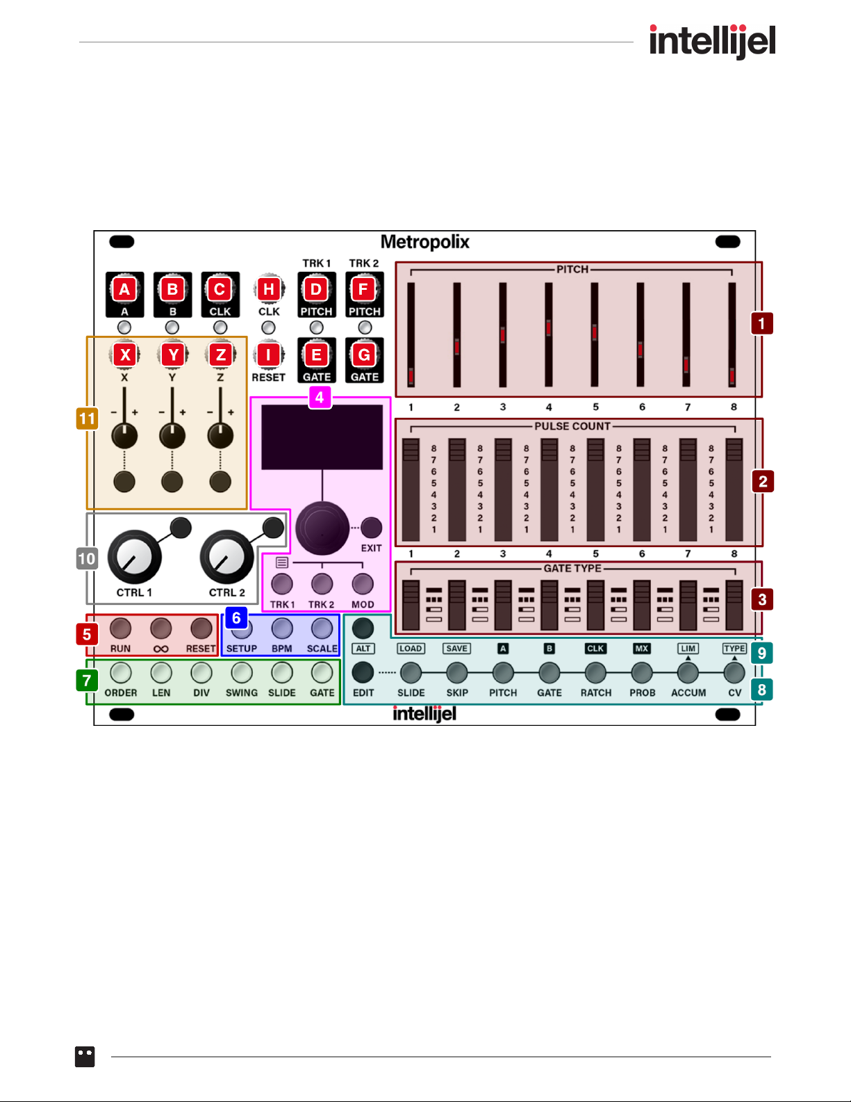
In order to understand all the various control features, let’s first look at how they’re grouped:
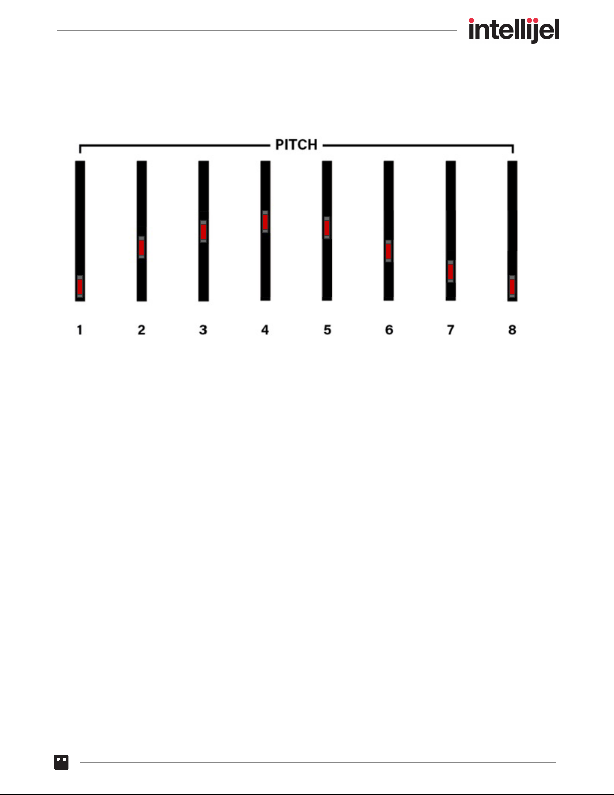
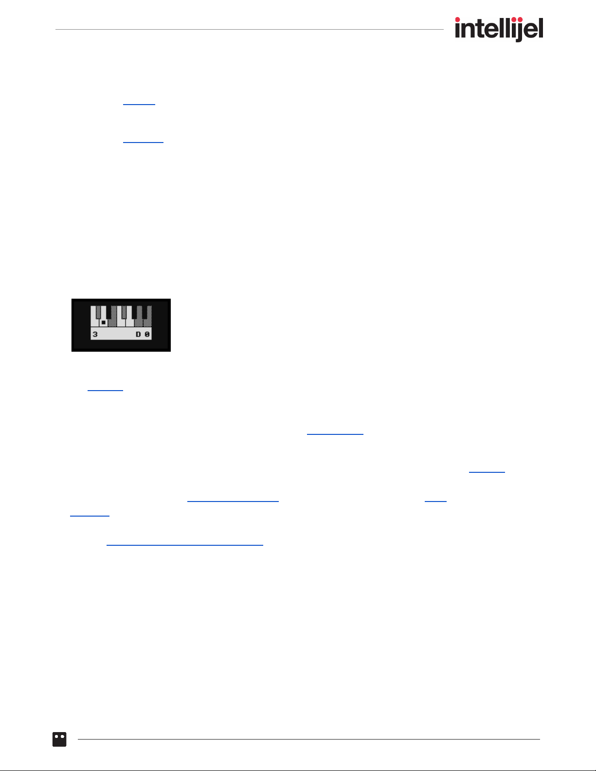
[1] PITCH sliders - These eight sliders control the pitch played by the associated stage. See
PITCH SLIDERS for more information.
[2] PULSE COUNT switches - Each of these switches sets the pulse count (from 1 to 8 pulses)
for the corresponding stage. This determines how long the stage plays in relation to all the
other stages. See PULSE COUNT for more information.
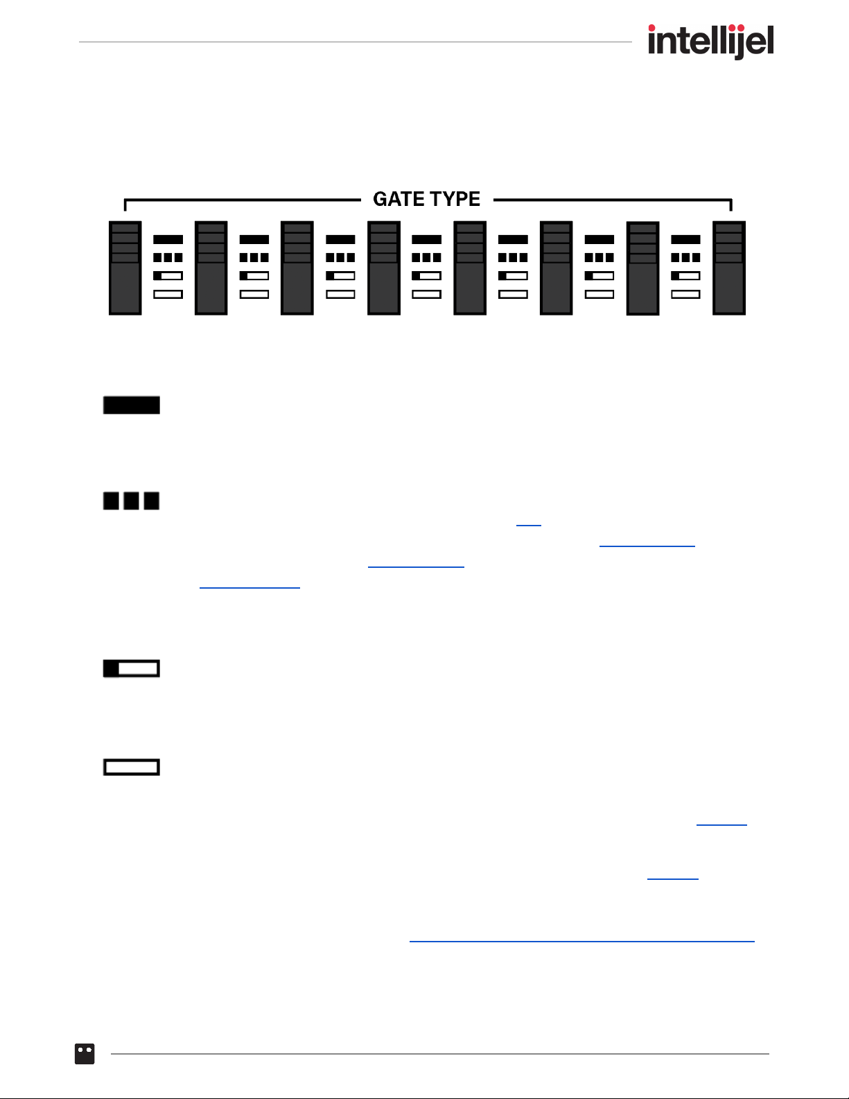
[3] GATE TYPE switches - Each switch sets the gate type for its respective stage, either HOLD,
MULTIPLE, SINGLE, or REST as discussed in GATE TYPES , later in this manual.
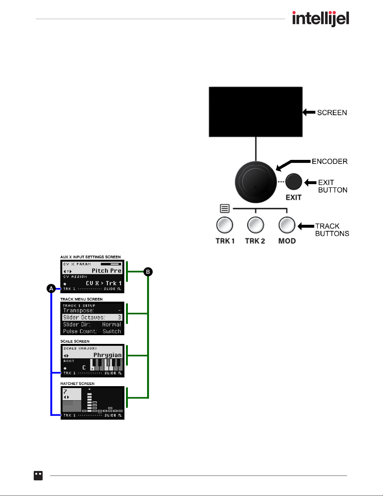
[4] SCREEN & TRACK BUTTONS - This section, discussed in SCREEN & TRACK BUTTONS ,
contains a SCREEN and PUSH-ENCODER for setting and viewing Metropolix functions; three
TRACK buttons for selecting which track you wish to edit; and an EXIT button, which steps
you back through any Metropolix menus or modes or (if long-pressed) takes you immediately
to Metropolix’s top-level HOME Screen.
[5] TRANSPORT Buttons - These buttons control Metropolix’s transport, enabling you to start
and stop playback, reset the sequencer to its ‘starting’ position, and enter Loopy mode. See
TRANSPORT BUTTONS for a detailed description.
[6] GLOBAL SETTINGS - These buttons control various functions that apply to Metropolix as a
whole — operating across all tracks. See GLOBAL SETTINGS for a detailed description of all
the GLOBAL SETTINGS buttons.
[7] TRACK SETTINGS - These buttons modify the track that’s currently selected for editing.
Tracks are selected by pressing (and lighting) the corresponding TRACK button in the
SCREEN & TRACK BUTTONS section. See TRACK SETTINGS for a detailed description of
all the TRACK SETTINGS buttons.
[8] STAGE Buttons - These buttons modify different settings on a stage-by-stage basis within
individual tracks. See STAGE BUTTONS for a detailed description of every STAGE function.
[9] ALT Buttons - Each Stage button has an alternate function, indicated by the text above the
button, which is accessed by pressing the ALT button prior to pressing the Stage button. See
ALT BUTTONS for a detailed description of all the ALT functions.
[10] CTRL (Control) Knobs - Assign functions to each of these knobs for real-time changes
during a performance. See Control Knobs for a detailed description of these knobs.
[11] AUX IN Settings - Metropolix offers three user-assignable AUX inputs ( X , Y and Z ) for
controlling the sequencer externally. Press an input’s corresponding button to assign an AUX
destination on one or more tracks, and use the built-in attenuverter to dial in the desired
amount of control. For more information, see AUX Input Settings .
Metropolix Manual 14

PITCH SLIDERS
(SECTION 1)
These sliders determine the default pitch value of each corresponding stage. Metropolix uses the
position of these sliders as a starting point for determining the actual pitch output by each stage on
each track.
On a GLOBAL level:
● Via the SCALE button, you can assign a scale type and root note to any quantized slider.
● Via the SETUP button, you can define which note represents the bottom of the slider (either a
“C” or the current scale’s root note).
On a per-TRACK level (accessed via the TRACK MENU ), you can assign:
● The pitch range of the slider (from 1 octave bottom-to-top, to 4 octaves bottom-to-top)
● Whether the slider’s lowest pitch is at the bottom (normal) or at the top (inverted).
● An overall output transposition above or below the default pitch value (±60 semitones).
Metropolix Manual 15

On a per-STAGE, per-TRACK level:
● Via the PITCH button, you can assign a note value that deviates from the slider’s current
position for each stage on each track.
● Via the ACCUM button, you can assign whether a stage’s pitch transposes cumulatively (either
with each pass through the stage; each pulse within a stage; or each ratchet).
The way in which a slider’s position can be interpreted, inverted, transposed and overridden by the
various tracks and stages allows Metropolix to create harmonic intervals and counterpoint that
change and evolve with a single move of a slider.
Each pitch slider has an LED that lights to indicate which stage is playing — glowing brightest when
the stage’s gate is high and dimmer with the stage’s gate is low.
When you move a pitch slider, the value will be shown briefly on the screen, enabling you to set
pitch values quickly and precisely.
The keyboard ‘greys out’ any notes not contained within the root/scale assignment you make with
the SCALE button. That is, in-scale white keys are white; in-scale black keys are black; out-of scale
keys (black or white) are ‘grey.’ The note you select with the pitch slider is indicated by a dot (and
named beneath the keyboard, on the right). The Stage Number is shown beneath the keyboard on
the left. Note that setting a Transpose value in the Track Menu enables you to assign notes that are
out of scale.
NOTE: Metropolix offers the option of loading stored pitch values with a Preset in its SETUP menu.
If you choose to load this data, then the pitch you hear may not match the sliders. Similarly if a
Stage is programmed to override the PITCH , or it’s being modulated by an AUX input, or the
ACCUM function is operating, it too will override the slider. You can always see exactly which pitch
is playing by pressing the EXIT button (to view the HOME screens), then rotating the encoder to
display HOME Screen 2 : Note Overview .
Metropolix Manual 16

PULSE COUNT
(SECTION 2)
These switches set the number of clock pulses at which the sequencer stays on a particular stage.
In general, the sequence will not advance to the next stage until the chosen number of clock pulses
has passed. Each stage’s pulse count can be set from 1 pulse to 8 pulses.
EXAMPLE : If the sequencer is currently on a stage with PULSE COUNT = 1 it will advance to
the next stage (as determined by the ORDER screen) upon receipt of the next clock pulse. If the
stage’s PULSE COUNT = 3, it will stay on the stage for 3 clock pulses before advancing.
In general, the type (and number) of gates generated while on a stage is determined by the
GATE TYPE switches (described below).
NOTE: Metropolix offers the option of loading switch positions with a Preset in its SETUP menu. If
you choose to load this data, then the pulse count you hear may not match the switches. You can
always see the currently used switch setting by pressing the EXIT button (to view the HOME
screens), then rotating the encoder to display HOME Screen 3 : Panel Values & Preset Overrides .
Metropolix Manual 17

GATE TYPES
(SECTION 3)
These switches set the type of gate(s) generated by each stage. There are four possible types of
gates that a stage can generate:
HOLD - The gate goes high at the beginning of the first pulse in the stage, and remains
high for the number of clock pulses set by that stage’s PULSE COUNT switch. Because
the gate is still high when the sequence advances to the next stage, it will be tied (or
slurred) to the note on the following stage.
MULTIPLE - In general, a new gate is output for each pulse in the stage’s PULSE
COUNT (though the Pulse Div parameter in the DIV button can impact this). The
length of time that each pulse’s gate remains high is set by the (Track) GATE screen,
unless it’s overridden by the (Stage) GATE button or if Gate Stretching is turned on in
the TRACK MENU .
If a stage’s PULSE COUNT = 1, then a MULTIPLE type gate behaves the same as
SINGLE type gate, discussed below.
SINGLE - The gate goes high at the beginning of the first pulse in the stage, and
remains high for the pulse percentage duration set by the GATE TIME screen (unless it’s
overridden by a stage’s GATE button). Subsequent pulses in a stage’s PULSE COUNT
do not produce gates.
REST - The stage does not output a gate signal, keeping the gate low for the number of
clock pulses set by the stage’s PULSE COUNT switch.
NOTE : Ratchets can create additional gates within the time frame of a single pulse. See RATCH for
more information about the relationship between ratchets and Gate Type.
NOTE: Metropolix offers the option of loading switch positions with a Preset in its SETUP menu. If
you choose to load this data, then the Gate Type you hear may not match the switches. You can
always see the currently used switch setting by pressing the EXIT button (to view the HOME
screens), then rotating the encoder to display HOME Screen 3 : Panel Values & Preset Overrides .
Metropolix Manual 18

SCREEN & TRACK BUTTONS
(SECTION 4)
This section contains Metropolix’s screen,
push-encoder, three Track select button, and an
EXIT button.
SCREEN
The contents of the screen change dynamically as
you edit different Metropolix functions. Most editing
screens are accessed by pressing one of the many
buttons contained within the GLOBAL, TRACK,
and STAGE sections of the panel, and will be
discussed where appropriate.
In general, most screens have an upper section
that contains button-specific parameters; and a
lower section that contains the ACTION display.
For example, different screens are shown in the illustration on
the left: The common areas are:
[A] ACTION display : Common across most screens, this
area (in general) indicates the current function of the Stage
Edit buttons, though it will also indicate other temporary
actions, such as Shortcut selection or Copy/Paste operations.
[B] PARAMETER area : This area of the screen changes
depending on what is currently being edited, and will be
discussed in each relevant section.
Metropolix Manual 19
Table of contents
Other Intellijel Recording Equipment manuals

Intellijel
Intellijel MIDI1U User manual

Intellijel
Intellijel CYLONYX Rainmaker User manual

Intellijel
Intellijel Sealegs User manual

Intellijel
Intellijel Tangrams User manual

Intellijel
Intellijel Metropolis User manual

Intellijel
Intellijel MIDI 1U User manual

Intellijel
Intellijel Palette 104 User manual

Intellijel
Intellijel Steppy 1U User manual

Intellijel
Intellijel Steppy 3U User manual

Intellijel
Intellijel Quadrax User manual