Intellipet ZW18900-05 User manual

1
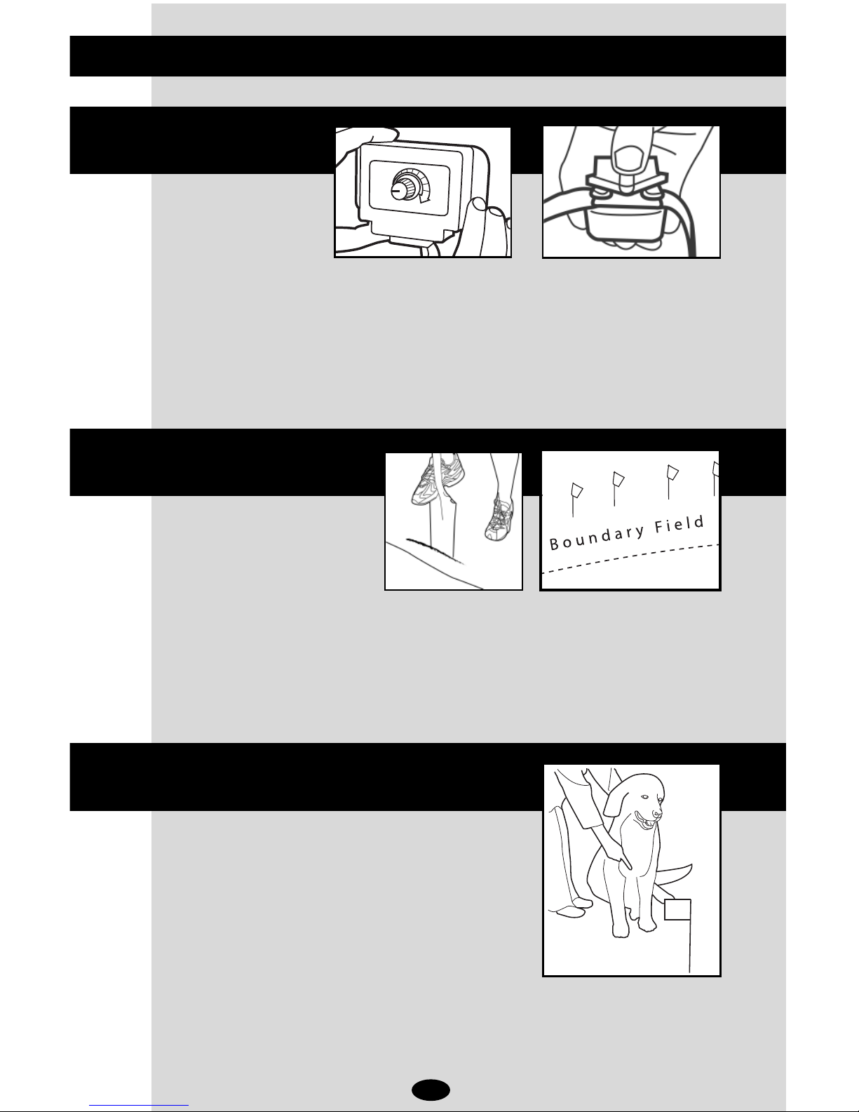
Step 2 Install the wall-mount transmitter
Step 1 Design your fence
Step 5 Power Up
uick Start Guide
Install batteries positive side out as shown.
Have the local utility companies mark your under-
ground lines. On a sheet of paper, draw your house
and yard. Draw a line around your property that
represents the containment area for your dog.
Most people find that the inside of an exterior wall of
a garage or basement is ideal. From the sample lay-
outs included, you can see the twisted wire running
from the house attaches directly to the transmitter.
Step 3 Layout the fence wire
Run the containment wire around the property as
outlined in your plan.
Step 4 Final connections
Splice the containment loop wires to the twisted
wire using the supplied waterproof splices.
Connect the other end of the twisted wire to the
wall-mount transmitter. Plug the AC adapter,
connect it to the transmitter and turn it on. The
red light should illuminate on the transmitter
indicating a successful loop.
Boundary
Wire
10’
10’
Buried Cable
90°
Boundary Wire
Splice
To wall-mount transmitter
2
Step 8 Train your dog
Step 7 Bury fence wire
Step 6 Test your fence
uick Start Guide continued
Set your FIELD WIDTH ADJUSTMENT NOB to the number 2 position. Using the
supplied test light, walk the dog’s collar up to the fence wire. Listen for the
warning tone and look for the test light to light. Try a number of different places
around the fenced area, in order to verify the range is consistent.
Dig the trench 1"-3” deep with a flat edge spade. Or, it is faster to use a gas-
powered edger. Digging the trench at an angle helps keep the wire in the ground
as you place it. Place Flags at edge of selected boundary field, where the warn-
ing tone is first heard – NOT at the wire.
Follow the training steps outlined in the Training and
Troubleshooting Guide. You may see your dog
respond immediately to the training, however con-
tinue to follow the Training Guide to fully train your
dog. The convenience that your new fence offers,
plus the added safety for your dog are well worth the
time invested.
This is the safety alert symbol. It is used to alert you to potential personal injury hazards. Obey all safety
messages that follow this symbol to avoid possible injury or death.
WARNING indicates a hazardous situation that, if not avoided, could result in death or serious injury.
CAUTION, used with the safety alert symbol, indicates a hazardous situation that, if not avoided, could
result in minor or moderate injury.
CAUTION, used without the safety alert symbol, indicates a hazardous situation that, if not avoided, could
result in harm to your pet.
NOTICE is used to address safe use practices not related to personal injury.
• Not for use with aggressive dogs. Do not use this product if your dog is prone to aggressive behavior.
Aggressive dogs can cause severe injury or death to their owners and others. If you are not sure that
this product is right for you r dog, please talk to your veterinarian or a certified trainer.
• Underground cables can carry high voltage. Have all underground cables marked before you dig to
bury your wire. In most areas this is a free service. Avoid these cables when you dig.
• Follow all safety instructions for your power tools. Be sure to always wear your safety goggles.
• Do not install, connect, or remove your system during a lightning storm. If the storm is close enough
for you to hear thunder, it is close enough to create hazardous surges.
• Risk of electric shock. Use the Fence Transmitter indoors in a dry location only.
Risk of injury. Wire on top of the ground may be a trip hazard; Place wires carefully.
This Intellipet™In-Ground Dog Fence is not a solid barrier. This system is designed to act as a deterrent
to remind pets by Static Stimulation to remain in the boundary established. It is important that you rein-
force training with your pet on a regular basis.
Proper fit of the collar is important. A collar worn for too long or made too tight on the pet’s neck may
cause skin damage. Ranging from redness to pressure ulcers; this condition is commonly known as bed
sores.
• Avoid leaving the collar on the dog for more than 12 hours per day.
• When possible reposition the collar on the pet’s neck every 1 to 2 hours.
• Check the fit to prevent excessive pressure; follow the instructions in this manual.
• Never connect a lead to the electronic collar; it will cause excessive pressure on the contacts.
• When using a separate collar for a lead, don’t put pressure on the electronic collar.
• Wash the dog’s neck area and the contacts of the collar weekly with a damp cloth.
• Examine the contact area daily for signs of a rash or a sore.
• If a rash or sore is found, discontinue use of the collar until the skin has healed.
• If the condition persists beyond 48 hours, see your veterinarian.
These steps will help keep your pet safe and comfortable. Millions of pets are comfortable while they
wear stainless steel contacts. Some pets are sensitive to contact pressure. You may find after some time
that your pet is very tolerant of the collar. If so, you may relax some of these precautions. It is important
to continue daily checks of the contact area. If redness or sores are found, discontinue use until the skin
has fully healed.
3
CAUTION
CAUTION
CAUTION
CAUTION
NOTICE
WARNING
WARNING
IMPORTANT SAFETY INFORMATION
Explanation of Attention Words and Symbols used in this guide

4
You may need to trim the hair in the area of the probes. Never shave the dog’s neck; this may lead to a
rash or infection.
• The Collar Receiver should not be on your dog when the system is tested. Your pet may receive an
unintended correction.
• The Boundary Width of the system must be tested whenever an adjustment is made to the contain-
ment field to prevent unintended corrections to your pet.
• If you use a collar and leash for training, be sure the extra collar does not put pressure on the con-
tacts.
• Always remove your dog’s Collar Receiver before performing any transmitter testing.
• Use care when mowing or trimming your grass not to cut the loop wire.
• For added protection unplug from the wall outlet and disconnect the loop boundary wires when
unused for long periods of time or prior to thunderstorms. This will prevent damage to the transmitter
due to surges.
• Always use the rubber insulators between the collar strap and probes to provide insulation in damp
conditions.
• Other collars and metal tags should be removed as they may interfere with proper operation.
• Do not attempt to dismantle or repair any components of this system; doing so will void the warranty
in full. The computerized circuitry should be serviced only by an authorized expert.
LIMITED WARRANTY
This product is warranted against defective material or workmanship for one year from the date of pur-
chase. Any product that is determined to be defective in material or workmanship during the warranty
period will be repaired or replaced without cost to the purchaser for parts or labor. Please contact
PetEdge Customer Service at 1-800-638-5754 regarding any defective product. PetEdge will not be
liable under this warranty for any defect, failure or malfunction of this product caused by normal wear,
abuse, misuse, unauthorized adjustments or repairs. PetEdge will not be liable for any incidental or con-
sequential damages of any type. Any implied warranty is limited to the one-year period provided in this
express warranty. Some states do not allow limitations on how long an implied warranty lasts or exclu-
sion or limitation of incidental or consequential damages, so the above limitations or exclusions may not
apply to you. Warranty is void if product has been modified in any manner, repaired by anyone other than
PetEdge or has been subject to unreasonable use. Warranty is valid in the United States.
Read the complete manual and follow all directions. This includes the Training and
Troubleshooting section. If you have questions, please call 1-800-638-5754.
This device is intended for use only on dogs. Never attempt to use it for any purpose not
described in this manual.
IMPORTANT ADVICE
CAUTION
NOTICE

5
EXTERNAL SURGE PROTECTOR
An External Lightning Protection Module helps protect
the transmitter from electrical power surges and light-
ning strikes near your boundary wire. A nearby lightning
strike can cause damage to your transmitter. Enhanced
lightning protection is available for the in-ground dog
fence by calling Intellipet™at 1-800-638-5754.
Lightning damage is not covered under your product
warranty unless external lightning protection is being
used.
Stimulation Settings
The stimulation is pre-set at the factory for optimal per-
formance. Should your dog enter the containment field
he/she will hear a two second warning tone. After train-
ing he/she will know to go back into the safe part of the
yard. By moving forward or staying in the same place,
the collar will deliver a continuous level of stimulation
until he/she moves back into the yard.
Over-Stimulation Prevention — In the unlikely event
that your dog becomes “trapped” in the containment
field, this feature limits stimulation duration to 10 sec-
onds. The system shuts off for 10 seconds before
resuming stimulation for another 10 seconds. This pat-
tern will repeat for a maximum of three cycles, a dura-
tion of 60-seconds.
Run-Through Prevention — Special features are incor-
porated in your system so your dog cannot “run-
through” the containment field without activating a
strong stimulation. The receiver automatically increases
the stimulation when your dog continues more than 1/3
of the way through the containment field, regardless of
the transmitter stimulation level setting. For example, if
the signal is detected 12 feet from the wire and your
dog enters the containment field, this feature is activat-
ed when he/she is approximately eight feet from the
wire. At this point, your dog automatically receives the
highest level of stimulation.
THE COLLAR RECEIVER
The collar receiver is attached to a nylon collar strap
that your dog will wear. The collar receiver administers
the warning tone and correction should your dog
attempt to leave the yard.
Fitting the collar on your dog.
The collar strap should fit snugly towards the top of your
dog’s neck with the collar receiver box on the bottom of
the neck. You should be able to get one finger between
the collar strap and your dog’s neck. The contact points
must make contact with the dog’s skin for proper opera-
tion. A little hair thinning may be required.
Important Notes:
A. Always use the rubber insulators and the collar strap.
They provide insulation in damp conditions and keep
the collar receiver secure.
B. A small amount of hair thinning or removal makes con-
tact with the dog’s skin easier.
C. This product is recommended for dogs six months of
age and older.
D. Occasionally, check the tightness of the receiver probes
to ensure the receiver does not fall off of the collar. Lost
collars are not covered under your warranty.
THE WALL-MOUNT TRANSMITTER
The transmitter is the system’s control center. The
transmitter sends a coded radio signal around the con-
tainment wire you will install.
1. Field Width Adjustment - Controls the distance from the
wire your dog can venture before hearing the warning
tone.
2. Internal Lightning/Surge Protection- Protects transmitter
from power surges or lightning strikes near the boundary
wire.
3. Loop Wire Terminals - Connections for the containment
wire.
4. Power Connection - Power for the containment system
supplied by the 12 volt adapter plugged into any 110v out-
let.
5. Power- Turn FIELD WIDTH NOB clockwise for ON, fully
counter-clockwise for OFF (until you hear click).
6. Yard Size Jumper- For system installations using 1,000
feet or more of wire (Your system comes with 500 Ft):
Remove four screws on front of transmitter. There are
jumper pins on the right side of the circuit board, move the
jumper to cover the pins next to the words LARGE. The
jumper must be installed for the system to operate.
7. System Indicator Light: System operating normally when
on. OFF indicates a malfunction.
IMPORTANT:
Intellipet™recommends that you unplug the transmitter
and disconnect the fence wire during lightning storms.

6
• Although the containment wire is only buried 1”- 3”
make sure you contact your utility company to mark
underground cables and wire before you dig.
• The containment wire must form a complete loop
from the transmitter.
• For your dog’s safety, it is recommended that you
keep the containment wire at least 10’ from the
street.
• eep in mind that you will want to place the wire
where there is room for an 8’-12’ containment field.
• Interference can occur around large metal objects
and buried electrical, telephone and cable TV wires.
Do not run closer than 10’ to these cables. You can
minimize interference issues by crossing perpendicu-
lar to these lines.
Front and Back Yard Loop
The most common installation. The wire is placed just
inside the property line to form a square or rectangle.
Hourglass Loop
Allows your dog to be contained in either the front or
back yard but not around the side of the house. When
the wire runs parallel to itself, as it goes toward the side
of the house, be sure the wires don’t come within 6’
feet of one another to avoid canceling the signal.
Double Loop
Confines your dog to the backyard only. The wire needs to
run around the backyard, using the house as a natural bar-
rier and doubling back to the transmitter to finish the com-
plete loop. When doubling back, make sure that there is at
least 6’ between the lines to avoid canceling the signal.
Step 1 Design your fence
splice
containment signal
cancelled in this area
Front and Back Yard Loop
Hourglass Design
Double Loop
splice
6 ft.
splice
7
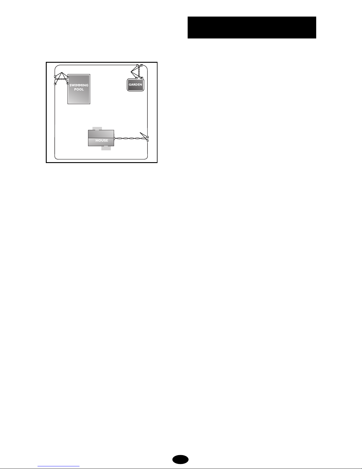
Customized Loops
You can create off limit areas, such as pools and gar-
dens by encircling the area with wire. Run twisted wire
from the fence loop to the encircled area and splice the
ends together. 1. Select a Location
Select an indoor, dry location to hang the wall-mount
transmitter. You will need a standard 110v grounded
outlet within 5 feet for power. Most people find the
inside of a exterior wall of a garage or basement
works well. You will need easy access to run the con-
tainment wire outside.
2. Hang transmitter on wall
Using the screw holes on the side of the transmitter
as a template, mark location of holes with a pencil.
Make sure the transmitter hangs straight and install
using supplied screws.
3. Provide for wire access to outside
You will need to get the wire from the transmitter to
outside where the containment loop will run. This can
be done through a window or you can drill a 1/4”
hole at the base of the wall to pass the wire through.
After final installation and testing is complete you can
caulk the hole to prevent water and insects from
entering.
Customized Design
splices splices
splices
Step 2 Install wall transmitter

8
With the transmitter installed and the hole drilled for the
wire, you can position the boundary wire that will form
your fence. DO NOT bury the wire until you are sure that
the system is running properly.
1. Amount of wire.
Your system includes 500 feet of boundary wire. For larger
areas, we offer a boundary kit with wire, flags and splices.
Here are some examples of wire coverage area:
2. Placing the wire
The wire must make a continuous loop from the trans-
mitter and back again. The signal is transmitted from
one terminal at the transmitter around the loop and back
to the transmitter again. eep in the mind that you will
want an 8’ - 12’ containment signal field from you wire,
so don’t run the wire too close to the house or make
passageways too narrow for your dog to pass.
3. Twisted Wire
Twisted wire cancels the radio signal coming from your
transmitter. This enables proper installation and your dog
can cross over the wire in the safe part of the yard.
Where there is single wire, the fence is active and your
dog will be unable to pass. You can twist your own wire
by cutting two equal lengths of wire supplied and twisting
them together. Anchor one end of the wires to something
secure and insert the other end in a drill. Pull wire taught.
The drill enables you to twist the wire quickly. You will
need at least 12 twists per foot to effectively cancel the
radio signal.
4. Rounding Corners
Use gradual turns at the corners with a minimum of
2.5 foot radius. This will produce a more consistent
containment field.
IMPORTANT TIPS!
• DO NOT run wire within 10 feet or parallel to cable
TV, phone and electrical lines. The signals can cou-
ple together causing collar activation in the house
and safe parts of the yard.
• The wire must form one continuous loop from the
transmitter.
• Use twisted wire to run between the transmitter and
interior loops around pools and gardens to allow
your dog to safely pass around these areas. (As
illustrated in the custom loop diagram).
• Work carefully. Any nick in the wire can diminish
signal strength and create a "weak" area with the
potential for your dog to escape.
Step 3 Layout fence wire
Acres Linear Feet Needed
1 850
2 1200
3 1500
4 1700
5 1900

9
1. Splicing to the boundary wire.
Pull the twisted wire to the perimeter location of the two
ends of your boundary wire loop. Splice the ends of the
twisted wire to the ends of the boundary wire with the
supplied waterproof splices. Use only waterproof splices
supplied with this system. Use of wire nuts alone, elec-
trical tape or solder will not provide a waterproof and
secure connection for your system to function properly.
To use the gel-filled capsule
splice, strip 5/8” of insulation
from the wire ends. Insert ends of
wire into nut and twist to secure.
Insert the wire nut as deeply as
possible into the waterproof gel
and snap the lid shut. Tie a knot
in the wires as shown to avoid
having the wires pulled free dur-
ing installation.
2. Bring outside wire to transmitter
From the outside, push the twisted pair of wires through
the hole in the wall. Strip about 5/8” of insulation from
the two ends. Insert ends into loop wire terminals
marked on the transmitter (one in each terminal).
3. Plug transmitter in
Use supplied adapter and plug transmitter in.
Turn transmitter knob to on position.
The red light should illuminate on your transmitter indi-
cating a properly installed boundary loop. If the light
does not come on, refer to the Training and
Troubleshooting Guide.
1. Install batteries.
Unscrew collar battery cap turning counter clockwise.
Insert battery with the + facing out toward the battery
cap. Carefully screw battery cap on and ensure it is
seated straight.
Gel-filled
capsule
Wire
Step 4 Final connections Step 5 Power up

You should have your boundary wire laid out and proper-
ly connected. DO NOT test the system on your dog.
1. Adjust containment field
Move the FIELD WIDTH knob to the number 2 position.
2. Test system.
Select a section of straight boundary wire that is at least
50 feet long. Attach the supplied test light to the receiv-
er probes and hold the collar receiver at your dog’s neck
height. Slowly walk the collar toward the boundary wire.
Listen for the warning tone and watch for the test light
to light. The wider you can make the containment field,
the less chance your dog can run through. Adjust the
FIELD WIDTH as necessary and test again.
Test in a number of different areas until you are satisfied
there are no wire breaks and the system is functioning
properly.
Next walk all around the “safe” part of the yard to
ensure there are no stray signals, particularly near the
twisted wire coming from the transmitter. Test collar in
and around the inside of the house as well. As men-
tioned prior, signals from Cable TV, electrical or tele-
phone lines can “couple” causing stray signals inside
and outside the house that can activate the dog’s collar
accidentally. If you do encounter this phenomenon, your
boundary wire is probably too close to these outside
lines and will need to be moved or modified.
Containment collars should not be worn inside the
house.
You may need the following tools for efficient installation:
Straight edge spade or a gas powered edger. If you plan
on running the wire across a driveway you may also need
a caulk gun, silicone caulking and a circular saw with a
masonry blade.
1. Ensure system is turned off
Turn off the transmitter and unplug the adapter from the
AC outlet.
2. Bury the wire
Dig a trench 1”-3” deep with a flat edge spade or gas-
powered edger. A 30 - 45 degree angle cut will be the
easiest to close and keep the wire in the trench. Make
sure there is a little slack in the wire as you bury it to
compensate for expansion and contraction due to tem-
perature changes.
When crossing an asphalt driveway, make a 1/4” cut
across the driveway using the circular saw and masonry
blade. Place the wire in the crack and seal with asphalt
sealant. In concrete there is usually an expansion joint
that can be cleaned out and used for the same purpose
and covered with clear silicone caulk.
The wire can be placed underwater in creeks and
streams by running the wire through PVC pipe or length
of garden hose to prevent the wire from being damaged.
3. Place training flags
Repeat the test system step outlined in the prior page.
As soon as you hear the warning tone, place one flag.
Repeat the process every 10’ interval around the con-
tainment area. The flags will be your dog’s visual clue to
the boundary during training and will be removed during
the training process.
Step 6 Test your fence
Indicator light
Power port
Field width
adjustment
knob
Wire terminals
Step 7 Bury your wire
10

Follow the training steps outlined in the Training and
Troubleshooting Guide. You may see your dog respond
immediately to the training, however continue to follow
the Training Guide to fully train your dog. The conven-
ience that your new fence offers, plus the added safety
for your dog are well worth the time invested .
Step 8 Train your dog
11

TRAINING
To get the most out of your containment system, keep
these tips in mind:
1. Begin training when your dog has reached at least
six months of age.
2. Place the training flags where the warning tone is
heard.
3. ALWAYS praise your dog for appropriate behavior.
4. Never call or put your dog into the containment sys-
tem’s correction field.
5. eep training sessions brief (10 to 15 minutes) and
stop the session before your dog has lost interest.
End the session with play.
6. Complete all of the steps in the Training Plan before
allowing your dog to run free.
7. Always make sure that the collar is functioning prop-
erly BEFORE putting it on your dog.
THE TRAINING PLAN
The goal of containment training is:
• To teach your dog to identify and retreat from the
boundaries.
• To make the training fair – so your dog will under-
stand the consequences of leaving the yard
• To make the training fun – so your dog will enjoy
staying and playing on your property.
Training Equipment
You’ll need a training collar. Choose either a flat or slip
collar. Use a flat collar on a mild mannered dog. A slip
collar works best on a hard to handle or easily distract-
ed dogs.
You’ll need a leash.
Training Lessons
Before you start to train – Make sure the collar receiver
has a fresh battery. Remove the standard contacts and
install the plastic training contacts. The training contacts
ensure that your dog does not receive a stimulation until
he/she learns to retreat from the boundary when he/she
hears the warning sound.
Put the collar receiver on your dog. Make sure the trans-
mitter is turned on.
Le on 1: The Retreat Pattern
The goal for day 1 is to introduce your dog to the
boundary and to help him understand he/she should
retreat when he/she hears the warning sound.
Using the leash, casually walk your dog toward the
boundary. Your dog may indicate he/she hears the warn-
ing sound by tilting his head or twitching his ears. The
instant the dog hears the warning sound, give a tug on
the leash and bring him back into the yard.
On days two and three repeat the lesson of day one.
As the training sessions progress through the three days
of lesson one, you’ll see that your dog will begin to
anticipate the signal and retreat without prompts.
Day three is successful if your dog retreats with no
prompt from you or he/she refuses to approach the
boundary. Remember to praise proper behavior.
Le on 2: The Stimulation
A dog may be tempted to break the rules. To prevent
this, he/she must understand that there are conse-
quences for inappropriate behavior. When your dog
retreats from the boundaries on his own, or won’t go
into flagged areas, he/she is ready to receive stimula-
tion.
Before you begin this lesson remove the training con-
tacts and install the standard contacts. Make sure the
transmitter is turned ON and functioning properly.
Use a leash. Have a family member run through the
containment field. Let your dog follow. The distracter
must not stop, look back, or call the dog. After your dog
receives the stimulation, pull him back to you and lavish
him with loud, happy praise. Try it again. If he/she
responds correctly, praise him, then move to another
boundary area.
Le on 3: Di traction
If your dog is avoiding the boundary, he/she is ready for
distractions. This is the most important but often short-
changed part of the training. This lesson teaches your
dog that he/she must resist temptations. When practic-
ing distractions, never call or pull your dog into the con-
tainment field.
Most dogs have a hard time generalizing concepts so
you can’t assume that if your dog won’t chase a ball
he/she won’t chase a bicycle. You have to go through a
list of distractions that will tempt your dog the most.
Dogs will learn specifics. If your dog likes to chase, dis-
tract with balls or bikes — anything that moves. If your
dog is distracted by children, family members, or other
dogs — use them as temptations.
IN-GROUND DOG FENCE
TRAINING AND TROUBLESHOOTING GUIDE
12

Le on 4: Off Lea h Supervi ion
After several sessions of distractions, your dog should
be ready for off-leash play. You must stay in the yard for
off-leash training.
In fact, it’s wise to spend more quality time in the yard
with your dog. The more your dog stays on the property
for the first month, the less confused he/she will be.
If you wish to take your dog off the property, remove the
collar receiver.
Le on 5: Off-Lea h Un upervi ed
When your dog resists distraction of any kind, both on
and off the lead, he/she can be left unattended in the
yard, but observed from inside the home. This freedom
should be brief at first. You must frequently go out and
check on your dog. Over the next several weeks, unsu-
pervised freedom can be gradually increased.
Before and after each unsupervised session, you must
continue the play and praise routine so that your dog
understands that the yard is a happy place to stay in.
Le on 6: Removing the Flag
After 2 weeks of successful unsupervised containment,
you can begin removing the flags. Start by removing
every other flag every other day until all are gone.
The leash, flags, and the receiver collar tone are all
training clues for your dog. During the last three weeks
of training –one by one—all but the receiver collar will
be removed.
As the training clues are removed it is essential that you
continue to use distractions to make sure your dog
retreats from the unmarked boundary.
TROUBLESHOOTING
Containment Problem Possible Solution
Dog is getting out A. Field width set too narrow.
B. Check Battery/charge in collar.
C. Check collar fit and verify both contacts are touching skin.
D. Perform test loop.
E. Reinforce Training Efforts.
No light on transmitter A. Follow the test loop instructions on page 14.
B. Perform wire break test.
C. Test adapter.
Range is Low A. Do test loop and monitor ranges at different field widths.
B. Check for other metal on the dog.
C. Mixed wire gauges; not using waterproof splices.
Range is High A. Check position of boundary wire. Move it no closer than 10’ of
metal objects or buried wires.
No Stimulation A. Follow test loop instructions.
B. No stimulation on test loop, call 1-800-638-5754.
No Warning Tone A. Perform test loop with transmitter set at minimum level.
B. Check transmitter stimulation level settings.
C. No tone on test loop, call 1-800-638-5754.
13

TEST LOOP INSTRUCTIONS
1. Cut a piece of wire at least
10 feet long (test loop).
2. Remove the boundary wires
from the transmitter.
3. Insert both ends of the test
loop wire in the transmitter.
4. Turn the field width knob to
the number 2 position or a
low setting.
5. With the collar in hand, put
test light on collar, back up to be outside the field, and
approach the test loop.
6. Make a mental note of the distance between you and the
wire when the collar activates.
7. Turn the field width knob to the number 6 position or a
medium setting and repeat steps 5 and 6. Distance
should increase.
If there is a light on the transmitter and the collar is respon-
sive to different ranges:
• Boundary wire problem. Perform wire break test (below).
If transmitter indicates it is O and the collar is not working:
• You have a collar problem.
If there is no light on the transmitter:
• Check that the AC adapter is plugged in and working.
If AC adapter is good, you have a transmitter problem.
WIRE BREAK/LOCATION TEST
1. Unplug AC adapter from transmitter.
2. Disconnect the boundary wires from the LOOP terminals
on the transmitter or optional Surge Protector.
3. Bend the leads of
the RF Choke into
the shape shown at
right.
(Choke available at
Radio Shack –
Part # 273-102)
4. Carefully wrap the RF Choke
leads around the boundary wire
leads as shown.
5. Insert the RF Choke
and boundary wire
leads into the loop
terminals on the
transmitter
If Surge Protector is used,
attach RF Choke and
boundary wires into
Surge Protector LOOP
terminals as shown.
6. Plug in AC adapter power.
7. Set the portable AM radio to AM-60 or AM-600
(whichever has no active radio station)
8. Adjust the transmitter FIELD WIDTH to the minimum
needed to obtain a signal on the portable radio
when holding the radio over the containment
boundary wire. The signal that you hear on the
radio is short static pulses.
9. The signal should be absent over the twisted wire
portions.
10. Hold the radio 1 to 2 feet off the ground and swing
the radio (side to side, left to right) over the wire as
you walk along the boundary.
11. If the pulsing static stops, weakens, or changes
pitch, mark the spot with a flag or a stick. No
sound indicates a break in the wire. If the signal
fades or changes in pitch, look for a nick in the
wire insulation.
12. Continue around the remaining boundary wire and
mark any additional signal changes with flags or
sticks.
13. After completing the entire boundary, return to the
marked spots. Examine the wire for 3 to 4 feet in
each direction.
14. Replace damaged wire using the same gauge wire
used in the original installation. Use waterproof
splices to make the connections.
If you are still having problems, call 1-800-638-5754.
¼”
INDICATORLIGHT
Field
Width
SMART DOG
LOOP TRANSMITTER
Loop Terminals
Transmitter
14

15

© Top Pets Products
Beverly, MA 01915
1-800-638-5754
400-1246
Table of contents
Popular Fitness Equipment manuals by other brands


G-FITNESS
G-FITNESS AIR ROWER user manual

CAPITAL SPORTS
CAPITAL SPORTS Dominate Edition 10028796 manual

Martin System
Martin System TT4FK user guide

CIRCLE FITNESS
CIRCLE FITNESS E7 owner's manual

G-FITNESS
G-FITNESS TZ-6017 user manual

Accelerated Care Plus
Accelerated Care Plus OMNISTIM FX2 CYCLE/WALK user manual


