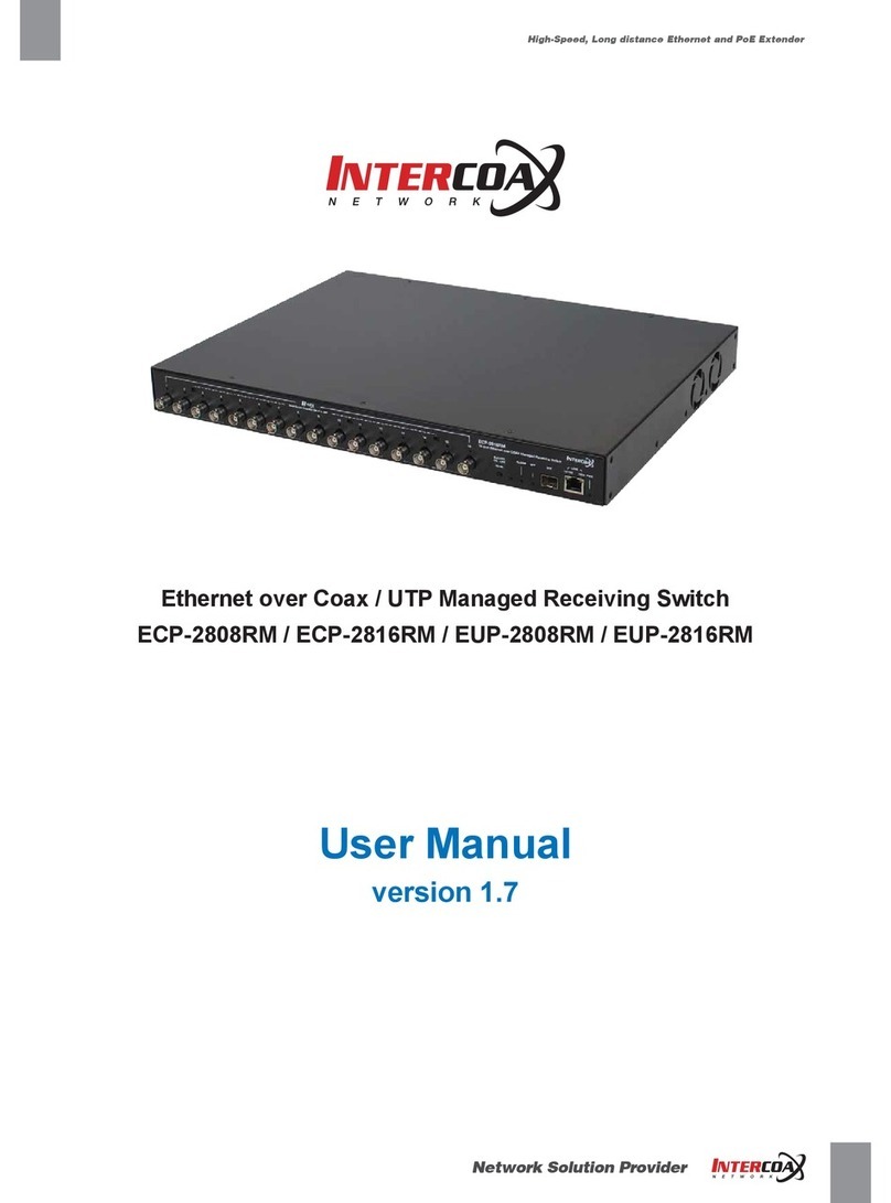
Intercoax ECP-2808RM User manual

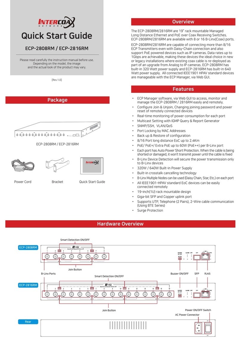
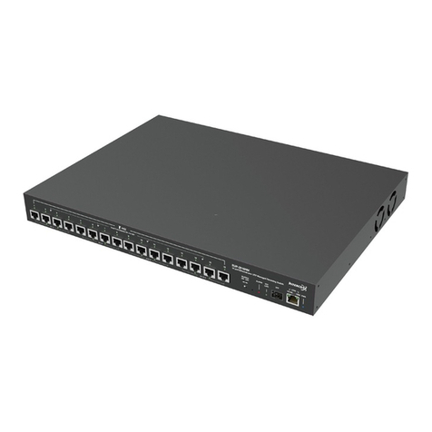
Ethernet over Coax / UTP Managed Receiving Switch
ECP-2808RM / ECP-2816RM / EUP-2808RM / EUP-2816RM
User Manual
Version 3.0

Contents
Precaution and Safety Guidelines .................................................................. 4
1. Product Overview ........................................................................................ 5
1.1. Introduction....................................................................................................................5
1.2. Features..........................................................................................................................5
1.3. Package Contents ........................................................................................................5
2. Hardware Installation .................................................................................. 6
2.1. Front Panel.....................................................................................................................6
2.2. Rear Panel ......................................................................................................................7
2.3. LED Indication ...............................................................................................................8
2.4. Conguration Instruction .............................................................................................9
2.4.1. Prepare devices and materials ..................................................................................9
2.4.2. Hardware Installation.................................................................................................9
2.4.2.1. Rackmount Bracket Installation Guide
2.4.2.2. Rack Mount Instructions
2.6. Typical Installation ......................................................................................................12
3. Product Specications.............................................................................. 13
3.1. Technical Specications.............................................................................................13
3.2. Regulatory Certications ...........................................................................................13
4. Management Software Conguration...................................................... 14
4.1. Overview.......................................................................................................................14
4.2. System Requirements.................................................................................................14
4.3. Installing ECP Manager...............................................................................................15
4.4. Setting up ECP Manager.............................................................................................18
4.4.1. Setting up Groups and ECP Units...........................................................................18
4.4.2. Admin Window.........................................................................................................21

4.5. Conguring and Monitoring RM Units in ECP Manager .........................................22
4.5.1. Changing the IP Address.........................................................................................22
4.5.2. Join & Node Control ................................................................................................24
4.5.3. Node Monitor ...........................................................................................................24
4.5.4. Power ......................................................................................................................25
4.5.5. Trac.......................................................................................................................26
4.5.6. Multicast ..................................................................................................................26
4.5.7. Settings....................................................................................................................27
4.6. SNMP ...........................................................................................................................30
4.7. Web GUI .......................................................................................................................33
4.8. SSH ..............................................................................................................................34
5. Warranty Policy.......................................................................................... 40
6. Regulatory and Certicates...................................................................... 40
7. Customer supports.................................................................................... 40

4
Precaution and Safety Guidelines
• Please install the device following the installation guide.
• Read all warnings.
• Warning: Do not touch the device and cable with wet hands.
• Warning: Clean this device only with a dry cloth.
• Warning: Please do not put the device on anything electrically conductive (screwdrivers, coins, iron, etc.)
and do not put them around water.
• Warning: Do not install near any heat sources such as radiators, stoves
or other devices that produce heat.
• Warning: Do not use for other purposes.
• Warning: Do not put the signal lines (Coax, UTP) in the same conduit as high voltage wiring
• Do not apply any sticker or paint onto the device.
• Indoor use only.
• Please use only attachments or accessories specied by the manufacturer.
• Unplug the device during a lightning storm or when the device is not used for a long time.
• Do not connect analog cameras to the BNC connectors (B-Linx Port) on this device (ECP Series only).
• Do not connect any IP devices to the RJ45 connectors (T-Linx Port) on this device (EUP Series only).
• When the unit is not working properly, please contact your supplier or customer service.
• Please do not disassemble the unit by yourself.
• If this device emits smoke, abnormal noise, or a strange odor, please turn o
the power switch, unplug the AC power cord immediately, and contact your supplier or customer service.
The lightning ash with arrowhead symbol within an equilateral triangle, is intended
to alert the user to the presence of uninsulated “dangerous voltage” within
the product’s enclosure that may be of sucient magnitude to constitute a risk
of electric shock to persons.
The exclamation point within an equilateral triangle is intended to alert the user
to the presence of important operating and maintenance (servicing) instructions
in the literature accompanying the product.

Product Overview — 5
1. Product Overview
1.1. Introduction
The Intercoax ECP/EUP-2808RM/2816RM Series are 19” rack mountable managed Long Distance Ethernet and
PoE over Coax/UTP Receiving Switches.
ECP/EUP-2808RM/2816RM series are capable of connecting 8/16 ECP Transmitters and also support PoE
powered devices such as IP cameras.
Data rates up to 1Gbps are achievable, making these devices the ideal choice in new or legacy installations where
existing Coax/UTP cable is re-deployed as part of an upgrade from analog to IP cameras.
ECP/EUP-2808RM series have built-in 320 Watt power supply and ECP/EUP-2816RM series have built-in 640 Watt
power supply (*Dual power supply of 320W + 320W for power sharing and redundancy)
PoE up to 60W per port is available.
Our browser based GUI manages all connected IEEE1901-HPAV standard devices.
Furthermore, our “Intercoax ECP Manager” software allows managing multiple of the ECP/EUP-2808RM/2816RM
series, remotely from the central management oce.
1.2. Features
• Ethernet & PoE transmission over Coax / UTP cable
• Complies to IEEE1901-HPAV standard
• Extended transmission distance up to 2,400m
• PoE up to 60W (802.3bt) per B-Linx port & T-Linx port
• Management software, “Intercoax ECP Manager", supported
• Remote power on/o and reset of each port
• Real-time monitoring of power consumption for each port
• Multicast Setting with IGMP Query & Report Generator
• SNMP ready
• VLAN ready
• MAC Address Locking on each port for extra secure network connectivity
• Alarm LED & buzzer and notication on ECP Manager
• Scheduled event reporting and alert reporting to designative users
• Back up & Restore of conguration
• Auto Power Short Protection
• B-Linx & T-Linx Smart Device Detection for safe power transmission
• 320W (8 port) / 640W (16 port) Built-in Power Supply
• Built-in crosstalk cancelling technology
• Gigabit SFP and Copper uplink port
• 19-inch(1U) rack mountable design
1.3. Package Contents
ECP-2816RM
(ECP-2808RM / EUP-2808RM / EUP-2816RM)
Bracket Quick Installation
Guide
AC Power cord

Hardware Installation — 6
2. Hardware Installation
2.1. Front Panel
2
4
3
56 7 8
56 7 8
56 7 8
1
2
15 6
3
3
3
4
4
4
7 8
[EUP-2816RM]
[ECP-2816RM]
[EUP-2808RM]
[ECP-2808RM]
No. Description
1
B-Linx Ports (1~8 / 1~16) :
Connect Intercoax ECP Transmitters or IEEE1901-HPAV standard devices by coaxial cable with BNC male
connector.
2
T-Linx Ports (1~8 / 1~16) :
Connect Intercoax ECP Transmitters or IEEE1901-HPAV standard devices by UTP cable with RJ45 male
connector.
3
Smart B-Linx / T-Linx Detection On O :
B–Linx / T-Linx Detection mode On/O switch
- Detection Mode ON: Detects B-Linx & T-Linx devices before supplying power over Coax.
- Detection mode OFF: By-pass detection, classication and power management checks.
[Caution]
Do not connect analog cameras or network devices on BNC or RJ-45 port directly if Smart
B-Linx / T-Linx detection switch is OFF, it may cause serious damage to the device connected.

Hardware Installation — 7
No. Description
5Buzzer On O :
Move the switch left or right to set the buzzer sound on or o.
6
Factory Reset :
The hidden factory reset button.
Press and hold for 10 seconds the reset button to restore to its original IP settings (192.168.4.17/24)
7SFP :
Connect an SFP module for uplink data (1000Base-SX and 1000Base-LX slot).
8Link :
Connect an RJ45 Ethernet cable for uplink data (10/100/1000 Base-T).
2.2. Rear Panel
2 1
No. Description
1Power ON/OFF Switch
2Power Connector
The connector is for 100~240V AC power input 50Hz/60Hz

Hardware Installation — 8
2.3. LED Indication
2
213 4 6
5
3 4 6
5
2
[EUP-2816RM]
[ECP-2816RM]
[EUP-2808RM]
[ECP-2808RM]
213 4 6
5
3 4 6
5
No. LED
Indication On O Blinking
1B-Linx/T-Linx
(1~8 / 1~16)
• ECP/EUP Transmitter is
connected
• Power over coax / UTP
working properly
• No device connected
on B-Linx / T-Linx port
• Short circuit or over current
protection is working
2
Join
(1~4 / 5~8,
9~12, 13~16)
•• Unjoined ECP device is
connected
• ECP/EUP transmitter linked
properly
• Transmitting Data Via
Coax / UTP
3 Alarm • System boot-up
• Alarm is detected • Device in normal operation • Factory reset is progressing
4 SFP Link • Transmitting Data
• SFP Link is down
• No device connected on
SFP port
•
5 LINK • • Uplink (Copper) is down
• Transmitting Data
Green: 10/100 Mbps
Amber: 1000 Mbps
6 PWR • Power ON • Power OFF •

Hardware Installation — 9
2.4. Conguration Instruction
2.4.1. Prepare devices and materials
• Ethernet over Coax /UTP Receiving Switch (ECP-2808RM, EUP-2808RM, ECP-2816RM, EUP-2816RM)
• ECP-Transmitters (ECP-2601, ECP-2701, etc.)
• EUP-Transmitters (EUP-2601T & or ECP Transmitters with BTE-02)
• RJ-45 patch cord
• Coax cables (ECP) or 4 pairs Cat5 or up UTP cables (EUP)
• Network Switch and PC (OS: Window 7 or later)
2.4.2. Hardware Installation
1. Use Coax (ECP) or UTP cables (EUP) to connect the receiving switch and the ECP/EUP-Transmitters.

Hardware Installation — 10
2. Connect ECP-Transmitters to the IP end device (e.g. IP Camera, IP Access Control Unit, VoIP phone, etc.)
(If you want the device to be powered by PoE, Please set the PoE Switch to ‘ON’ on the ECP Transmitter).
Connect the receiving switch to your Network Switch or your PC using the RJ45 Patch cord.
3. Alternatively, use optical SFP Transceiver modules and a ber cable to connect to the SFP uplink port of the
receiving switch to an optical SFP port of your Network Switch. This can be used as standalone connection or
redundant port.
4. Apply power to the receiving switch.

Hardware Installation — 11
2.4.2.1. Rackmount Bracket Installation Guide
1. Remove the 3 factory installed screws from both sides of the receiving switch and keep these screws as they
will be used to attach the new rack mount brackets. (See Picture 1 & 2)
Picture 1 Picture 2
2. Using these screws, attach the supplied rackmount bracket to the managed switch (Carefully check LEFT and
RIGHT side brackets, see pictures 3 & 4).
Picture 3 Picture 4
2.4.2.2. Rack Mount Instructions
1. Elevated Operating Ambient - If installed in a closed or multi-unit rack assembly, the operating ambient
temperature of the rack environment may be greater than room ambient.
Therefore, consideration should be given to installing the equipment in an environment compatible with the
maximum ambient temperature (Tma) specied by the manufacturer.
2. Reduced Air Flow - Installation of the equipment in a rack should be such that the amount of airow required
for safe operation of the equipment is not compromised.
3. Mechanical Loading - Mounting of the equipment in the rack should be such that a hazardous condition is not
achieved due to uneven mechanical loading.
4. Circuit Overloading - Consideration should be given to the connection of the equipment to the supply circuit
and the eect that overloading of the circuits might have on overcurrent protection and supply wiring.

Hardware Installation — 12
2.5. Typical Installation
• The ECP/EUP-2808/2816RM Series deliver high bandwidth and power over coax/UTP cable.
All ECP/EUP single port units or ECP/EUP transmitter series can be used as remote transmitters, typically
located at the IP camera.
• Application Examples
ECP-2816RM
EoC
PoC
PoE Camera
ECP-2704T
Coax
PoE
Data
AC 100~240V
AC 100~240V
NVR Network Switch
ECP-2701
Coax
Coax
Coax
ECP-2701
ECP-2701
ECP-2701
PoE Camera
PoE
Data
EUP-2816RM
EoC
PoC
ECP-2704T
Cat.5e or Better
ECP-2701
BTE-02
BTE-02
Cat.5e or Better
EUP-2601T
Cat.5e or Better
EUP-8401T
Cat.5e or Better
NVR Network Switch
48V~56VDC
Ethernet
PoE-PWR
Data-Link
Join-Link
PowerON
Join
PoE
OFF-ON
EUP-8401
EthernetoverCoaxTransceiver

Product Specifications — 13
3. Product Specications
3.1. Technical Specications
Model ECP-2808RM EUP-2808RM ECP-2816RM EUP-2816RM
Interface
Coax
8 * 75Ω BNC
(Female) - Ethernet
over Coax (B-Linx)
16 * 75Ω BNC
(Female) - Ethernet
over Coax (B-Linx)
UTP
8 * 100Ω RJ45
(Female) - Ethernet
over Twisted Pairs
(T-LinX)
16 * 100Ω RJ45
(Female) - Ethernet
over Twisted Pairs
(T-LinX)
Up-Link 1 x RJ45 - 10/100/1,000 Base-T with Auto MDIX, 1 x SFP - 1,000 Base-SX/LX/T
B-Linx / T-Linx Transmission Rate
(Ethernet over Coax/UTP) UP to 560Mbps Full Duplex UP to 1Gbps Full Duplex
B-Linx / T-Linx Communication Standard IEEE1901-HPAV
B-Linx / T-Linx Communication Modulation OFDM
ECP Manager Connectivity Available
IGMP IGMP (V1/V2/V3) Snooping, IGMP Query & Report Generator
Data Transmission
Distance
Coax Up to 2,400m (RG6)
UTP Up to 1,200m (Cat.5e)
Power Transmission
Distance
Coax Up to 1,200m (RG6 / 7W)
UTP Up to 1,500m (Cat.5e / 7W)
LED Indication
Power Blue
RJ45 Up-Link Green (10/100-Link) / Yellow (1,000-Link)
SFP Up-Link Green (1,000-Link)
Channel Green
Join Green
Alarm Red
Buzzer Event Buzzer / Mute
Encryption 128-bit AES
Power
AC Input AC100V~240V (50Hz/60Hz), 320W
DC output per Port Max DC 57V, 1.07A (60W per port for PoE support)
Port Short
Protection Auto Detection & Protection
Smart B-Linx / T-Linx Device Detection Detection On / O
Mechanical Dimension 441.5(L) x 349(W) x
44(H) mm
441.5(L) x 340(W)
x 44(H) mm
441.5(L) x 349(W)
x 44(H) mm
441.5(L) x 340(W)
x 44(H) mm
Weight 4,650g 4,600g 5,090g 5,030g
Environment
Operating Temp 0C ~ +60C
Storage Temp -30C ~ +80C
Relative Humidity 10% ~ 80%
Compliance Certication CE (including Railways Standard EN 50121-4), FCC, KC, UL
Surge Protection IEC61000-4-5 4kV(1.2 / 50us), 2kA(8/20us)
3.2. Regulatory Certications

Management Software Configuration — 14
4. Management Software Conguration
4.1. Overview
█ECP MANAGER LITE & ECP MANAGER
• The ECP MANAGER LITE is the browser based GUI. Users can access to management of all
ECP/EUP-2808/16 series and its connected IEEE1901-HPAV standard transmitters.
• The ECP MANAGER software allows managing multiple INTERCOAX Managed Receivers remotely from the
central management oce. With the ECP MANAGER software, users can access to all connected
IEEE1901-HPAV standard transmitters.
• Various additional features are available with the ECP Manager and ECP Manager Lite as below:
- Remote monitoring for ECP/EUP devices & End or remote (usually Tx models) device connection
- Remote transceiver Joining (Network Grouping)
- IP addressing for managed EoC Switch
- System reboot
- Power reset by each port
- Real time Monitoring for power consumption by each port
- Real time Monitoring for total power consumption
- Port locking for extra secured network connectivity
- Multicast setting with IGMP Query Generation
- Scheduled event reporting and alert reporting to designative users
- SNMP Setting
- VLAN Setting
- QoS Setting
- Conguration backup & Restore
4.2. System Requirements
• Recommended Operating System for ECP Manager : Windows 7 or Higher version
• Internet connectivity : During initial installation for ECP manager, an internet connection is required.

Management Software Configuration — 15
4.3. Installing ECP Manager
To download the ECP Manager and its prerequisites, please visit www.intercoax-emea.com in your browser:
In the top navigation bar, select 'Support':
In the lter, select 'Software':
Click on the download button next to 'ECPManager_v3.0.zip' to download the le:
Save the .zip le where you want and unpack it with your preferred unpacking software (WinRAR, 7Zip, etc.)
Go into the unpacked folder and install the prerequisites.
If you use Windows 7 or lower, you need to run the ‘dotNetFx45_Full_stup’ installer for the .NET 4.5 Framework.
When using Windows 8 or higher, this step is not necessary.
Follow the instructions in the installer to complete this setup.

Management Software Configuration — 16
Next, you need to install the second prerequisite, the SSCE Runtime software.
There are two options, 32-bit (x86) and 64-bit, depending on your Operating System.
When in doubt, start with running the 64-bit installer:
If an error shows up explaining your Operating System does not support x64 software, use the other installer:
Follow the instructions in the installer to nish the installation.
After having installed the necessary prerequisites, we can start installing ECP Manager itself.
Start by going into the ‘ECPManager folder’:
Next, run the installer software for ECP Manager:
Select the ‘Install’ option:

Management Software Configuration — 17
After the installation has nished, ECP Manager will start automatically.
When never having installed ECP Manager before, ECP Manager will create a new folder and database:
Continue at all the message boxes:
ECP Manager will open up with the login screen showing:
If a Windows Security Alert is displayed, tick both boxes and select ‘Allow Access’:
You are now ready to start using ECP Manager.

Management Software Configuration — 18
4.4. Setting up ECP Manager
4.4.1. Setting up Groups and ECP units
Start ECP Manager, if it is not running already.
It will show the login screen. Use the credentials ‘admin’ and password ‘admin’ to log in:
In the left navigation panel, select ‘ECP Cong’:
In the ‘Group Conguration’ tab, you can set up groups of RM units to monitor.
These can be individually enabled or disabled to monitor dierent groups of RM units in separate buildings/
networks.
Make a new Group by giving it a name and giving up the location, followed by clicking the ‘Add’ button:
You will see the newly created Group in the list below:

Management Software Configuration — 19
Next, select the ‘ECP Conguration’ tab to add RM units to the Group we made just now.
Fill out the information to add the RM you would like to manage and monitor:
Select the Group we just made, the model you have, and give up the IP of the RM device.
The standard IP Address of all RM units is 192.168.4.17.
Give up a desired Location and set the monitoring settings.
The Monitoring Settings in this screen capture should suce for most situations.
When ready, click ‘Add’ to create the ECP unit. You will see it in the list:
We can now go the ‘General’ page to see the newly set up RM unit:

Management Software Configuration — 20
Most likely, the unit we added will not be detected yet:
When the Red ‘Check’ shows, this means your ECP Manager cannot connect to any RM units in your enabled
Groups.
When an Orange ‘Check’ shows, ECP Manager cannot connect to some but not all RM units in your enabled
Groups.
If a Green ‘OK’ is shown, ECP Manager can connect to all RM units of your enabled Groups.
The next step is to connect your PC/Laptop, running ECP Manager, with the RM unit we just set up in ECP
Manager.
Connect your PC/Laptop Ethernet port with the Ethernet Uplink Port of the RM, using an RJ45 UTP Cable.
Set your ethernet interface settings to be in the same network as the RM unit on 192.168.4.17:
Power up the RM unit if it isn’t already, and wait for it to be completely booted up. This will be accompanied by a
short beeping sound.
You should now be able to see the RM unit being connected in ECP Manager:
Other manuals for ECP-2808RM
3
This manual suits for next models
3
Table of contents
Other Intercoax Switch manuals
Intercoax
Intercoax ECP-2808RM User manual
Intercoax
Intercoax HPS-1008 User manual
Intercoax
Intercoax 2816RM-ECP User manual

Intercoax
Intercoax ECP-2808RM User manual
Intercoax
Intercoax FLX-1008 User manual
Intercoax
Intercoax ECP-101T User manual
Intercoax
Intercoax EUP-2816RM User manual
Intercoax
Intercoax ECP-2808RM User manual
Intercoax
Intercoax HPS-01 User manual

Intercoax
Intercoax HPS-01 User manual


