AVGear AVG-SC121D-TN User manual

AVG-SC121D-T
Features
12 video Inputs: 4 HDMI, 4 VGA, 1
YPbPr, 2 C-video & 1 S-video
2 MIC inputs with level control and
mixer function
Upscale to HDBaseT, HDMI & VGA
simultaneously up to 1080P.
HDBaseT output to be paired with
receiver TPHD402PR for 60M
transmission distance
Built-in 2x20Watt@4Ω digital amplifier
(or 2x10Watt@8Ω)
Output resolution is selectable
Output display H/V size: adjustable to
eliminate any overscale error
Output display H/V position moveable.
MIC volume and line volume adjustable
Extensive OSD function with full control
HDMI1.3 and HDCP compliant.
Firmware updatable via USB
Output freeze function
Power PoC receiver (e.g. TPHD402PR)
with PoC function
Front panel lockout feature
Controllable via receiver TPHD402PR
at display end.
Controllable via front panel, IR, RS232
& TCP/IP.
The AVG-SC121D-T is a full HD scaler switcher
with 12 video, 6 audio & 2 MIC inputs. It scales
& switches HDMI, VGA, YPbPr, C-Video & S-
video to HDBaseT, HDMI & VGA
simultaneously, and audio to a 2x20W amplifier.
It’s controllable via the front panel, IR, RS232 &
TCP/IP.

AVG-SC121D-T
PLEASE READ THIS PRODUCT MANUAL CAREFULLY
BEFORE USING THIS PRODUCT.
This manual is only for operational instruction only,
and not to be used for maintenance. The functions
described in this version are current as at March 2015.
Any changes of functions and operational parameters
will be updated in future manual versions. Please refer
to your dealer for the latest product details.
Version 1.0 1/3/15
AVG-SC121D-T
SAFETY OPERATION GUIDE
In order to guarantee the reliable operation of the equipment and safety of the
user, please abide by the following procedures in installation, use and
maintenance:
1. The system must be earthed properly. Please do not use two blade plugs
and ensure the alternating power supply ranges from 100v to 240v and from
50Hz to 60Hz.
2. Do not install the switcher in an environment where it will be exposed to
extreme hot or cold temperatures.
3. This unit will generate heat during operation, please ensure that you allow
adequate ventilation to ensure reliable operation.
4. Please disconnect the unit from mains power if it will be left unused for a
long time.
5. Please DO NOT try to open the casing of the equipment, DO NOT attempt to
repair the unit. Opening the unit will void the warranty. There are high
voltage components in the unit and attempting to repair the unit could result
in serious injury.
6. Do not allow the unit to come into contact with any liquid as that could result
in personal injury and product failure.

AVG-SC121D-T
TABLE OF CONTENTS
Introduction ..............................................................................................................1
Introduction to AVG-SC121D-T....................................................................1.1
Features .......................................................................................................1.2
What’s in the Box..........................................................................................1.3
Panel Description.....................................................................................................2
Front Panel...................................................................................................2.1
Rear Panel....................................................................................................2.2
System Connection..................................................................................................3
Usage Precautions.......................................................................................3.1
System Diagram...........................................................................................3.2
Connection Procedures................................................................................3.3
POC Support................................................................................................3.4
Complimentary Products ..............................................................................3.5
Operations ................................................................................................................4
Operations of the IR Remote........................................................................4.1
OSD Operations...........................................................................................4.2
Picture Setting ................................................................................4.2.1
Audio Setting ..................................................................................4.2.2
System Setting................................................................................4.2.3
Firmware Update..........................................................................................4.3
RS232 Control..............................................................................................4.4
Installation/Removal of RS232 Control Software............................4.4.1
Basic Settings.................................................................................4.4.2
RS232 Commands .........................................................................4.4.3
TCP/IP Control .............................................................................................4.5
IP Configuration..............................................................................4.5.1
Connection Introduction..................................................................4.5.2
Specifications...........................................................................................................5
Specifications of AVG-SC121D-T.................................................................5.1
Specifications of Video/Audio Input/Output ..................................................5.2
C-Video and S-Video Input.............................................................5.2.1
YPbPr Input ....................................................................................5.2.2
VGA Input.......................................................................................5.2.3
HDMI Input......................................................................................5.2.4
Audio Input/Output........................................................................................5.3
Panel Drawing ..........................................................................................................6
Troubleshooting & Maintenance.............................................................................7
After-sales Service...................................................................................................8

AVG-SC121D-T
1. Introduction
1.1. Introduction to AVG-SC121D-T
The AVG-SC121D-T is a full HD scaler switcher with 12 video, 6 audio & 2 MIC
inputs. It scales & switches any video signal HDMI, VGA, YPbPr, C-Video & S-video
to HDBaseT, HDMI & VGA simultaneously, and any audio to 2x20W amplifier. It’s
controllable via the front panel, IR, RS232 & optional TCP/IP.
It’s a versatile scaler for use in education institutions, meeting rooms, conference
rooms, etc.
1.2. Features
12 video Inputs: 4 HDMI, 4 VGA, 1 YPbPr, 2 C-video & 1 S-video.
2 MIC inputs with level control and mixer function.
Upscale to outputs HDBaseT, HDMI & VGA simultaneously up to 1080P.
HDBaseT output to be paired with receiver TPHD402PR for 60M transmission.
Built-in 2x20Watt@4Ω digital amplifier (or 2x10Watt@8Ω).
Output resolution selectable to assure preferred output.
Output display H/V size: adjustable to correct any overscale error.
Output display H/V position moveable.
MIC volume and line volume adjustable.
Video parameter setting and preset.
Extensive OSD function with full control.
HDMI1.3 and HDCP compliant.
Firmware updatable via USB.
Output freeze function.
Power PoC receiver (e.g. TPHD402PR) with PoC function
Front panel lockout.
Controllable via receiver TPHD402PR at display end.
Controllable via front panel, IR, RS232 & TCP/IP.

AVG-SC121D-T
1.3. What’s in the Box
1 x AVG-SC121D-T
1 x HDBT Receiver (not included in package contends of SC121D, SC121D-N)
2 x Mounting Ears (for HDBT Receiver)
4 x Screws
3 x Captive Screw Connectors
1 x RS232 cable
4 x Plastic cushions
1 x IR remote (Cell battery is not included)
1 x Power Cord
1 x User Manual
Note: Please confirm if the product and the accessories are all included, if not,
please contact with the dealers.
AVG-SC121D-T
2. Panel Description
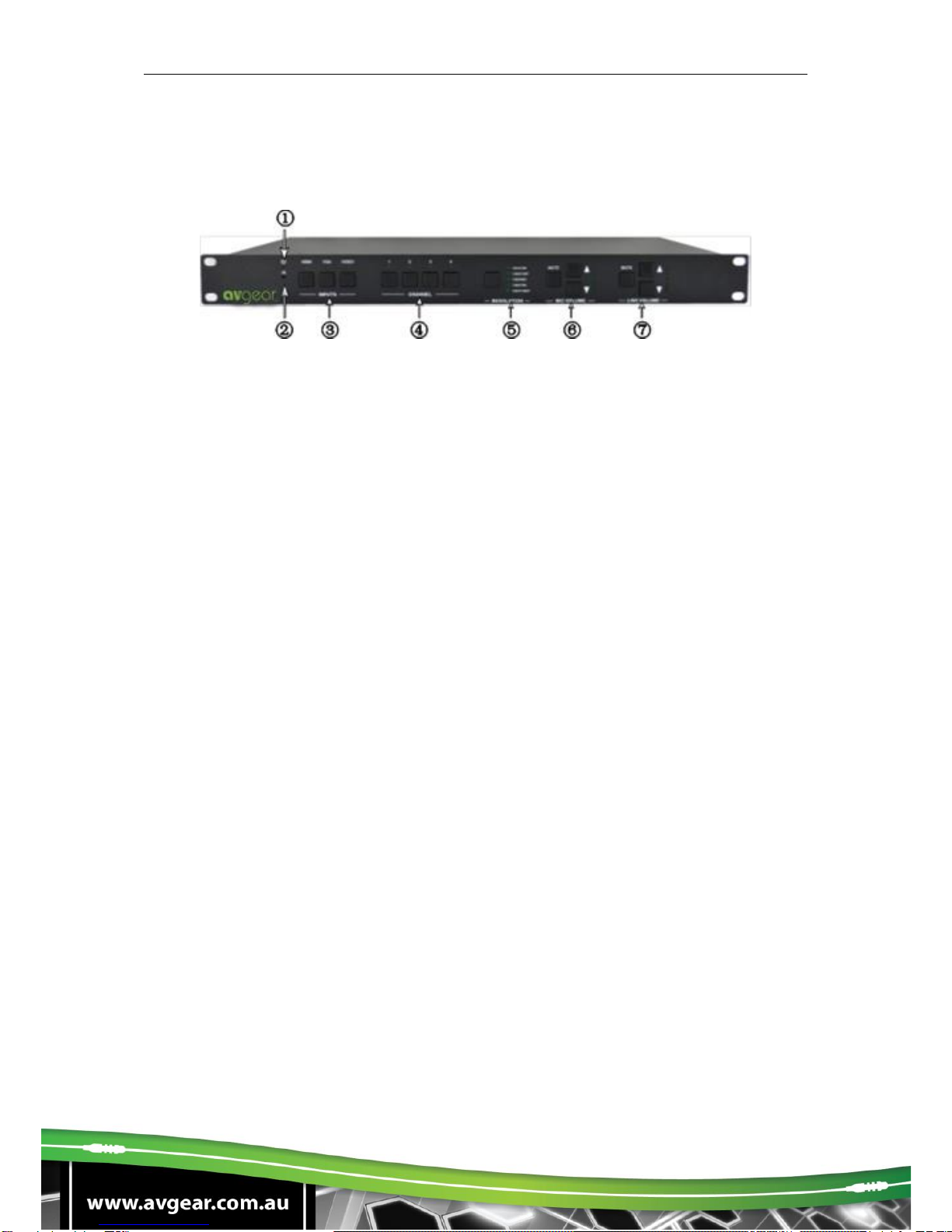
2.1. Front Panel
①Power indicating LED. It will illuminate red when the unit is connected with
power.
②IR sensor, receive signals sent from of IR remote.
③Video source selection buttons. You can select video/audio sources by pressing
these buttons. And VIDEO source includes three different signals: YPbPr, C-
Video and S-Video.
④Signal channel selection buttons, 4 in total, correspond to the 4 input sources
separately.
⑤Resolution selection buttons. These including 1024×768, 1280x720p, 1280×800,
1360×768, 1920×1080p.
⑥MIC volume control buttons. “MUTE” for mute MIC volume, “△”for MIC volume
up, “▽”for MIC volume down, loop controlling.
⑦Line volume control buttons. “MUTE” for muting line volume, “△”for line volume
up, “▽”for line volume down.
Note: Pictures shown in this manual are for reference only, different model and
specifications are subject to real product.

AVG-SC121D-T
2.2. Rear Panel
①Two RCA connectors for stereo audio output;
One VGA output;
One HDMI output with audio embedded;
One HDBT port (selectable) for HDMI extending (works with TPHD402PR),
supporting PoC.
②Four VGA connectors for VGA inputs.
③Four HDMI connectors for HDMI inputs.
④Four 3.5mm audio connectors for VGA audio inputs.
⑤One Component video input: Y/Pb/Pr, two composite video inputs: C-Video, one
Separate video input: S-Video, two pairs L/R for analog audio input.
⑥One RS232 port for control, one USB port for firmware update.
⑦Two MIC connectors: MIC with pre-amplification, LINE for audio direct input.
One TCP/IP port (optional): for network controlling.
⑧Amplifier with 2x10W@8Ω output.
⑨Connector for POWER.
⑩Grounding protection.
Note:
Pictures shown in this manual are for reference only
The TCP/IP port and HDBT port are selectable. When there is a TCP/IP port, the
switcher may be named as SC121D-N. When there is an HDBT port, the switcher
may be named as SC121D-T.
For example, the name “AVG-SC121D-T” suggests that the switcher supports
both the ports. While “SC121D” suggests that the switcher has neither a TCP/IP
port nor a HDBT port.

AVG-SC121D-T
3. System Connection
3.1. Usage Precautions
1. The system should be installed in a clean environment and has proper
temperature and humidity.
2. All of the power switches, plugs, sockets and power cords should be insulated
and safe.
3. All devices should be connected before power on.
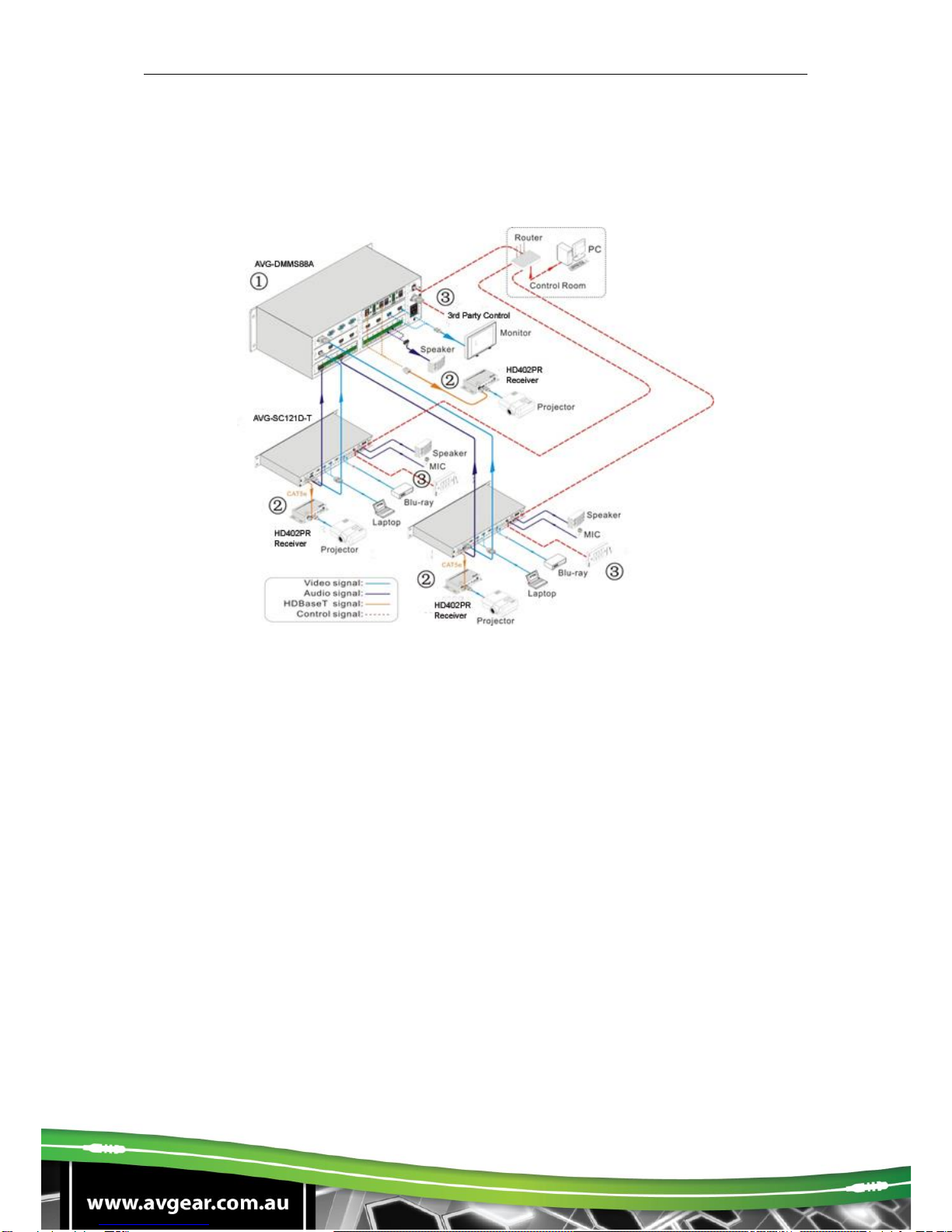
3.2. System Diagram
3.3. Connection Procedures
Step 1. Connect source devices (e.g. PC, DVD) to video input ports with
corresponding cables. For example, connect VGA INPUTS ports and the
VGA ports of source devices via VGA cable.
Step 2. Connect the corresponding audio source to the corresponding AUDIO
INPUT port of AVG-SC121D-T with audio cable separately. C-VIDEO1
shares the same audio input port with S-VIDEO3; YPbPr shares the same
audio input port with C-VIDEO4, you can select either side as audio input
port.
Step 3. Connect a microphone to the MIC input port; plug an audio source device
or a wireless microphone to the LINE port.

AVG-SC121D-T
Step 4. Connect a control device (e.g. a PC) to the TCP/IP ports or RS232 sockets
of AVG-SC121D-T. Send commands to control AVG-SC121D-T via control
software.
Step 5. Connect the HDMI HDBT port of AVG-SC121D-T with TPHD402PR to
extend the signal.
Step 6. Connect display devices to video output ports; connect
earphones/amplifiers to audio output ports. (Abiding by the color instruction
on output sockets)
Step 7. Connect the output ports of amplifiers to stereo equipment.
Step 8. Plug the power cable of AVG-SC121D-T to an AC100V~240V power
supply, TPHD402PR is able to get energized with PoC solution.
3.4. PoC Support
The HDBT port supports PoC, which allows AVG-SC121D-T and TPHD402PR to
share the same power supply and eliminates the need for extra power supply at the
remote nodes.
Connect AVG-SC121D-T with TPHD402PR via a CAT5e/6 cable, then plug the
power cable of AVG-SC121D-T to an AC100V~240V power supply, TPHD402PR
can be energized synchronously with PoC solution, see the picture below:
Note: To activate the PoC solution, all related parts (including the devices to share
the same power supply and connecting cable) should support PoC.
AVG-SC121D-T
3.5. Complimentary Products
AVG-SC121D-T usually works with other devices to deliver multiple video & audio
sources. Here are the most common ancillary products.
Description:
1. DMMS88A
Various I/O cards, includes HDMI, HDBaseT, SD/HD/3G-SDI, DVI and VGA
cards (Compatible with YUV, YC & CVBS.) to configure any matrix.
Support HDMI1.4a, support 3D.
Integrated HDBaseT technology.
Controllable via button, RS232 & optional TCP/IP, also compatible with 3rd
parties control.
LCD display.
2. HD300 (HDMI twisted pair Receiver with PoC)
60m transmission distance in max over single CAT5e/CAT6 cable.
Supports 1080P@60Hz,48b/pixels,3D & 4Kx2K.
Supports PoC & CEC.
Bi-directional and simultaneous RS232 & IR control.
AVG-SC121D-T
4. Operations
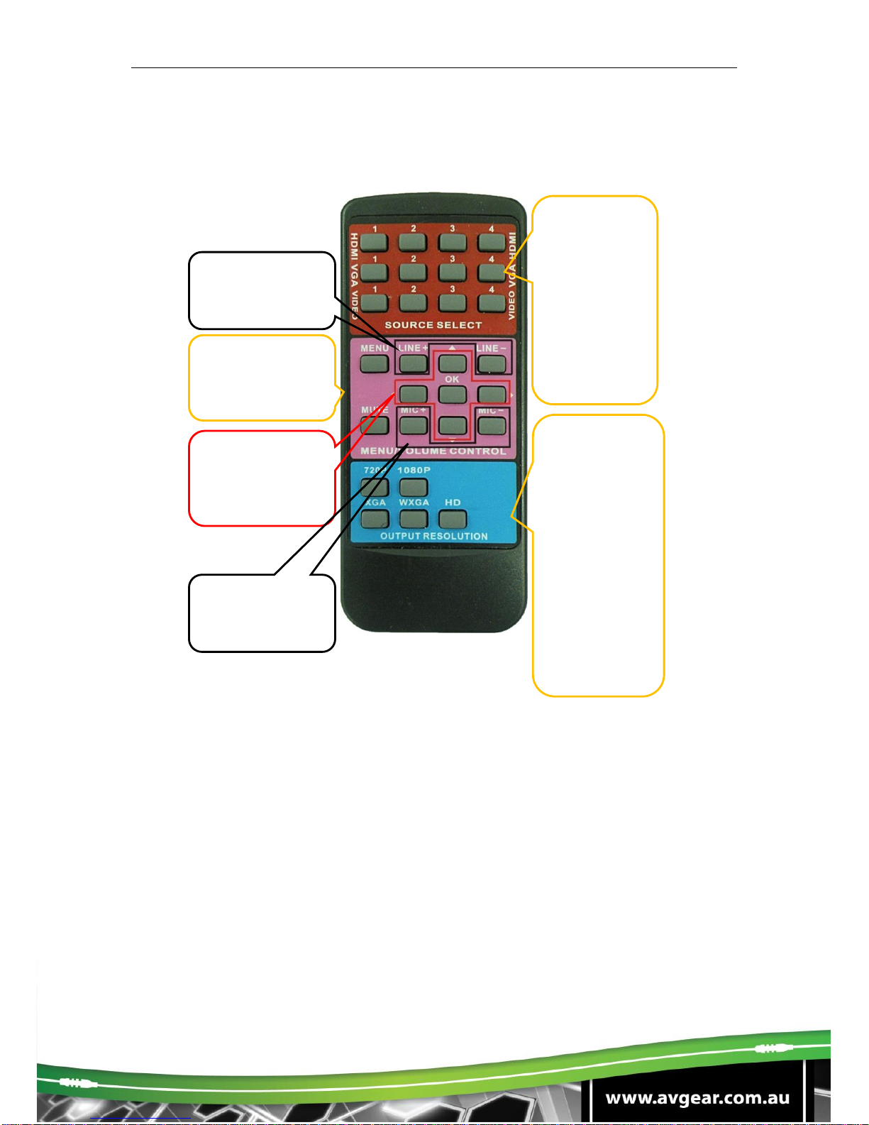
4.1. Operations of the IR Remote
4.2. OSD Operations
AVG-SC121D-T provides an OSD operation menu, with various functions and
languages.
The operation introduction is shown as follows.
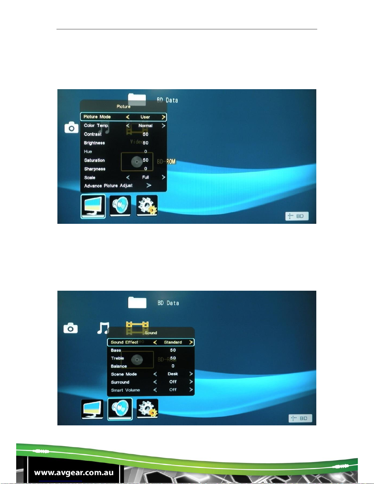
4.2.1. Picture Setting
The first icon from left of the OSD menu is to set the picture parameter. It includes
picture mode, color temperature, contrast, brightness, hue, saturation, sharpness,
scale, and Advance picture adjust.
Some parameters are available depending on different inputs.
Source select
area, 12
channels for
inputs,
including:
4 HDMI
4 VGA
2 C-VIDEO
1 S-Video
1 YPbPr
Direction and OK
buttons area, these
buttons are
available only in
MENU mode.
Menu/ Volume
control area, MUTE
for line and MIC
audio mute.
Line volume control
area, can work
when not in MENU
mode.
MIC volume control
area, can work
when not in MENU
mode.
Output
resolution select
area, five
different
resolutions can
be selected,
including:
720P:
1280x720
1080P:
1920x1080
XGA: 1024x768
WXGA:
1280x800
HD: 1360x768
AVG-SC121D-T
In the item Advanced Picture Adjust, users can set Digital Noise Reduction, dynamic
color, skin tone and Adaptive Luma adjustment function.
Please check the picture below:
4.2.2. Audio Setting
The Second icon from left of the OSD menu is to set the audio/sound parameter. It
includes the sound effect preset, bass, treble, balance, scene mode, surround and
smart volume setting. Some parameters are available depending on different inputs.
Please check the picture below:
AVG-SC121D-T
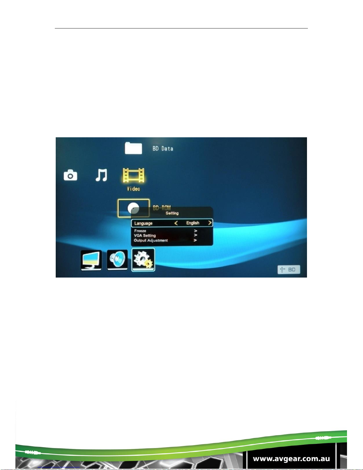
4.2.3. System Setting
The Third icon from left of the OSD menu is the system setting, which includes OSD
language setting, listen, freeze, VGA setting, output adjustment etc.
Listen: Audio output only. To resume video output, please press button “MENU”.
VGA setting: Adjust the H/V signal of VGA input, includes auto adjustment.
Output adjustment: Adjust H/V size and H/V position of the output. This function
is available only with HDMI and VGA inputs.
4.3. Firmware Update
AVG-SC121D-T supports firmware field-updating by USB flash disk. The operation
procedures are:
1. Copy the file “MT23ATV.bin” to a USB flash disk. (The “MT23ATV.bin” file is
provided/ authorized by AV GEAR engineering department)
2. Plug the USB flash disk to the USB port on AVG-SC121D-T.
3. Pressing the button “HDMI” on the front panel for 6 seconds or sending RS232
command 0698% for updating, then press the button “OK” on the remote or send
RS232 command 0609% to confirm update. AVG-SC121D-T will capture the new
firmware from USB flash disk.
4. After finishing update, reboot and send the command “0617%” to reset to factory
settings.
5. After reset, reboot again.

AVG-SC121D-T
Notice: The name of the update file must be MT23ATV.bin.
4.4. RS232 Control
RS232 signals can be transmitted between the AVG-SC121D-T and HD300, this
enables control of the AVG-SC121D-T from a remote location.
Control local device from remote:
Connect the RS232 ports of the AVG-SC121D-T and HD300, and connect a control
device (e.g. a PC) to TPHD402PR, then it’s able to send corresponding commands
to control the AVG-SC121D-T from the remote.
4.4.1. Installation/Removal of RS232 Control Software
Installation: Copy the control software file to the computer connected with AVG-
SC121D-T.
Removal: Delete all the control software files in corresponding file path.
4.4.2. Basic Settings
Firstly, connect the AVG-SC121D-T with all input devices and output devices
needed, then connect it with a computer which is installed with RS232 control
software. Double-click the software icon to run this software.
Here we take the software CommWatch.exe as an example. The icon is showed as
below:
AVG-SC121D-T
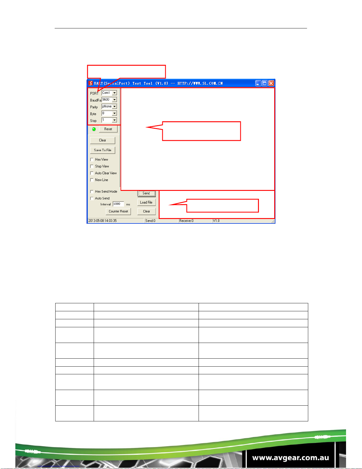
The interface of the control software is showed as below:
Please set the parameters of COM number, bound rate, data bit, stop bit and the
parity bit correctly, and then you are able to send commands in Command Sending
Area.
4.4.3. RS232 Commands
Communication protocol: RS232 Controlling Protocol Command Type: ASCII
Baud rate: 9600 Data bit: 8 Stop bit: 1 Parity bit: none
Command
Function Description
Feedback Example
0600%
MUTE Line
LINE Mute On
0601%
UnMute Line
LINE Mute Off
0602%
Audio turn up, XX ranges from
00 to 99.
LINE Volume: xx (xx=0~99)
0603%
Audio turn down, XX ranges from
00 to 99.
LINE Volume: xx (xx=0~99)
0604%
Lock the front panel button
Panel Locked
0605%
Unlock the front panel button
Panel UnLocked
01XX%
Preset the volume. The XX is
ranging from 00 to 99
Volume: XX
02XX%
Preset the brightness. XX ranges
from 00 to 99.
Brightness: XX
03XX%
Preset the contrast. The XX is
ranging from 00 to 99
Contrast: XX
Parameter
Configuration area
Monitoring area,
indicates whether the
command sent works.
Command Sending
area

AVG-SC121D-T
Command
Function Description
Feedback Example
04XX%
Preset the saturation. The XX is
ranging from 00 to 99
Saturation: XX
05XX%
Preset the sharpness. The XX is
ranging from 00 to 07
Sharpness: XX
0606%
Auto-adjust the input signal(VGA
only)
VGA Adjustment
0607%
Auto-adjust the color
temperature
Color Temp: XX
0608%
ZOOM the image, set the aspect
ratio
Aspect Ratio: XX
0609%
OK, for OSD selection
OK
0610%
Left of OSD
Left
0611%
Right of OSD
Right
0612%
Up of OSD
Up
0613%
Down of OSD
Down
0614%
Set the picture mode
Picture Mode : XX (
0615%
SM Mode
Sound Mode: XX
0616%
MENU of OSD
MENU
0617%
Command to reset to factory
defaults
Factory reset
0618%
Change the resolution to
1360X768 HD
Resolution: HD 1360X768
0626%
Change the resolution to
1024X768 XGA
Resolution: XGA 1024X768
0627%
Change the resolution to
1280X720 720P
Resolution: 720P 1280X720
0628%
Change the resolution to
1280X800 WXGA
Resolution: WXGA 1280X800
0629%
Change the resolution to
1920X1080 1080P
Resolution: 1080P 1920X1080
0630%
Check the volume level
LINE Volume: XX/MIC Volume: XX
0631%
Check the input source
Source: XXXXXX
0632%
Check the output resolution
Resolution: XXXXXXXX
0633%
Check the image mode
Picture Mode : XX
0634%
Check the audio mode
Sound Mode: XX
0635%
Check the image aspec ratio
Aspect Ratio: XX
0636%
Check the brightness
Brightness: XX
0637%
Check the contrast
Contrast: XX
0638%
Check the saturation
Saturation: XX
0639%
Check the sharpness
Sharpness: XX
0640%
Check the color temperature
Color Temp: XX
0644%
OSD CHANNEL display able
OSD Source: Display
0645%
Shield OSD CHANNEL
OSD Channel (Source): No
Display
0646%
Volume Bar display able
Volume Bar: Display
0647%
Volume Bar display unable
Volume Bar: No Display

AVG-SC121D-T
Command
Function Description
Feedback Example
0648%
Digital audio (HDMI and SPDIF)
output able
Digital Sound Ouput: Enable
0649%
Shield digital audio (HDMI and
SPDIF) output
Digital Sound Ouput: Disable
0650%
Check OSD CHANNEL display
status
OSD Source: Display
0651%
Check Volume Bar display status
Volume Bar: Display
0652%
Check Digital audio output status
Digital Sound Ouput: Enable
0655%
Freeze output image
Freeze: Enable
0656%
Cancel the freezing of output
image
Freeze: Disable
0698%
Firmware update
0701%
Switching to HDMI1 input
Source: HDMI 1
0702%
Switching to HDMI2 input
Source: HDMI 2
0703%
Switching to HDMI3 input
Source: HDMI 3
0704%
Switching to HDMI4 input
Source: HDMI 4
0705%
Switching to VGA1 input
Source: VGA1
0706%
Switching to VGA2 input
Source: VGA2
0707%
Switching to VGA3 input
Source: VGA3
0708%
Switching to VGA4 input
Source: VGA4
0709%
Switching to composite video
AV1 input
Source: CVIDEO1
0710%
Switching to YPbPr input
Source: YPbPr
0711%
Switching to S-Video input
Source: SVIDEO
0712%
Switching to composite video
AV2 input
Source: CVIDEO2
0720%
Mute Line and MIC
Mute On
0721%
UnMute Line and MIC
Mute Off
0722%
MUTE MIC
MIC Mute On
0723%
UnMute MIC
MIC Mute Off
0724%
MIC volume turn up
MIC Volume: XX
0725%
MIC volume turn down
MIC Volume: XX
08XX%
Preset MIC volume
MIC Volume: XX
AVG-SC121D-T
4.5. TCP/IP Control
The TCP/IP RJ45 port of AVG-SC121D-T is used for TCP/IP control. And all the
control commands are the same as the RS232 command list. Here is a detailed
introduction.
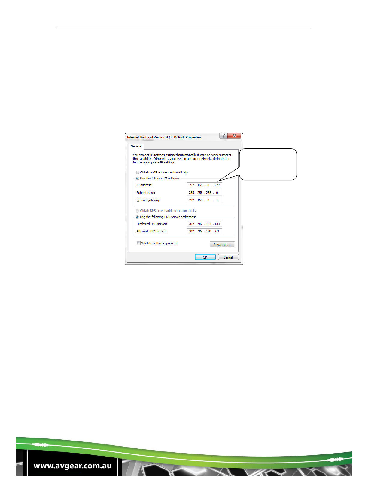
4.5.1. IP Configuration
1. Connect a computer to the TCP/IP port, set its IP to the same IP range as the
default IP of the AVG-SC121D-T (192.168.0.178). As per picture below:
2. Enter the 192.168.0.178 into a browser window, you will see the LOGIN page as
below:
Same IP section
but cannot be
192.168.0.178
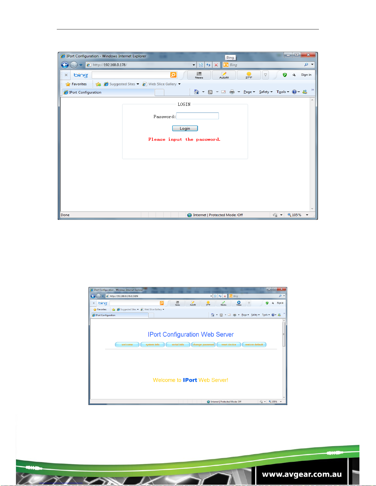
AVG-SC121D-T
3. Enter the password “88888”, and then you can enter the configuration page to
configure the IP port, including the IP reset, PW reset etc. As picture below:
Notice: Serial configuration must be fixed to match the AVG-SC121D-T, so it
cannot be changed.
After configuration, reset device, then you can use the new IP address for control.
Table of contents
Other AVGear Switch manuals

AVGear
AVGear avg-uhs41-v2 User manual

AVGear
AVGear AVG-DSS61 User manual

AVGear
AVGear AVG-UHS24 User manual

AVGear
AVGear AVG-UHC41A User manual

AVGear
AVGear AVG-UHS41 DA User manual

AVGear
AVGear AVG-SC51D User manual

AVGear
AVGear AVG-SM-2.0 User manual

AVGear
AVGear AVG-UHS41 DA User manual

AVGear
AVGear AVG-MS88-HDBT User manual

AVGear
AVGear AVG-CSK-HD44 User manual


Popular Switch manuals by other brands

Hirschmann
Hirschmann RS2-5TX/FX Description and operating instructions

Renkforce
Renkforce RS2W operating instructions

SWI
SWI L312 Installation and operation manual

Bticino
Bticino F80SG manual

ATEN
ATEN Petite CS62US user manual

elsner elektronik
elsner elektronik Nunio KNX M-T Technical specifications and installation instructions


