Intercoax ECP-2808RM User manual

Quick Installation Guide
version 1.1
Ethernet over Coax / UTP Managed Receiving Switch
ECP-2808RM / ECP-2816RM / EUP-2808RM / EUP-2816RM
High-Speed, Long distance Ethernet and PoE Extender
3. Warranty Policy
Intercoax Co.,Ltd. warrants that the product conforms to Intercoax’s applicable published specifications
and it free of defects for 24 months from the date of purchase.
Warranty will only be provided for the product purchased from an Intercoax authorized reseller.
Defective product will be repaired, replaced or substituted with a product of equal value by Intercoax’s option.
This warranty will not be covered for any damages or breakage from user’s abuse, accident, modification
of the device, natural disaster, product fails due to damage from shipment, handling, storage or misuse.
Intercoax’s liability under any warranties shall be discharged by replacing or repairing any part or parts which do
not conform to the applicable warranty under normal and proper use.
Intercoax’s liability with respect to any product shall not exceed a refund of the price received by Intercoax
for that product, and in no event shall Intercoax have any liability for any incidental, consequential, special, or
indirect damages.
4. Regulatory and Certificates
5. Customer supports
Intercoax Co.,Ltd (Korea Head Office)
Address: 51, Simin-daero 365, Dongan-gu, Anyang-si, Gyeonggi-do, Korea (14057)
Tel: +82-31-365-3133 Fax: +82-31-365-3135
Web: www.intercoax.com
INFORMATION TO THE USER
This equipment has been tested and found to comply with the limits for a Class A digital device, pursuant to part 15
of the FCC Rules. These limits are designed to provide reasonable protection against harmful interference when the
equipment is operated in a commercial environment. This equipment generates, uses, and can radiate radio frequency
energy and, if not installed and used in accordance with the instruction manual, may cause harmful interference to
radio communications. Operation of this equipment in a residential area is likely to cause harmful interference in
which case the user will be required to correct the interference at his own expense.
WARNING
Any changes or modifications not expressly approved by the manufacturer could void the user’s authority to
operate the equipment.
Network Solution Provider
High-Speed, Long distance Ethernet and PoE Extender
Network Solution Provider

2. Management Software
1. Under network setting, set your PC’s IP address to 192.168.4.xxx and subnet mask to 255.255.255.0.
2. Open the web browser and enter http://192.168.4.17, the factory default IP address of the ECP Managed Switch.
3. Login window will be opened on web browser.
4. Enter the default User ID, "admin"
5. Enter the default Password, "admin"
6. Open the Setting page and change IP address as desired address.
7. Change Login ID and Password on Admin page of the Intercoax ECP Manager.
7. Connect ECP-Transmitters to IP Camera
( IP it is PoE IP Camera, Please select PoE Switch ‘ON’ from ECP Transmitters)
8. Connect the receiving switch to Network switch, NVR or PC using RJ45 Patch cord.
1. Hardware Installation
1-1. Prepare devices and materials
• Ethernet over Coax / UTP Receiving Switch (ECP-2808RM, EUP-2808RM, ECP-2816RM, EUP-2816RM)
• ECP-Transmitters (ECP-2801, ECP-2701, ECP-2601,ECP-9501, ECP-8401, ECP-8301, & etc)
• EUP-Transmitters (EUP-8401, EUP-2601, EUP-2801 & All ECP-Transmitters with BTE-02)
• RJ-45 patch cord
• Short Coax cable or 4 pairs UTP cable (at least 4 cables for joining)
• Password label (if it is necessary)
• Paper clip (if it is necessary for pressing join button)
• Network Switch, NVR or PC (OS: Window 7 or later recommended)
1-2. Hardware Installation
1. Apply power to the receiving switch
2. Use short coax or UTP cables to connect the receiving switch and the ECP/EUP-Transmitters
3. The blue power LED and B-Linx & T-Linx LED of the receiving switch will be ON.
4. The blue power LED of the ECP/EUP-Transmitters will be ON.
5. The green join LED of the receiving switch and ECP-Transmitters will blink regularly if both devices are
already joined with same network password.
6. If the green Join LED is OFF on both receiving switch and ECP-Transmitter, joining work should be necessary
for network communication.
[Note]
All ECP/EUP products have the same network password as factory default mode
to support plug & play configuration between ECP/EUP Series.
Network Solution Provider
High-Speed, Long distance Ethernet and PoE Extender
[Note]
For joining work, please refer to the joining instructions on page full manual.
Please visit www.intercoax.com to download full manual.
[Note]
Please visit www.intercoax.com
to download ECP Manager.

Quick Installation Guide
version 1.1
Ethernet over Coax / UTP Managed Receiving Switch
ECP-2808RM / ECP-2816RM / EUP-2808RM / EUP-2816RM
High-Speed, Long distance Ethernet and PoE Extender
3. Warranty Policy
Intercoax Co.,Ltd. warrants that the product conforms to Intercoax’s applicable published specifications
and it free of defects for 24 months from the date of purchase.
Warranty will only be provided for the product purchased from an Intercoax authorized reseller.
Defective product will be repaired, replaced or substituted with a product of equal value by Intercoax’s option.
This warranty will not be covered for any damages or breakage from user’s abuse, accident, modification
of the device, natural disaster, product fails due to damage from shipment, handling, storage or misuse.
Intercoax’s liability under any warranties shall be discharged by replacing or repairing any part or parts which do
not conform to the applicable warranty under normal and proper use.
Intercoax’s liability with respect to any product shall not exceed a refund of the price received by Intercoax
for that product, and in no event shall Intercoax have any liability for any incidental, consequential, special, or
indirect damages.
4. Regulatory and Certificates
5. Customer supports
Intercoax Co.,Ltd (Korea Head Office)
Address: 51, Simin-daero 365, Dongan-gu, Anyang-si, Gyeonggi-do, Korea (14057)
Tel: +82-31-365-3133 Fax: +82-31-365-3135
Web: www.intercoax.com
INFORMATION TO THE USER
This equipment has been tested and found to comply with the limits for a Class A digital device, pursuant to part 15
of the FCC Rules. These limits are designed to provide reasonable protection against harmful interference when the
equipment is operated in a commercial environment. This equipment generates, uses, and can radiate radio frequency
energy and, if not installed and used in accordance with the instruction manual, may cause harmful interference to
radio communications. Operation of this equipment in a residential area is likely to cause harmful interference in
which case the user will be required to correct the interference at his own expense.
WARNING
Any changes or modifications not expressly approved by the manufacturer could void the user’s authority to
operate the equipment.
Network Solution Provider
High-Speed, Long distance Ethernet and PoE Extender
Network Solution Provider
Other manuals for ECP-2808RM
3
This manual suits for next models
3
Table of contents
Other Intercoax Switch manuals
Intercoax
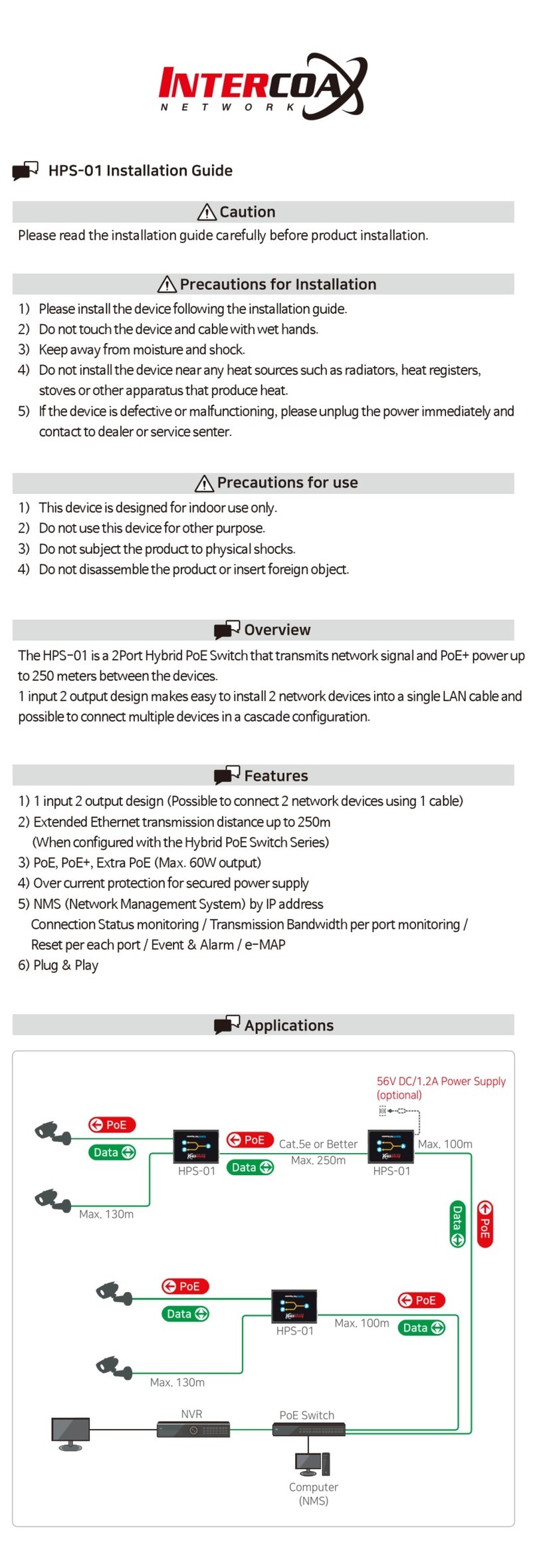
Intercoax HPS-01 User manual
Intercoax
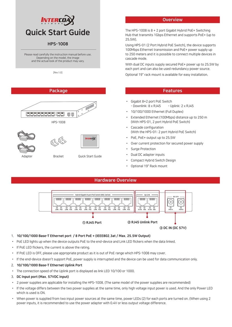
Intercoax HPS-1008 User manual

Intercoax
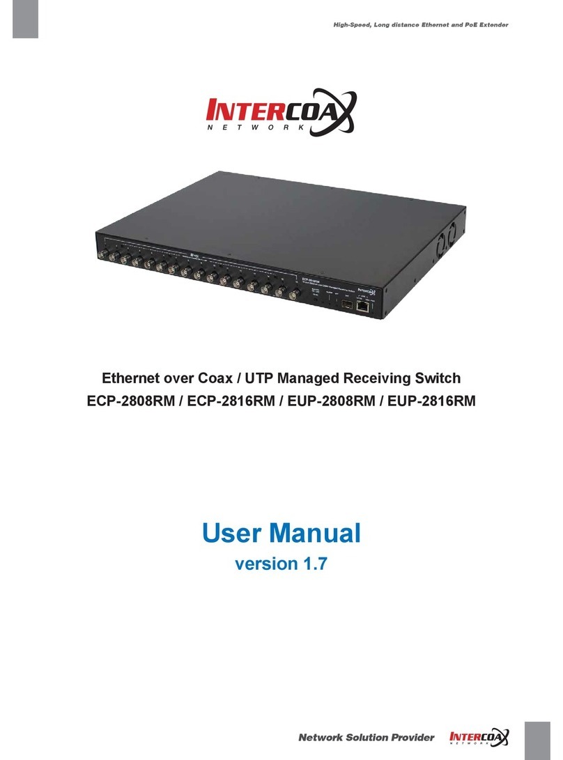
Intercoax ECP-2808RM User manual
Intercoax
Intercoax ECP-2808RM User manual
Intercoax
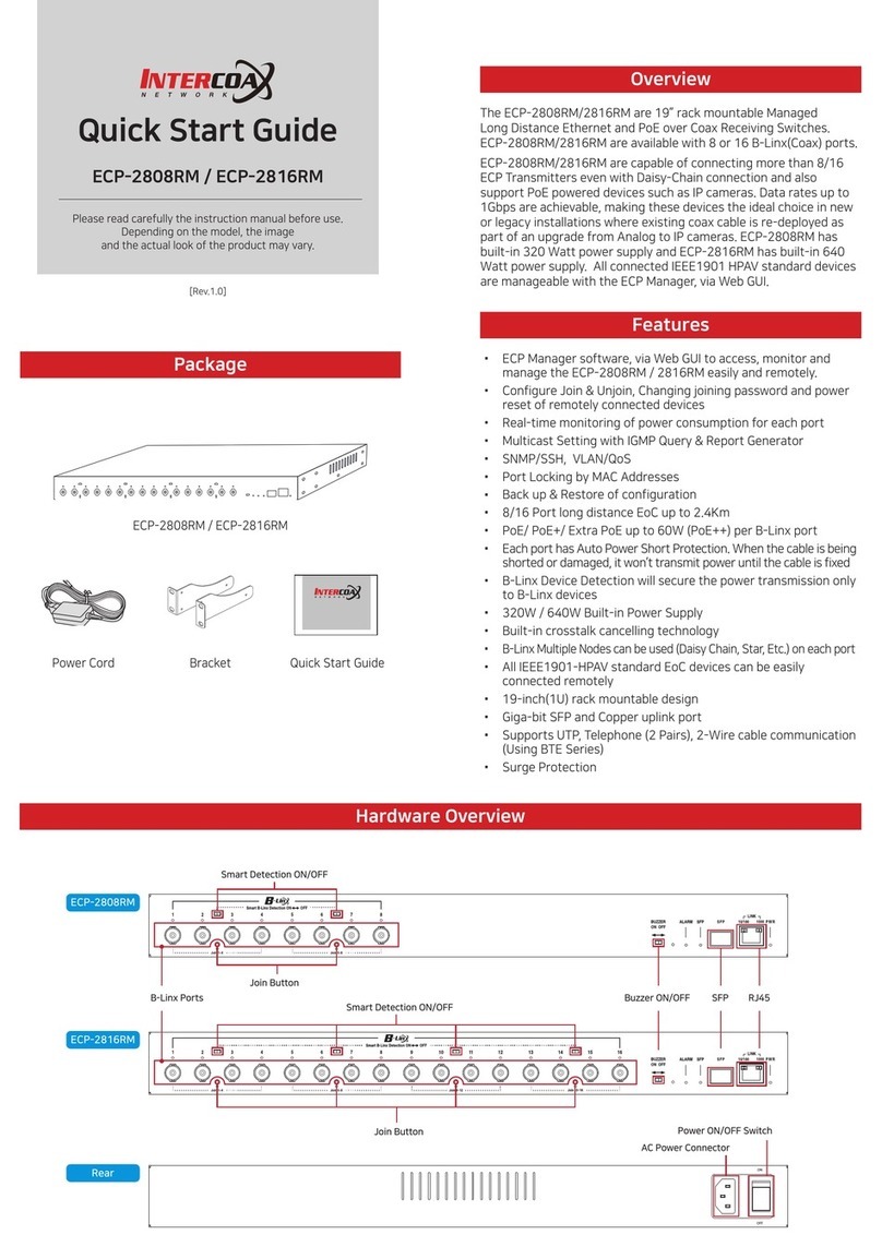
Intercoax 2816RM-ECP User manual
Intercoax
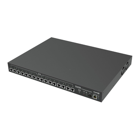
Intercoax EUP-2816RM User manual
Intercoax
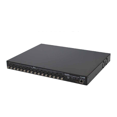
Intercoax ECP-2808RM User manual

Intercoax
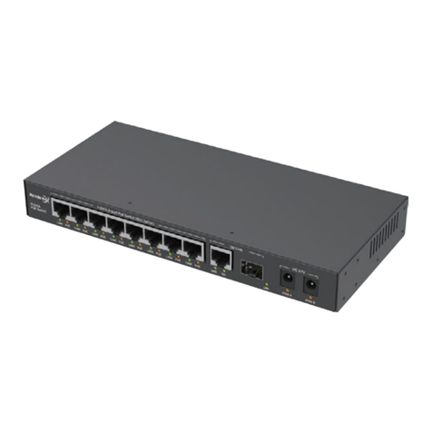
Intercoax HPS-01 User manual
Intercoax
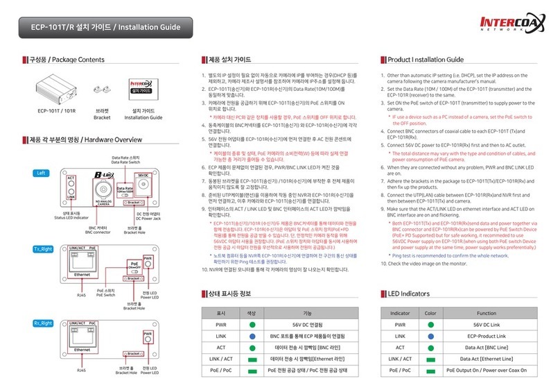
Intercoax ECP-101T User manual
Intercoax
Intercoax FLX-1008 User manual

