manuals.online logo
Brands
  1. Home
  2. •
  3. Brands
  4. •
  5. Intermatic
  6. •
  7. Lighting Equipment
  8. •
  9. Intermatic EL200 Series Guide

Intermatic EL200 Series Guide

Power Failure Path Lighting
Remove existing receptacle from the wall box (if necessary).
Strip building wires to 7/16”.
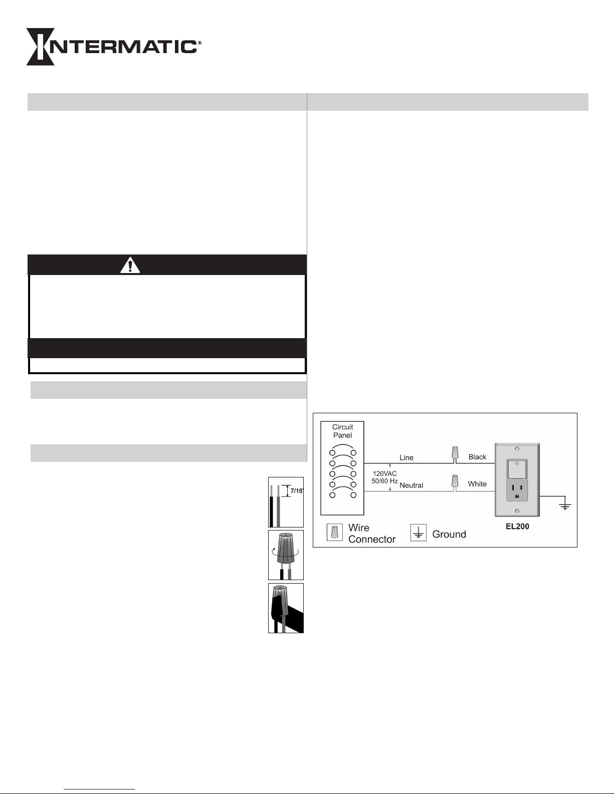
Connect the BLACK wire to the line building wire, us-
ing a twist connector (provided).
Connect the WHITE wire to the neutral building wire,
using a twist connector (provided).
NOTE: Insert wires straight into twist connector, then
twist clockwise. Make sure all twist connectors are tight.
Secure each twist connector with electrical tape. Make
sure no bare wire shows below the twist connector.
Connect the ground wire from the box to the GREEN
screw on the EL200 unit. If there is no ground wire,
ground the EL200 unit to the box. If using a plastic box,
connect to ground as supplied.
Tuck wires into wall box leaving room for the EL200
unit.
Using screws provided, mount the EL200 unit to the wall box,
then install wall plate.
Turn power back on at the service panel.
1.
2.
3.
4.
5.
6.
7.
8.
Voltage — 120 Volts, 60 Hz
Colors — White, Ivory, Light Almond
Consumption — 17.0 watts max.
Receptacle Amperage — 15 Amps General Purpose
Battery — Single rechargeable 2/3A NiMH provides 1.5 hours life
in use.
Light Source — 3 high-output white LEDs
Temperature Operating Range — 32°F to 104°F / 0°C to 40°C
Storage Range — -31°F to 158°F / -35°C to 70°C
Environmental — 10% to 95% non-condensing relative humidity
For Indoor Use Only
•
•
•
•
•
•
•
•
•
•
Installation and User Instructions
MODEL EL200 Series
Turn off power at the service panel by REMOVING FUSE or
TURNING THE CIRCUIT BREAKER OFF.
Test to VERIFY that the power is off.
1.
2.
Before You Begin
Installation Instructions
Specifications
The EL200 Series unit can be operated in ve different modes.
NOTE: After installation, the battery reaches maximum charge in
about one week.
Night Light ON — Press the lens once when the night light is
OFF and the night light will come ON at 25% of full brightness.
In this mode the night light is powered by the building current.
Night Light OFF — Press the lens once when the night light is
ON and the night light will power OFF.
Power Failure Light ON — When building current is discon-
nected (e.g., during a power failure), the power failure light will
automatically come ON at 100% of full brightness and remain lit
until the battery is discharged (1.5 hours at a full charge). NOTE:
As the battery runs out of power, the unit will begin to ash and
will continue to do so until all power is drained from the battery
or power is restored.
Power Failure Light OFF — When the power failure light is ON
(and the unit is operating on battery power), press and hold the
lens for 5 or more seconds to manually turn it OFF. NOTE: You
can press and hold the lens again for 5 or more seconds to turn
the light back ON.
Battery Test — After battery has had a minimum of 1 week to
charge, press and hold the lens for 5 seconds to switch the unit
from building current to battery power which turns ON the light
at the 100% brightness level. If the light doesn’t come on, the
battery is dead or damaged. Releasing the lens will switch the
unit back into normal operation.
•
•
•
•
•
How To Operate the EL200 Series
Electrical shock hazard. To avoid fire, shock, or death, turn off power
at circuit breaker and test that power is off before wiring.
Follow local electrical codes during installation.
Connect to copper conductors only.
Connect to Class 1 wiring only.
•
•
•
•
WARNING
No user-serviceable parts.•
NOTICE
LIMITED ONE-YEAR WARRANTY
If within one (1) year from the date of purchase, this product fails due to a defect in material or workmanship, Intermatic Incorporated will repair or replace it, at its sole option, free of charge. This
warranty is extended to the original household purchaser only and is not transferable. This warranty does not apply to: (a) damage to units caused by accident, dropping or abuse in handling, acts
of God or any negligent use; (b) units which have been subject to unauthorized repair, opened, taken apart or otherwise modified; (c) units not used in accordance with instructions; (d) damages
exceeding the cost of the product; (e) sealed lamps and/or lamp bulbs, LED’s and batteries; (f) the finish on any portion of the product, such as surface and/or weathering, as this is considered
normal wear and tear; (g) transit damage, initial installation costs, removal costs, or reinstallation costs.
INTERMATIC INCORPORATED WILL NOT BE LIABLE FOR INCIDENTAL OR CONSEQUENTIAL DAMAGES. SOME STATES DO NOT ALLOW THE EXCLUSION OR LIMITATION OF INCIDENTAL OR CONSE-
QUENTIAL DAMAGES, SO THE ABOVE LIMITATION OR EXCLUSION MAY NOT APPLY TO YOU. THIS WARRANTY IS IN LIEU OF ALL OTHER EXPRESS OR IMPLIED WARRANTIES. ALL IMPLIED WARRAN-
TIES, INCLUDING THE WARRANTY OF MERCHANTABILITY AND THE WARRANTY OF FITNESS FOR A PARTICULAR PURPOSE, ARE HEREBY MODIFIED TO EXIST ONLY AS CONTAINED IN THIS LIMITED
WARRANTY, AND SHALL BE OF THE SAME DURATION AS THE WARRANTY PERIOD STATED ABOVE. SOME STATES DO NOT ALLOW LIMITATIONS ON THE DURATION OF AN IMPLIED WARRANTY, SO THE
ABOVE LIMITATION MAY NOT APPLY TO YOU.
This warranty service is available by either (a) returning the product to the dealer from whom the unit was purchased, or (b) mailing the product, along with proof of purchase, postage prepaid
to the authorized service center listed below. This warranty is made by: Intermatic Incorporated/After Sales Service/7777 Winn Rd., Spring Grove, Illinois 60081-9698/815-675-7000 http://www.
intermatic.com Please be sure to wrap the product securely to avoid shipping damage.
INTERMATIC INCORPORATED
SPRING GROVE, ILLINOIS 60081-9698
158EL13264
44” Max.
16“ Max.
4” Max.
The mounting height of the power failure light to be in accordance
with local and national codes but is not to exceed 18 inches above
the nished oor height.
The maximum spacing between power failure lights not to exceed
44 inches.
The spacing between a corner of a wall or change in direction of the
power failure light not to exceed 4 inches.
•
•
•
Install as shown below to provide safety when power failure occurs (in compliance with UL 1994).

Other Intermatic Lighting Equipment manuals

Intermatic EL100 Guide

Intermatic

Intermatic EL100 Guide

Intermatic T40000RT Series Manual

Intermatic

Intermatic T40000RT Series Manual

Intermatic PE1501RC User manual

Intermatic

Intermatic PE1501RC User manual

Intermatic EL500E Guide

Intermatic

Intermatic EL500E Guide

Intermatic Malibu LZ3W User manual

Intermatic

Intermatic Malibu LZ3W User manual

Intermatic EL200W Guide

Intermatic

Intermatic EL200W Guide

Intermatic EL500 Guide

Intermatic

Intermatic EL500 Guide

Intermatic IPURE PE25K120V User manual

Intermatic

Intermatic IPURE PE25K120V User manual

Intermatic RC4G Manual

Intermatic

Intermatic RC4G Manual

Popular Lighting Equipment manuals by other brands

OCEM LHI Instruction Manual for Use, Installation and Maintenance

OCEM

OCEM LHI Instruction Manual for Use, Installation and Maintenance

Photonic HPRL operating manual

Photonic

Photonic HPRL operating manual

Federal Signal Corporation VIEWPOINT SOLARIS Installation and maintenance instructions

Federal Signal Corporation

Federal Signal Corporation VIEWPOINT SOLARIS Installation and maintenance instructions

RH CADE DOUBLE SCONCE Assembly & installation

RH

RH CADE DOUBLE SCONCE Assembly & installation

Chauvet DJ 4 BAR LT QuadBT ILS Quick reference guide

Chauvet DJ

Chauvet DJ 4 BAR LT QuadBT ILS Quick reference guide

Optika CL-14 instruction manual

Optika

Optika CL-14 instruction manual

Bowens BW3370 UNILITE Operating instrctions

Bowens

Bowens BW3370 UNILITE Operating instrctions

RANCEO See Snake CL15 instruction manual

RANCEO

RANCEO See Snake CL15 instruction manual

BenQ WiT MindDuo AR19 D user guide

BenQ

BenQ WiT MindDuo AR19 D user guide

DÖRR Ultra 60 instruction manual

DÖRR

DÖRR Ultra 60 instruction manual

Westcott Eyelighter 3 quick start guide

Westcott

Westcott Eyelighter 3 quick start guide

INTER LIGHT Thinq manual

INTER LIGHT

INTER LIGHT Thinq manual

Bowens CREO 1200 Owner's handbook

Bowens

Bowens CREO 1200 Owner's handbook

EuroLite LED KLS-10 COMPACT LIGHT SET user manual

EuroLite

EuroLite LED KLS-10 COMPACT LIGHT SET user manual

GOLDLUX LONGER quick start guide

GOLDLUX

GOLDLUX LONGER quick start guide

EcoSmarte Pool System manual

EcoSmarte

EcoSmarte Pool System manual

Life 39.9F70020C quick start guide

Life

Life 39.9F70020C quick start guide

SWITCH MADE JUPY-X user manual

SWITCH MADE

SWITCH MADE JUPY-X user manual

manuals.online logo
manuals.online logoBrands
  • About & Mission
  • Contact us
  • Privacy Policy
  • Terms and Conditions

Copyright 2025 Manuals.Online. All Rights Reserved.