MA860 MicrosteppingDriverManual V1.0
Tel:+086 0755-264343693WebSite: www.leadshine.com
EliminationofHeat
lDriver sreliableworkingtemperatureshouldbe<70 (158℉),and motorworkingtemperature
shouldbe<80 (176℉);
lItisrecommendedtouseautomaticidle-currentmode,namelycurrentautomaticallyreduceto
60%whenmotorstops,soastoreducedriverheatingandmotorheating;
lIt isrecommendedtomountthedriververticallytomaximize heatsinkarea. Useforcedcooling
methodtocool thesystem ifnecessary.
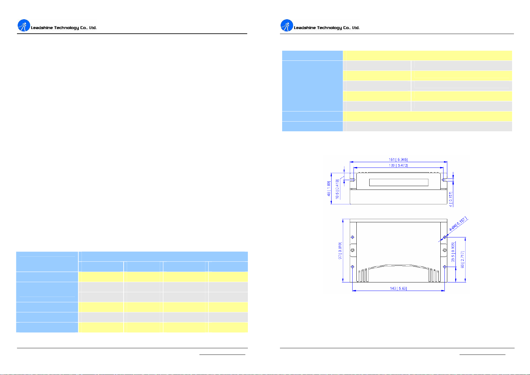
3. PinAssignmentand Description
TheMA860 hastwoconnectors,connectorP1forcontrolsignalsconnections,and connectorP2for
powerandmotorconnections.Thefollowingtablesarebriefdescriptionsofthetwoconnectors.
Moredetaileddescriptionsofthepinsandrelatedissuesarepresentedinsection4,5, 9.
ConnectorP1 Configurations
PinFunction Details
PUL+
PUL-
Pulsesignal: Insinglepulse(pulse/direction)mode,thisinputrepresentspulse
signal,activeateachrisingorfallingedge(setbyinsidejumperJ3);4-5V
whenPUL-HIGH,0-0.5VwhenPUL-LOW.Indoublepulsemode
(pulse/pulse), thisinputrepresentsclockwise(CW)pulse,activeat highlevel
orlowlevel(setbyinsidejumperJ3).Forreliableresponse,pulsewidth
shouldbelongerthan1.5μs.Seriesconnectresistorsforcurrent-limitingwhen
+12Vor+24Vused. ThesameasDIRandENAsignals.
DIR+
DIR-
DIRsignal: Insingle-pulsemode,thissignalhaslow/highvoltagelevels,
representingtwodirectionsofmotorrotation;indouble-pulsemode(setby
insidejumperJ1),thissignaliscounter-clock(CCW)pulse,activeathigh
levelorlowlevel(setbyinsidejumperJ3).Forreliablemotionresponse,DIR
signalshouldbeaheadofPULsignalby5μsatleast.4-5VwhenDIR-HIGH,
0-0.5VwhenDIR-LOW.Pleasenotethatmotion directionisalsorelatedto
motor-driverwiringmatch.Exchangingtheconnectionoftwowiresforacoil
tothedriverwill reversemotiondirection.
ENA+
ENA-
Enablesignal: Thissignalisusedforenabling/disablingthedriver.Highlevel
(NPNcontrolsignal,PNPand Differentialcontrolsignalsareonthecontrary,
namelyLowlevelforenabling.)forenablingthedriverandlowlevelfor
disablingthedriver.Usuallyleft UNCONNECTED (ENABLED).
Selecting EffectivePulseEdgeorEffectiveLevelandControlSignalMode
TherearetwojumpersJ1andJ3insidetheMA860specificallyforselectingactivepulseedgeor
effectiveleveland controlsignalmode,asshowninfigure2.DefaultsettingisPUL/DIRmodeand
upward-risingedgeactive.(Note:J2insidethedriverisusedtoreversethedefaultrotationdirection.)
MA860 MicrosteppingDriverManual V1.0
Tel:+086 0755-264343694WebSite: www.leadshine.com
(a)J1, J3opencircuit (b)J1opencircuit, J3shirtcircuit
PUL/DIRmode andActive atrisingedge (NPN) PUL/DIRmode andactive atfalling edge (NPN)
(c)J1shortcircuit, J3opencircuit (d)J1, J3shortcircuit
CW/CCWmode andactive atlowlevel(The fixedlevel)CW/CCWmode and active athigh level(The fixedlevel)
Figure 2:J1andJ3jumpers
ConnectorP2 Configurations
PinFunction Details
AC
AC
Powersupply,18~60VACor24~80VDC,Includingvoltagefluctuation
and EMFvoltage.
A+,A- MotorPhaseA
B+, B- MotorPhaseB
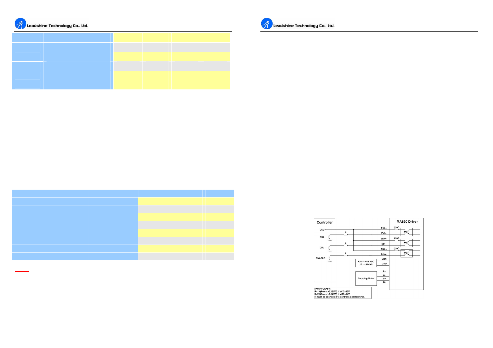
4. ControlSignalConnector(P1)Interface
TheMA860 canacceptdifferentialandsingle-endedinputs(includingopen-collectorandPNP
output). TheMA860 has3opticallyisolatedlogicinputswhicharelocatedonconnectorP1toaccept
linedrivercontrol signals.Theseinputsareisolatedtominimizeoreliminateelectricalnoisescoupled
ontothedrivecontrolsignals.Recommend uselinedrivercontrolsignalstoincreasenoiseimmunity
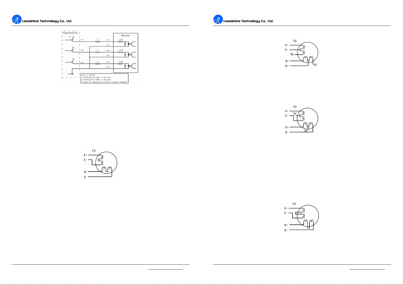
ofthedriverininterferenceenvironments. Inthefollowingfigures,connectionstoopen-collectorand
PNPsignalsareillustrated.
Figure 3:Connectionstoopen-collectorsignal(common-anode)