International Biomedical AeroNOx User manual

AeroNOx
Portable Nitric Oxide
Titration & Monitoring System
Where “NO Man
” has gone before.....
Operating Manual
0086

Document No. 715-7000 Revision E Page 1 of 63
AeroNOx
Portable Nitric Oxide
Titration & Monitoring System
Operating Manual
Phone: (512) 873-0033
Toll Free: 1-800-433-5615
Fax: (512) 873-9090
Website: http://www.int-bio.com
Mailing address:
International Biomedical
8508 Cross Park Dr.
Austin, TX 78754
USA
Authorized representative in Europe for Regulatory Affairs:
Emergo Europe
Molenstraat 15
2513 BH
The Hague, The Netherlands
0086

Document No. 715-7000 Revision E Page 2 of 63

Document No. 715-7000 Revision E Page 3 of 63
AeroNOx
Table of Contents
SECTION I - IMPORTANT INFORMATION ABOUT NITRIC OXIDE DELIVERY........................ 5
SECTION II - UNPACKING AND SET-UP INSTRUCTIONS ....................................................... 6
AeroNOxTransport P/N 731-9148..............................................................................................7
AeroNOxBedside .....................................................................................................................15
AeroNOxPortable Cylinder Cart and Platform.......................................................................... 21
SECTION III - DEVICE DESCRIPTION...................................................................................... 23
General .......................................................................................................................................23
Recommended Use ....................................................................................................................23
Back-Up System .........................................................................................................................25
Titration Delivery System ............................................................................................................28
NO / NO2and O2Sampling.........................................................................................................29
Electrochemical Sensors ............................................................................................................30
Analysis ......................................................................................................................................30
Alarms.........................................................................................................................................31
“Safety” Shut Off .........................................................................................................................31
Front Panel .................................................................................................................................32
Gas Connections ........................................................................................................................33
Quick Connect Gas Fittings ........................................................................................................33
Luer Lock Connections ...............................................................................................................34
Battery ........................................................................................................................................35
Universal Power Supply..............................................................................................................37
SECTION IV - SPECIFICATIONS .............................................................................................. 38
Functional Performance..............................................................................................................38
Physical Specifications ...............................................................................................................41
Safety..........................................................................................................................................41
SECTION V - CALIBRATION..................................................................................................... 42
AeroNOxCalibration Procedure ...............................................................................................43
SECTION VI - NITRIC OXIDE DELIVERY ................................................................................. 45
Inspiratory Limb NO Titration in Constant Flow Ventilators.........................................................45
Precautions for Inspiratory Limb NO Titration .............................................................................45
Ventilators Safe for Use with the AeroNOx...............................................................................45
Nitric Oxide Concentration Profiles .............................................................................................46
SECTION VII - CALCULATIONS & TROUBLESHOOTING ...................................................... 47
Calculations for Nitric Oxide Delivery..........................................................................................47
What is the diluted FiO2? ............................................................................................................ 49
Oxygen Index Calculation ...........................................................................................................49
Calculation of Cylinder Duration .................................................................................................51
How much calibration gas do I need?.........................................................................................52
AeroNOxTroubleshooting Guide..............................................................................................53

Document No. 715-7000 Revision E Page 4 of 63
AeroNOx
Table of Contents
SECTION VIII - CLEANING & MAINTENANCE......................................................................... 57
Cleaning......................................................................................................................................57
Repairs and Replacement ..........................................................................................................57
Customer Service .......................................................................................................................57
Instructions for Disposal..............................................................................................................58
SECTION IX - WARRANTY ....................................................................................................... 59
SECTION X - COMPETENCY BASED PERFORMANCE CHECK-OFF TOOL.........................61
Routine (Weekly) AeroNOxCalibration ....................................................................................62
AeroNOxPortable & Bedside Set-Up .......................................................................................63

Document No. 715-7000 Revision E Page 5 of 63
SECTION I - IMPORTANT INFORMATION ABOUT
NITRIC OXIDE DELIVERY
ATTENTION!
AeroNOxNitric Oxide Titration & Monitoring System delivers nitric oxide gas and
measures nitric oxide and nitrogen dioxide gas concentrations in parts per million (ppm).
“Caution: U. S. Federal and Canadian law restricts this device to sale by or on the order
of a physician or other licensed medical practitioner. Outside Canada and the U. S.,
check with local laws for applicable restrictions.”
“Persons using this device should be trained and experienced in the use of this device to
assure effective administration of nitric oxide, and to avoid injury to the patient or to
others resulting from inhalation of excess nitric oxide, nitrogen dioxide, or other reaction
products.”
“Persons using this device who may be particularly sensitive to nitric oxide or nitrogen
dioxide, or who may be exposed to these gases for prolonged periods as a result of the
use of this device, should be aware that the AeroNOxdoes not scavenge the exhaust
gas, and that this gas is vented from the underside of the AeroNOx, or through the side
vent in the event that the bottom port is occluded. Ambient concentrations of nitric oxide
or nitrogen dioxide expected to result from the use of this device are less than 50 ppb.”
WARNING
The use of oxygen increases the danger of fire. Auxiliary equipment producing sparks should
not be placed near the AeroNOx. Small quantities such as ether or alcohol left near the
AeroNOx can cause fire.
Classification
According to the standard EN60601-1 of the International Electrotechnical Commission,
Medical electrical equipment, Part 1: General requirements for safety, the AeroNOxis
classified as follows:
Class I / Internally Powered, according to the type of protection against electric
shock.
Ordinary, according to the degree of protection against harmful ingress of water.
Continuous operation for the mode of operation.

Document No. 715-7000 Revision E Page 6 of 63
SECTION II - UNPACKING AND SET-UP INSTRUCTIONS
Verify that the shipping carton (s) contain one of the following groups of equipment. Complete
descriptions of these groupings can be found in this section.
1. AeroNOxTransport, P/N 731-9148
Nitric Oxide Titration & Monitoring System
2. AeroNOxBedside Option
Nitric Oxide Titration & Monitoring System
Document No. 715-7000 Revision E Page 7 of 63
The AeroNOx
Transport P/N 731-9148
Nitric Oxide Titration & Monitoring System
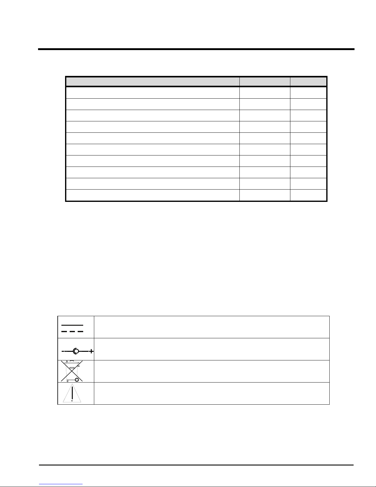
Component Part Number Quantity
AeroNOx731-9138 1
SS Hose with Quick Connect (3 ft.) 731-9371 1
AeroNOxOperating Manual 715-7000 1
AeroNOxTechnical Manual 715-7001 1
12 V Universal Power Supply 293-0040 1
Medical Grade Power Cord 711-0179 1
SS NO Transport Delivery Regulators, CGA 626 731-9142 2
AeroNOx“NO WORRIES” Connector Sample Pak 731-9373 1
AeroNOxCalibration Circuit 415-0000 1
Single Calibration Screwdriver 416-0010 1
The AeroNOxmust be used with calibration gas and
accessories specified by the manufacturer.
Symbols
The following symbols appear in the AeroNOx documentation and labels. These
internationally recognized symbols are defined by the International Electrotechnical
Commission, IEC 417A and IEC 878 or by the Institute of Electrical and Electronics
Engineers, 315(a).
Direct current
Positive to center pin, Negative to outer ring of connection
Recycle or dispose of properly, contains sealed lead batteries
Attention, consult accompanying documents

Document No. 715-7000 Revision E Page 8 of 63
The AeroNOx
Transport P/N 731-9148
Nitric Oxide Titration & Monitoring System
Prepare the AeroNOx
Transport Nitric Oxide
Titration & Monitoring System
for initial operation as follows:
1. Unpack the AeroNOxand inspect for damage.
2. Install battery as per SECTION III, “Battery”.
3. Unpack 12 V universal power supply (P/N 293-0040) and Medical Grade Power Cord
(P/N 711-0179). Plug in AeroNOxand charge for ~ 24 hrs.
4. Calibrate AeroNOx. (See SECTION V.)
5. Attach CGA 626 regulators to the transport tanks as per “Purge procedures to follow
when changing tanks and/or regulators” in this section.
6. Connect selected regulator outlet to the AeroNOxgas inlet using the stainless steel hose
with quick connect adapters.
7. Turn on nitric oxide gas supply.
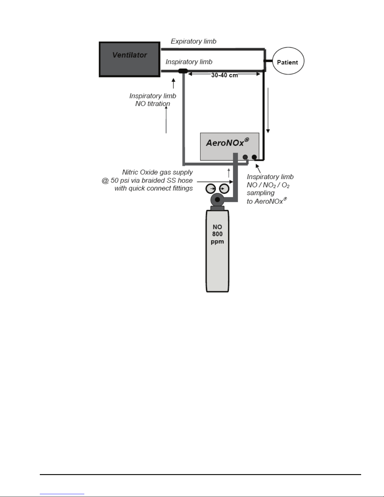
8. Attach the delivery line from the AeroNOxBagger (See Diagram # 2) or the AeroNOx
delivery line (P/N 415-0001) found in the AeroNOx“NO WORRIES” connector sample
pak to the female luer connector marked “NITRIC OXIDE DELIVERY OUTLET” on the
AeroNOx. Tee the other end of the delivery line into the patient breathing circuit at least
30 - 40 cm upstream of the sampling site (see Diagram # 1).
9. Attach the “NO WORRIES” sample line (P/N 415-0004) to the male luer connector
marked “ANALYSIS SAMPLE INLET” on the AeroNOx.
10. Select the appropriate sample gas connector from your “NO WORRIES” connector
sample pak and attach it to the free end of the sample line. *NB if attaching the sample
line to the bagger, skip this step.
11. Connect the sample gas connector to the patient breathing circuit. The connector should
be placed in the inspiratory limb, just prior to the patient wye connection (refer to Diagram
# 1).
OR
Connect the sample line to the sampling port on the bagger (see Diagram # 2).
12. “Flush” your system according to “Suggested flush procedure for the delivery portion of
the AeroNOxsystem”, or according to the instructions for the AeroNOxBagger.
13. You are now ready to deliver NO gas and sample mixed inspired gases.
CAUTION!
Never turn on the NO delivery gas without first turning on the
ventilator or bagger flow. Failure to do this will result in undiluted
delivery gas entering the sampling chamber and exposing the
sensors to levels of NO and/or NO2which may damage the
sensors.
CAUTION!
NO2gas may have collected in the AeroNOxdelivery circuitry. Prior
to delivering gas to the patient, “flush” your delivery system with
fresh NO delivery gas. This should be repeated every time you begin
NO gas administration. Analyze the gas for high NO2levels prior to
patient connection.

Document No. 715-7000 Revision E Page 9 of 63
Suggested “flush” procedure for the delivery portion of the AeroNOxsystem:
1. Set up the AeroNOxfor delivery as outlined in “AeroNOxTransport Nitric Oxide
Titration & Monitoring System for initial operation”.
2. Hook up the ventilator to a test lung (patient should be manually ventilated during this
procedure and the ventilator parameters should be set to the patient’s pre-NO gas
settings).
3. Inactivate the “Safety Shut Off” system by simultaneously depressing the NO and NO2
alarm silence buttons for 5 seconds or until the display reads “SAFETY OFF”. For more
information on the “Safety Shut Off” system, see “Safety Shut Off” in SECTION III.
4. Turn on the NO gas flow to 2 lpm by turning the knob on the precision metering valve in a
counter-clockwise direction. This knob is located in the bottom right hand quadrant of the
front panel of the AeroNOxbelow the LCD flow display. Allow the gas to flow into the
ventilator circuit.
5. As soon as the NO2value has dropped to a stable level, allow the gas to run for an
additional 3 seconds and then adjust the NO flow to the desired level (see SECTION VII -
Calculations for NO Delivery to determine flow required for desired NO concentration).
6. Re-activate the “Safety Shut Off” system by simultaneously depressing the NO and NO2
alarm silence buttons for at least 5 seconds or until the display reads “SAFETY ON”.
7. Once the desired NO concentration has been reached, ensure that NO2level is
acceptable for patient administration. Below you will find a table which will give you the
approximate NO2values you can expect for a given NO concentration and ventilator flow
at an FiO2of 1.0.
Minute Volume / Ventilator Flow
[NO] 5 10 15 20
5 ppm 0.5 0.1 0.1 0.1
10 ppm 0.5 0.2 0.2 0.1
20 ppm 0.5 0.3 0.2 0.2
40 ppm 0.8 0.6 0.4 0.4
80 ppm 2.0 1.5 1.2 1.1
NO2in PPM
The table above is for reference only.
Factors such as the accuracy of the ventilator flow, percent error in delivery apparatus,
and human error, may all affect the actual delivered patient dose. The calculated NO flow
should be compared with the analyzed NO dose to confirm accurate NO dosing. Should
the actual NO flow differ from the calculated NO flow by more than 10% beyond
published specifications, the cause must be determined and corrected immediately. If the
cause can not be immediately determined, ensure patient safety and contact International
Biomedical at 1-800-433-5615 for further assistance.
8. Connect the patient to the ventilator and monitor according to study and/or institution
protocol.
CAUTION!
The flush procedure must be performed each time NO therapy is
started. This includes initial therapy starts, tank changes, and re-
starting therapy after trials off NO.

Document No. 715-7000 Revision E Page 10 of 63
Purge Procedures to follow when changing tanks and/or regulators.
Important!
Purge Procedure Required before Use
Please follow purge instructions below to ensure gas purity. Failure to follow these
instructions may introduce potentially harmful contaminants into the patient’s
breathing gas or may affect the monitoring analyzer’s accuracy by introduction of
contaminants into the calibration gas.
Warning:Perform cylinder connection and purge procedures in well-ventilated areas
to prevent inadvertent exposure to nitric oxide or nitrogen dioxide gas. Follow your
facility’s safety procedures for handling medical gas cylinders.
Purge Procedures for use with Medical Gas Regulators:
1. Connect cylinder to a matching CGA nitric oxide or nitrogen dioxide
regulator only.
2. Open, then immediately close the cylinder valve.
3. Release (bleed) all of the gas from the regulator.
4. Repeat steps 2 and 3 four more times for a total of five purge cycles.
5. Leave the regulator installed until it is time to change to a new cylinder.
6. Repeat the purge procedure any time a regulator is reattached.
Any time a regulator is installed on a tank or cylinder of compressed gas, certain precautions
must be followed. This is to prevent contamination of the gas in the tank and in the system by
air that is trapped in the dead space of the regulator and fittings. To eliminate the possibility of
the oxygen in this air reacting with the nitric oxide to form nitrogen dioxide in the system, the
regulator and fittings must be purged before use. The valve on the tank must not be opened
and left open until the regulator is purged. The stainless steel line must also be purged prior to
connection to the AeroNOx.
CAUTION!
Should there be a sudden need to change therapy tanks, a second tank
should always be purged and ready for immediate use. Perform the
purge procedure immediately upon installation of a new regulator.
Although the dead space volume in the regulator and hose assembly is physically small, if it had
been exposed to room air for a period of time it will contain sufficient oxygen to convert a
significant amount of nitric oxide to nitrogen dioxide.

Document No. 715-7000 Revision E Page 11 of 63
The following purge procedure must be followed any time a regulator is installed on a tank of
gas. It should be done immediately after connecting a regulator to a tank to avoid contaminating
a tank of gas with the air trapped in the dead space of the regulator in the event someone turns
on and leaves on the valve on the tank.
1. Install and tighten the regulator onto the tank.
2. Insert the quick-connect on one end of the stainless steel hose into the quick-connect
fitting on the regulator. Leave the other end of the stainless steel hose free.
3. Crack open and immediately close the tank valve.
4. Gently press the center tip of the quick-connect on the free end of the stainless steel hose
against a clean hard surface and allow the pressure to bleed to zero. A small amount of
high concentration delivery gas will be released at 50 psig. Keep the hose away from
patients and clinicians in order to avoid exposure to the gas.
5. Repeat Step 3 and Step 4 above five times (five complete purge cycles).
6. Connect equipment and open the tank valve as needed.
Any time a regulator is installed onto a cylinder and before each patient use, the
AeroNOxsystem should be purged. - NO EXCEPTIONS!!
AeroNOxBagger: Instructions for use with the AeroNOx
(See Diagram # 2.)
CAUTION!
Oxygen and Nitric Oxide mix in the reservoir bag and stagnant flow will cause NO2to be
formed. Turn off NO flow when not actively bagging patient. Flush the bagger with
oxygen for a least 20 seconds to completely remove NO and NO2before and after patient
use.
Concentrations of nitrogen dioxide in the reservoir bag may exceed 1 ppm. Large tidal
volumes may expose patients to the nitrogen dioxide in the reservoir bag.
Flush the bagger with oxygen for at least 20 seconds to completely remove NO and NO2
after any interruption in active patient bagging.
The AeroNOxmay not be able to detect rapid, short acting fluctuations in the
concentration of the delivered gas, including nitrogen dioxide. For this reason, the
AeroNOxBagger is designed for short-term use only.
If a patient requires nitric oxide concentrations other than 20 ppm, a separate system
capable of providing the required concentration must be available. DO NOT USE THE
AERONOXBAGGER TO DELIVER CONCENTRATIONS IN EXCESS OF 20 PPM!
The generation of nitrogen dioxide increases rapidly above this concentration.
Do not alter the length of the Bagger Gas Supply Tubing as this may cause generation of
excessive levels of nitrogen dioxide.

Document No. 715-7000 Revision E Page 12 of 63
Do not substitute AeroNOxBagger components! The AeroNOxBagger has been
designed and tested for patient safety with the components included in the current
configuration.
The AeroNOxBagger is designed for use only with the AeroNOxDelivery System. Do
not attempt to use the AeroNOxwith any other manual resuscitator. Do not attempt to
use the AeroNOxBagger with any other delivery system.
A backup system must always be available in the event that the primary system should
fail. For instructions for use of a Back-Up System in the event of a failure of the
AeroNOxsystem, please see SECTION III, Back-Up system.
The AeroNOxBagger is intended to be connected directly to the patient’s endotracheal
tube. Do not insert any additional tubing between the AeroNOxBagger and the
endotracheal tube.
The AeroNOxBagger is for single patient use only. Do not reprocess.
Persons using this device should be trained and experienced in the use of this device to
assure affective administration of nitric oxide, and to avoid injury to the patient or to
others resulting from inhalation of excess nitric oxide, nitrogen dioxide, or other reaction
products.
Persons using this device who may be particularly sensitive to nitric oxide, or who may be
exposed to these gases for prolonged periods as a result of the use of this device, should
be aware that the gases exiting the AeroNOxBagger are not scavenged.
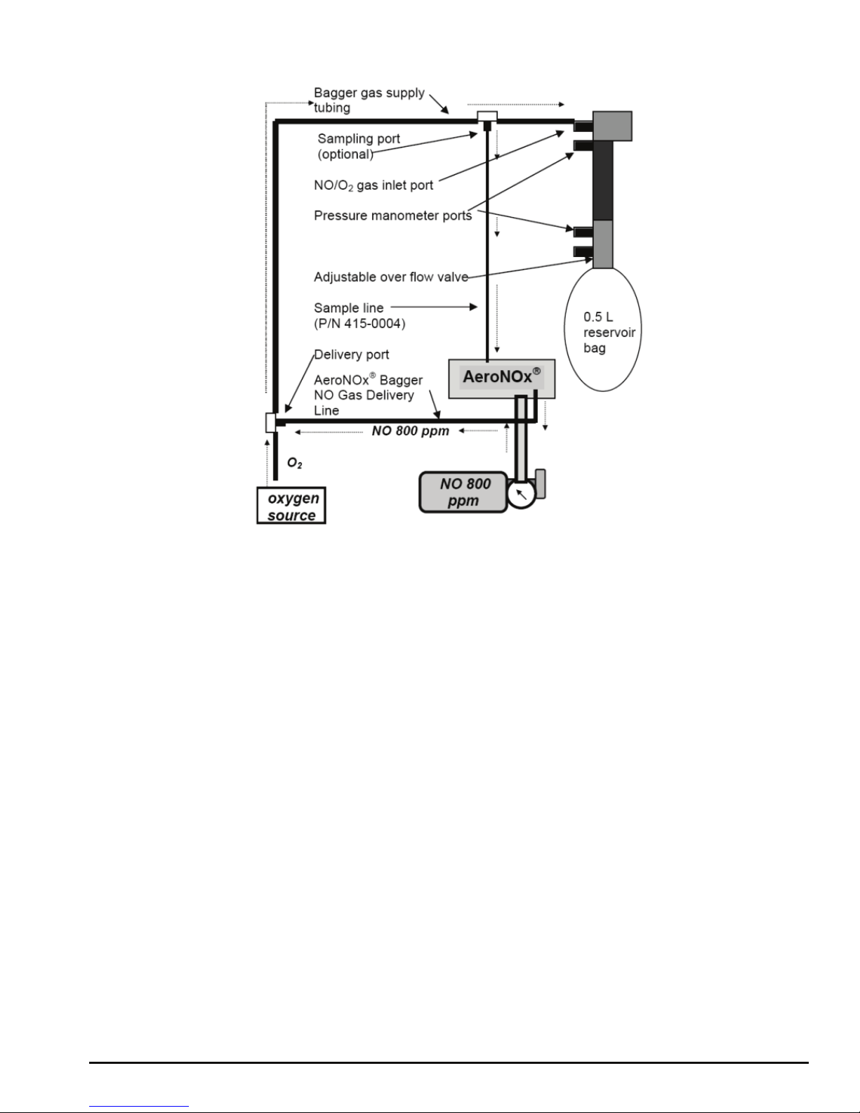
1. Connect the large end of the bagger gas supply tubing to an oxygen source. Ensure that
the small end of this tubing is connected to the NO / O2gas inlet port on the bagger.
2. Connect AeroNOxBagger gas delivery line to the AeroNOxdelivery gas port.
3. Connect male end of the sample line (P/N 415-0004) to the sampling port on the bagger
gas supply tubing and the female end to the AeroNOxsampling port.
4. Set O2flow on the O2flow meter to exactly 10 LPM. Let the oxygen run for at least 20
seconds to flush out any residual NO or NO2left in the AeroNOxBagger.
5. Turn on NO delivery gas source to 0.25 LPM. If you have correctly set your O2flow at
exactly 10 LPM, the delivered NO concentration will be ~20 ppm and delivered NO2
values should not exceed 0.2 ppm. Do not exceed 20 ppm during manual ventilation!
6. Connect test lung and set overflow valve to desired positive end expiratory pressure
(PEEP).

Document No. 715-7000 Revision E Page 13 of 63
7. Continue to run the AeroNOxBagger with the test lung until the analyzed NO and NO2
values stabilize. This will prevent high doses of NO2, which can form in the bagger and
delivery line, from being delivered to your patient. The NO2sensor in the AeroNOx
Bagger may not react quickly enough to detect NO2boluses.If you do not have time
to use a test lung, in an emergency situation for example, you must still flush the
bagger with fresh gas for at least 20 seconds prior to patient connection!
8. Analyze NO and NO2concentration prior to patient administration.
9. Flush bagger with O2after each patient use to flush out residual NO and prevent
NO2formation.
AeroNOxBagger Specifications:
O2Gas Flow 10 LPM
NO Gas Flow 0.25 LPM
Delivered [NO] ~ 20 ppm
NO2Generated Maximum 0.2 ppm @ 20 ppm Delivered [NO]
Reservoir Volume 0.5 L
Bagger Dimensions 12” from Reservoir Bag to Patient Connection, ½” I. D.
Tidal Volume Maximum 0.5 L (500 cc)
Breath Rate
Maximum 100 bpm at Pressures 18/5 (pip/peep)
Maximum 50 bpm at Pressures 40/5
(Pressures Listed in cmH2O)
I:E Ratio Variable
Diagram # 1
NO Titration with a Transport Ventilator
Document No. 715-7000 Revision E Page 14 of 63
Diagram # 2 NO Titration with AeroNOxBagger

Document No. 715-7000 Revision E Page 15 of 63
The AeroNOx
Bedside
Nitric Oxide Titration & Monitoring System
Component Part Number Quantity
AeroNOx731-9138 1
AeroNOxOperating Manual 715-7000 1
AeroNOxTechnical Manual 715-7001 1
AeroNOxCart including Stand, Platform, Basket, & Power Bar 1
AeroNOxMounting Block 1
12 V Universal Power Supply 293-0040 1
SS Hose with Quick Connect Fittings 731-9371 1
Medical Grade Power Cord 711-0179 1
CGA 626 NO Delivery Regulators 731-9142 2
AeroNOx“NO WORRIES” Connector Sample Pak 731-9373 1
AeroNOxCalibration Circuit 415-0000 1
Single Calibration Screwdriver 416-0010 1
Recommended Bedside Gases: (Not Included)
Concentration: 800 ppm NO in balance N2of pharmaceutical
grade gas
Size: 38” (1 meter) height by 7” (18 cm) diameter
2
The AeroNOxmust be used with calibration gas and accessories
specified by the manufacturer.

Document No. 715-7000 Revision E Page 16 of 63
The AeroNOx
Bedside Set-Up
Prepare the AeroNOx
Bedside Nitric Oxide Titration & Monitoring System
for initial operation as follows:
1. Unpack the AeroNOxand inspect for damage.
2. Install battery as per SECTION III, “Battery”.
3. Secure the therapeutic tanks to the AeroNOxcart.
4. Unpack 12 V universal power supply (P/N 293-0040) and Medical Grade Power Cord
(P/N 711-0179). Plug in AeroNOxand charge for ~ 24 hrs.
5. Calibrate AeroNOxusing the Calibration Kit (P/N 731-9145) NO and NO2Calibration
Gas specified by the manufacturer and the instructions found in SECTION V of this manual.
6. Attach CGA 626 regulators (P/N 731-7142) to delivery gas cylinders as per “Purge
procedures to follow when changing tanks and/or regulators” in this section.
7. Connect selected regulator outlet to the AeroNOxgas inlet using the stainless steel hose
with quick connect adapters.
8. Turn on nitric oxide gas supply.
9. Attach the AeroNOxdelivery line (P/N 415-0001) found in the AeroNOx“NO
WORRIES” connector sample pak to the female luer connector marked “NITRIC OXIDE
DELIVERY OUTLET” on the AeroNOx. Tee the other end of the delivery line into the
patient breathing circuit at least 30 - 40 cm upstream of the sampling site. Attach the “NO
WORRIES” sample line (P/N 415-0004) to the male luer connector marked “ANALYSIS
SAMPLE INLET” on the AeroNOx.
10. Select the appropriate sample gas connector from your “NO WORRIES” connector
sample pak and attach it to the free end of the sample line.
11. Connect the sample gas connector to the patient breathing circuit. The connector should
be placed in the inspiratory limb, just prior to the patient wye connection (refer to Diagram
# 3).
12. “Flush” your system according to “Suggested “flush” procedure for the delivery portion of
the AeroNOxsystem”.
13. You are now ready to deliver NO gas and sample mixed inspired gases.
CAUTION!
Never turn on the NO delivery gas without first turning on the
ventilator or bagger flow. Failure to do this will result in undiluted
delivery gas entering the sampling chamber and exposing the sensors
to levels of NO and/or NO2which may damage the sensors.
CAUTION!
NO2gas may have collected in the AeroNOxdelivery circuitry. Prior
to delivering gas to the patient, “flush” your delivery system with
fresh NO delivery gas. This should be repeated every time you begin
NO gas administration. Analyze the gas for high NO2levels prior to
patient connection.

Document No. 715-7000 Revision E Page 17 of 63
Suggested “flush” procedure for the delivery portion of the AeroNOxsystem:
1. Set up the AeroNOxfor delivery as outlined in “AeroNOxBedside Set-Up”.
2. Hook up the ventilator to a test lung (patient should be manually ventilated during this
procedure and the ventilator parameters should be set to the patient’s pre-NO gas
settings).
3. Inactivate the “Safety Shut Off” System by simultaneously depressing the NO and NO2
alarm silence buttons for 5 seconds or until the display reads “SAFETY OFF”. For more
information on the “Safety Shut Off” system, see “Safety Shut Off” in SECTION III.
4. Turn on the NO gas flow to 2 lpm by turning the knob on the precision metering valve in a
counter-clockwise direction. This knob is located in the bottom right hand quadrant of the
front panel of the AeroNOxbelow the LCD flow display. Allow the gas to flow into the
ventilator circuit.
5. As soon as the NO2value has dropped to a stable level, allow the gas to run for an
additional 3 seconds and then adjust the NO flow to the desired level (see SECTION VII -
Calculations for NO Delivery to determine flow required for desired NO concentration).
6. Re-activate the “Safety Shut Off” system by simultaneously depressing the NO and NO2
alarm silence buttons for at least 5 seconds or until the display reads “SAFETY ON”.
7. Once the desired NO concentration has been reached, ensure that NO2level is
acceptable for patient administration. Following, you will find a table which will give you
the approximate NO2values for a given NO concentration and ventilator flow at an FiO2of
1.0.
Minute Volume / Ventilator Flow
[NO] 5 10 15 20
5 ppm 0.5 0.1 0.1 0.1
10 ppm 0.5 0.2 0.2 0.1
20 ppm 0.5 0.3 0.2 0.2
40 ppm 0.8 0.6 0.4 0.4
80 ppm 2.0 1.5 1.2 1.1
NO2in PPM
The table above is for reference only.
Factors such as the accuracy of the ventilator flow, percent error in delivery apparatus,
human error, and accuracy of calibration of the AeroNOxmay all affect the actual
delivered patient dose. The calculated NO flow should be compared with the analyzed
NO dose to confirm accurate NO dosing. Should the actual NO flow differ from the
calculated NO flow by more than 10% beyond published specifications, the cause must
be determined and corrected immediately. If the cause can not be immediately
determined, ensure patient safety and contact International Biomedical at 1-800-433-
5615 for further assistance.
8. Connect the patient to the ventilator and monitor according to study and/or institution
protocol.
CAUTION!
The flush procedure must be performed each time NO therapy is
started. This includes initial therapy starts, tank changes, and re-
starting therapy after trials off NO.
Document No. 715-7000 Revision E Page 18 of 63
Diagram # 3 AeroNOxBedside Set-Up
The Sensormedics 3100A or 3100B
To set up the AeroNOxfor use with the 3100A & 3100B, tee in the AeroNOxDelivery Line
(P/N 415-0001) immediately post humidifier. To connect the “NO WORRIES” sample line, you
will require the 3100A / 3100B sample port adapter (P/N 415-0009). The port can be placed in
one of three positions. All three positions are labeled as “temperature probe ports” in the
3100A / 3100B literature. The “set back” temperature port is pictured in Figure 1 and Figure 2.
The proximal temperature port is pictured in Figure 3. The third port (not shown) is the second
proximal temperature probe port located next to the “dump valve” on the inspired limb of the
flexible circuit.

Document No. 715-7000 Revision E Page 19 of 63
Sampling Ports for the Sensormedics 3100A / 3100B:
Figure 1 The “Set Back” Temperature Probe Port
Figure 2 The “Set Back” Temperature Probe Port
Other manuals for AeroNOx
1
Table of contents
Popular Laboratory Equipment manuals by other brands


Belden
Belden HIRSCHMANN RPI-P1-4PoE installation manual

Koehler
Koehler K1223 Series Operation and instruction manual

Globe Scientific
Globe Scientific GCM-12 quick start guide

Getinge
Getinge 86 SERIES Technical manual

CORNING
CORNING Everon 6000 user manual

Biocomp
Biocomp GRADIENT MASTER 108 operating manual


