International Surrey Company South Coast Cruzer Slingshot User instructions
1
Parts included in Two Slingshot Boxes
Frame Box
Component Box
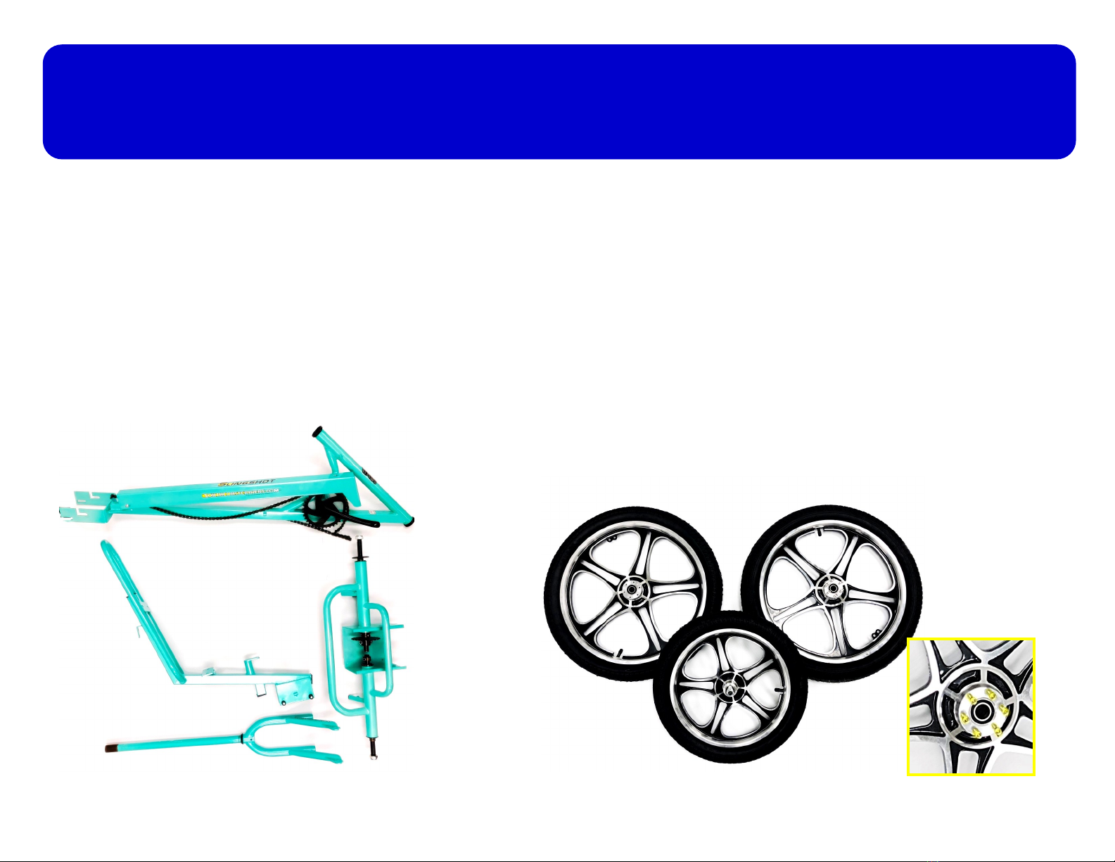
Frame Components
• Front Frame Chassis
• Rear Frame Chassis
• Seat Frame
• Fork
Wheels
• Front Wheel
• Rear Drive Wheel (Has 6 bolts see below -right side install)
• Rear Freewheel Wheel (le side install)
Assembly and Operating Manual
Slingshot
by South Coast Cruzers of International Surrey Company Ltd.
2
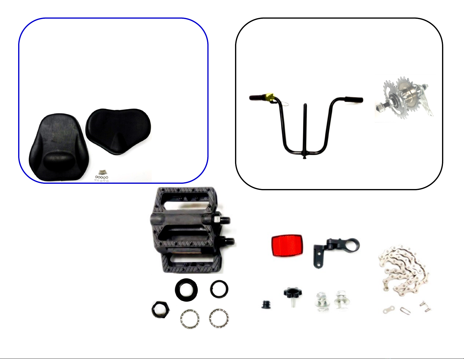
Seat Components
• Backrest Seat
• Boom Seat
• Five bolts, at washers and
lock washers (hardware will be
in a plasc bag)
Assembly Components
• Pair of Pedals
• Reector
• Rear chain with masterlink
• Two (2) chassis carriage bolts
• Flag pole receptor plug
• Flag pole receptor bolt
• Headset Parts (2 bearings, top
race, lock washer, lock nut)
Single Speed Opon
• Single Speed Hub
• Handlebar and handlebar stem without twist shier
(highlighted in yellow)
Note: Only the 5 Speed model will have the twist shier on the
handlebar, highlighted in yellow
3
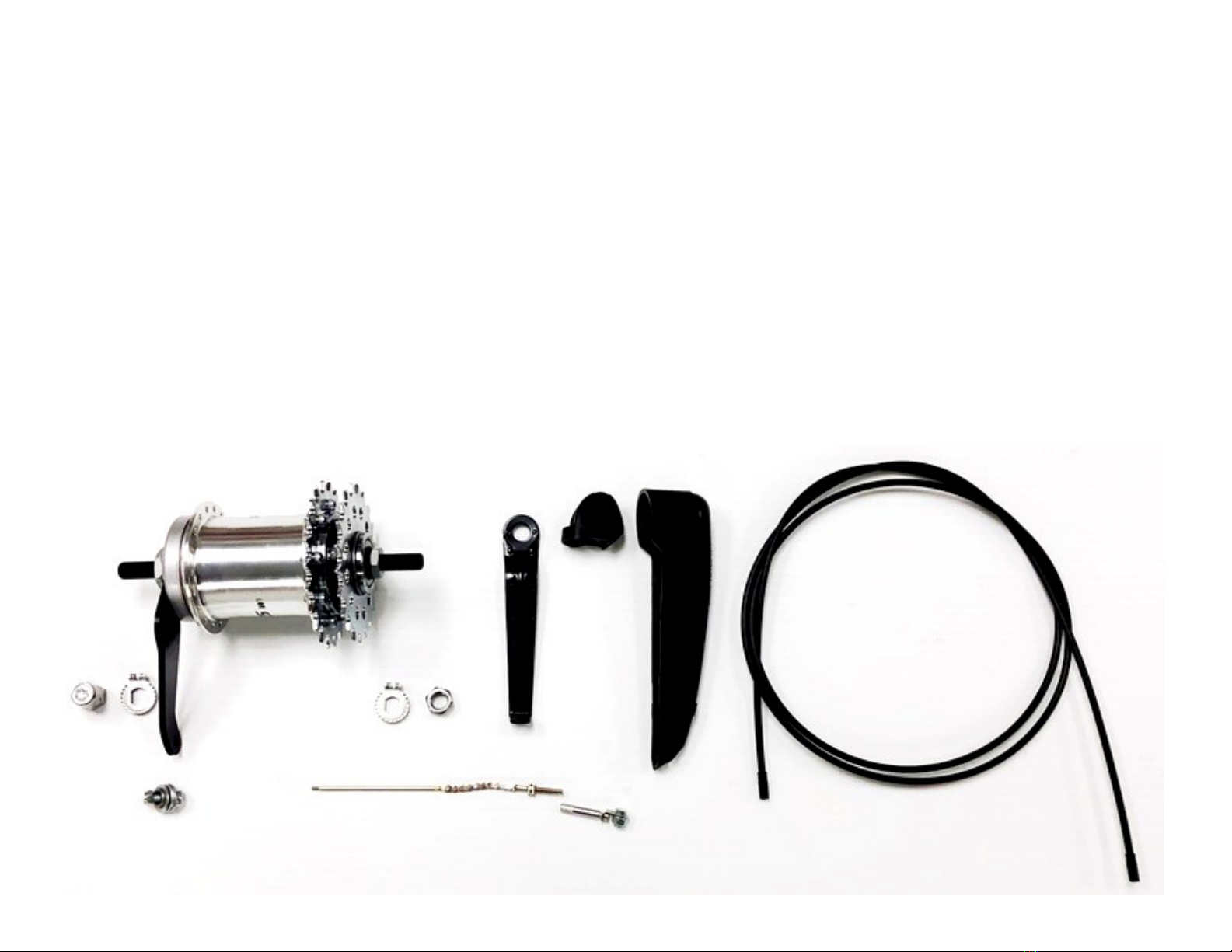
Oponal Sturmey Archer Internal 5 Speed Gearing
• Handlebar and handlebar stem with twist shier (highlight in
yellow)
• Five Speed Hub
• 2 Nonturn lock washers
• 1 Dome nut
• 1 Axle nut
• 1 Fulcrum Lever
• 1 Cable connector with Binder Bolt
• Gear guide with pivot and jackscrew
• Gear guide cover
• Shiing wire (installed in shier on handlebar)
• Shiing wire housing
• Indicator rod with chain
4
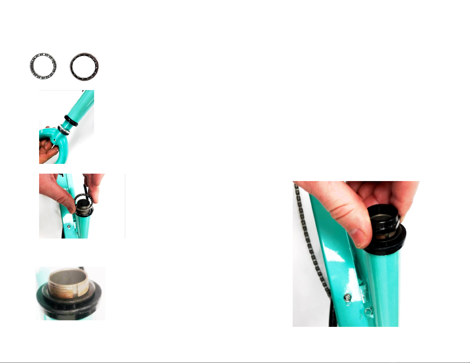
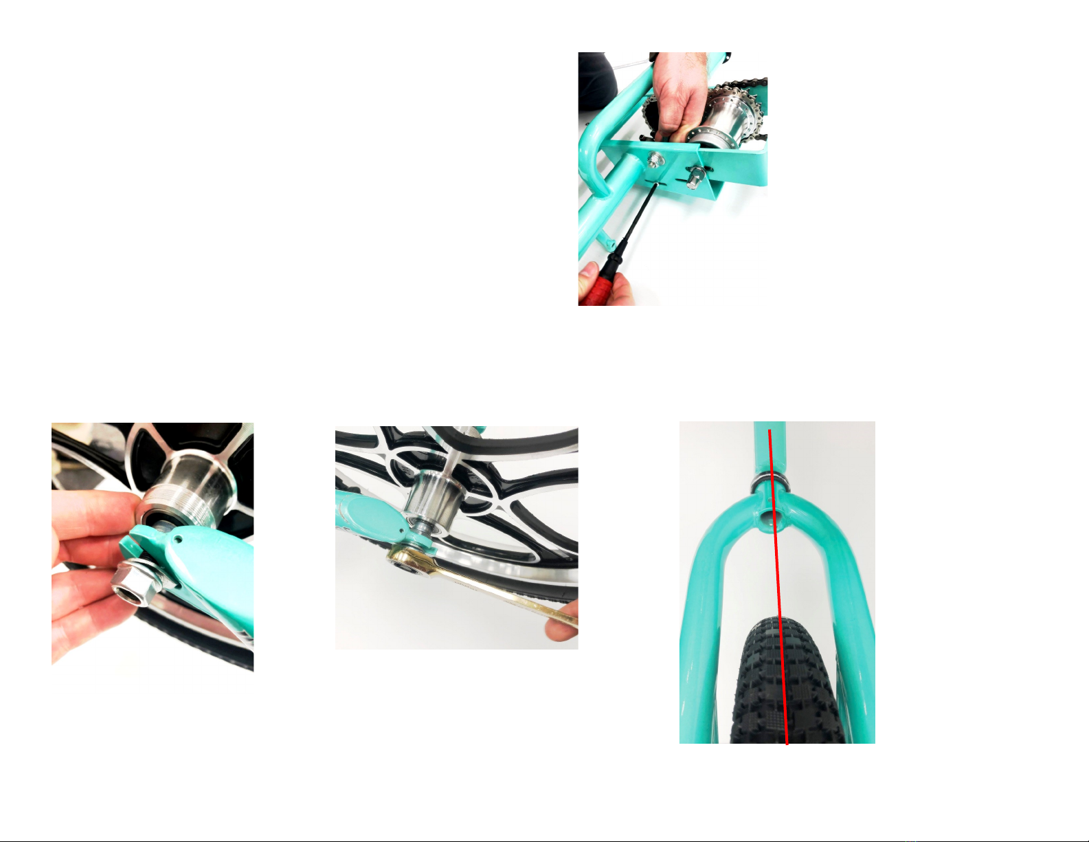
STEP 1 headset and fork installation
A. The set of headset bearings on the le are laying
opposite of each other. On the le, it is bearing side
up. On the right, the bearing side is down. How,
they are installed in the headtube is very important.
B. Aer applying some type of grease in the black
cups at the top and boom of the head tube of the
frame, slide a bearing over the fork with the bearing
side up as shown on the le.
C. Make sure the boom bearing is seeded properly
in the boom cup, next install the top bearing with
the bearing side down. This means the bearing sides
of the bearing set will face each other, both turning
smoothly in the black bearing cups already installed
in the headtube of the trike.
D. Aer both bearings are installed, install the top
race by hand turning it clockwise on the threaded
part of the fork unl it is hand ght. Check to make
sure the fork will not move up and down or le to
right. The fork should only turn le and right freely.
Next, locate the groove in the fork thread and slide
the lock washer down the fork with the lock washer
tongue inside the groove.
E. Lastly, aer again insuring the top race
is hand ght, install the lock nut on top of
the lock washer. Use a large wrench to
ghten the lock washer snuggly. You will
need to stop the fork from turning during
this process.
5
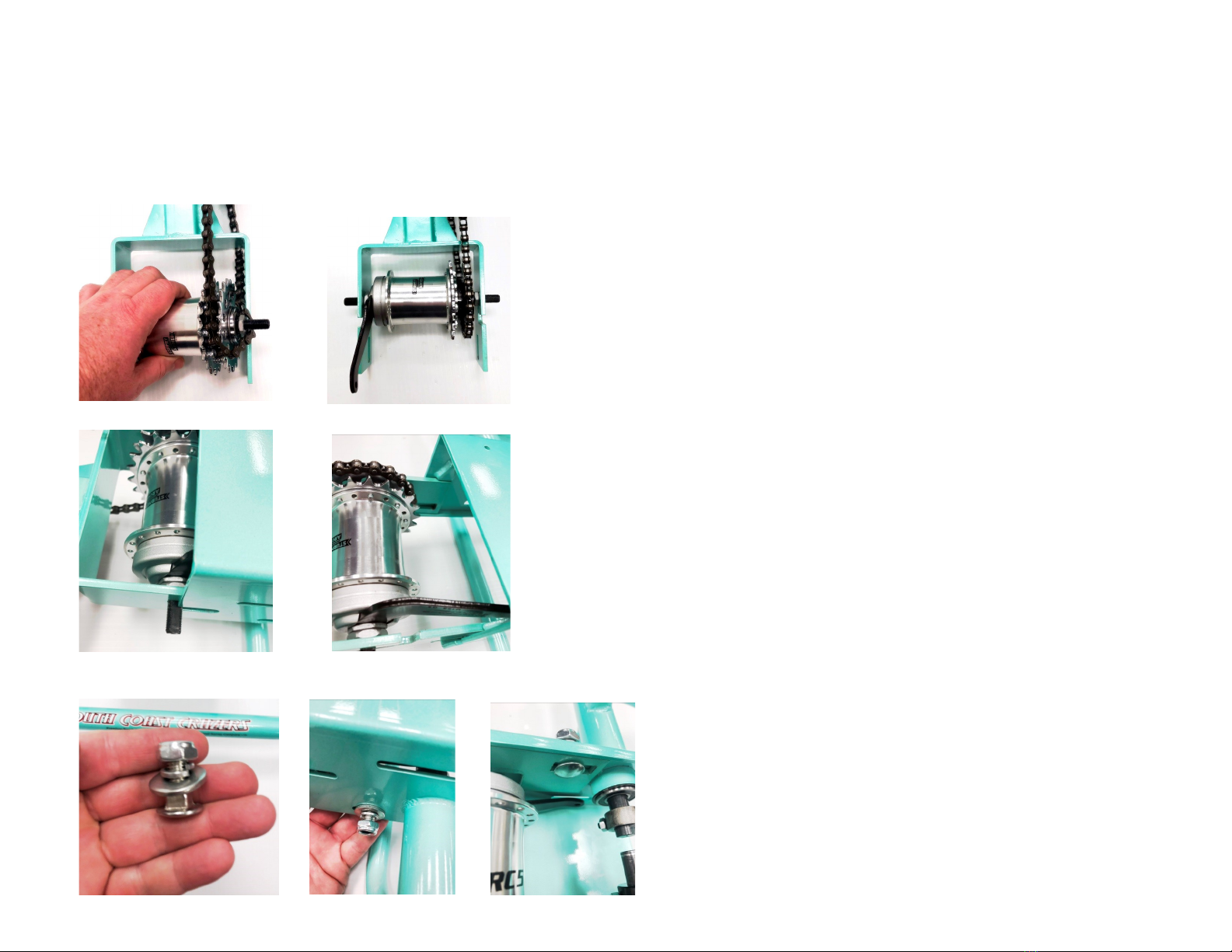
STEP 2 Hub—Transmission / Front and Rear Chassis Installation
These instrucons will demonstrate installaon of the 5 Speed hub, which include the same fundamental steps as the single speed model. The 5
Speed model will require some addional steps that will be details but can be skipped by owners of the single speed model.
A. Place the front frame chassis in front of you. Loop the prein-
stalled chain over the axle. Slide the hub into the sloed part of
the frame (with the at areas of the axle on the 5 Speed on the
top and boom). With the hub as forward was possible, loop the
chain over and around the sprocket on the right side.
B. Next, slide the front frame chassis into the rear frame chassis
as shown the photos on the le. (Again on the 5 Speed, the at
areas on the top and boom of the axle should slide the same
way into the front and rear frame chassis.
C. With the front and rear frame chassis complete engaged into
each other, use the two carriage bolts to secure the each chassis
to the other. Slide the carriage bolts into the slots on each side of
the rear chassis entering from inside with the threaded part of the
bolt extending to the outside of the frame. Install the at washer,
lock washer and the nut. Leave the nut hand ght at this me.
6
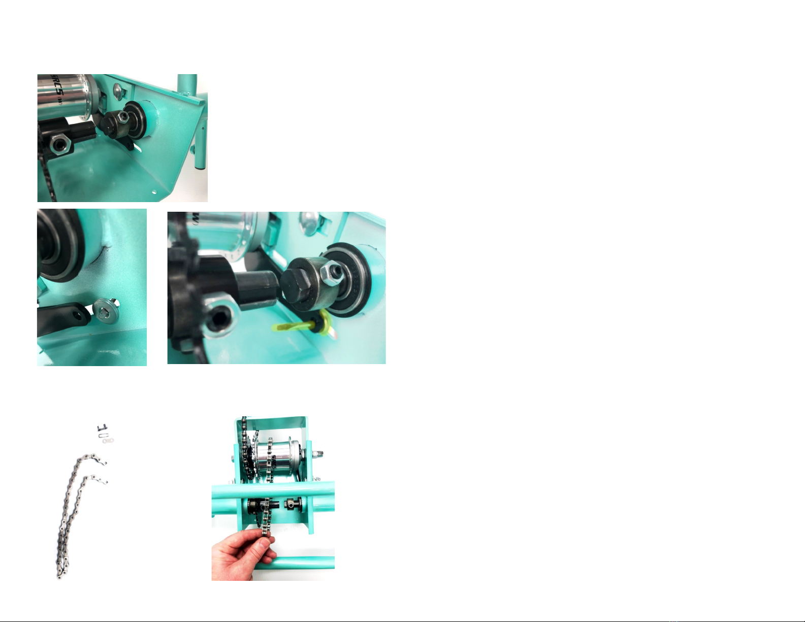
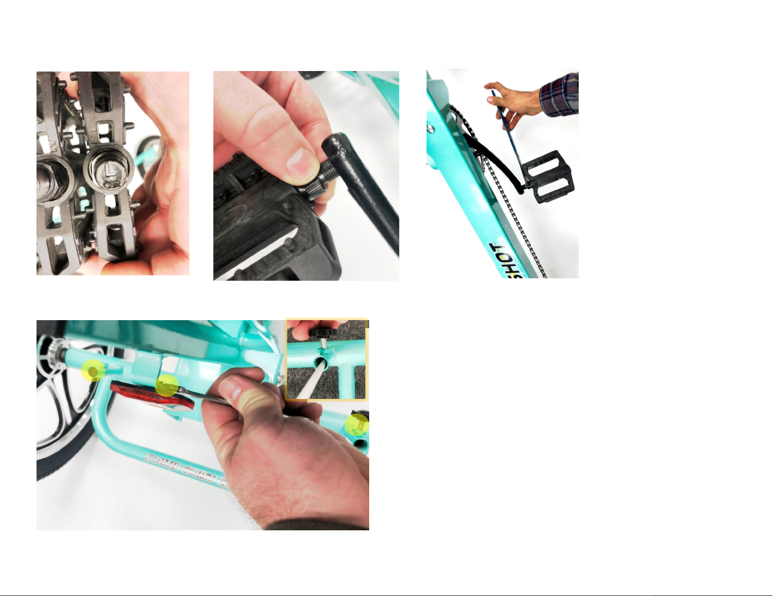
STEP 2 Continued
The next several procedures are accomplished while the trike is upside
down in order to more easily access the boom of the chassis.
D. The photo on the le shows the inside part of the underside of the
rear chassis with the hub in place. Next, connect the brake stabilizer
bar from the coaster brake to the rear chassis. This step is important
because it aects brake funcon on the trike. Using 2-3 of supplied
washers and a small screwdriver, slide the washers into place between
the brake arm and the inside of the chassis wall. See the yellow high-
lighted area.
From the outside, replace the screwdriver with the bolt, holding the
washers in place. You might press the stabilizer arm against the wall of
the chassis to bind the washers in place as you slide the bolt through
the wall of the chassis, the washers and the brake arm. Install the nut
nger ght at this me.
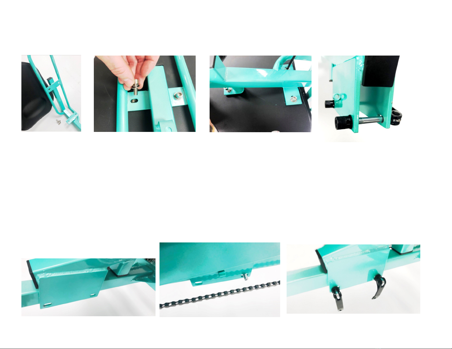
STEP 3 Rear Chain Installation
A. Locate the chain and masterlink. Loop the chain over the body of
the installed hub and around the drive axle. Connect the two ends
of the chain with the masterlink.
7
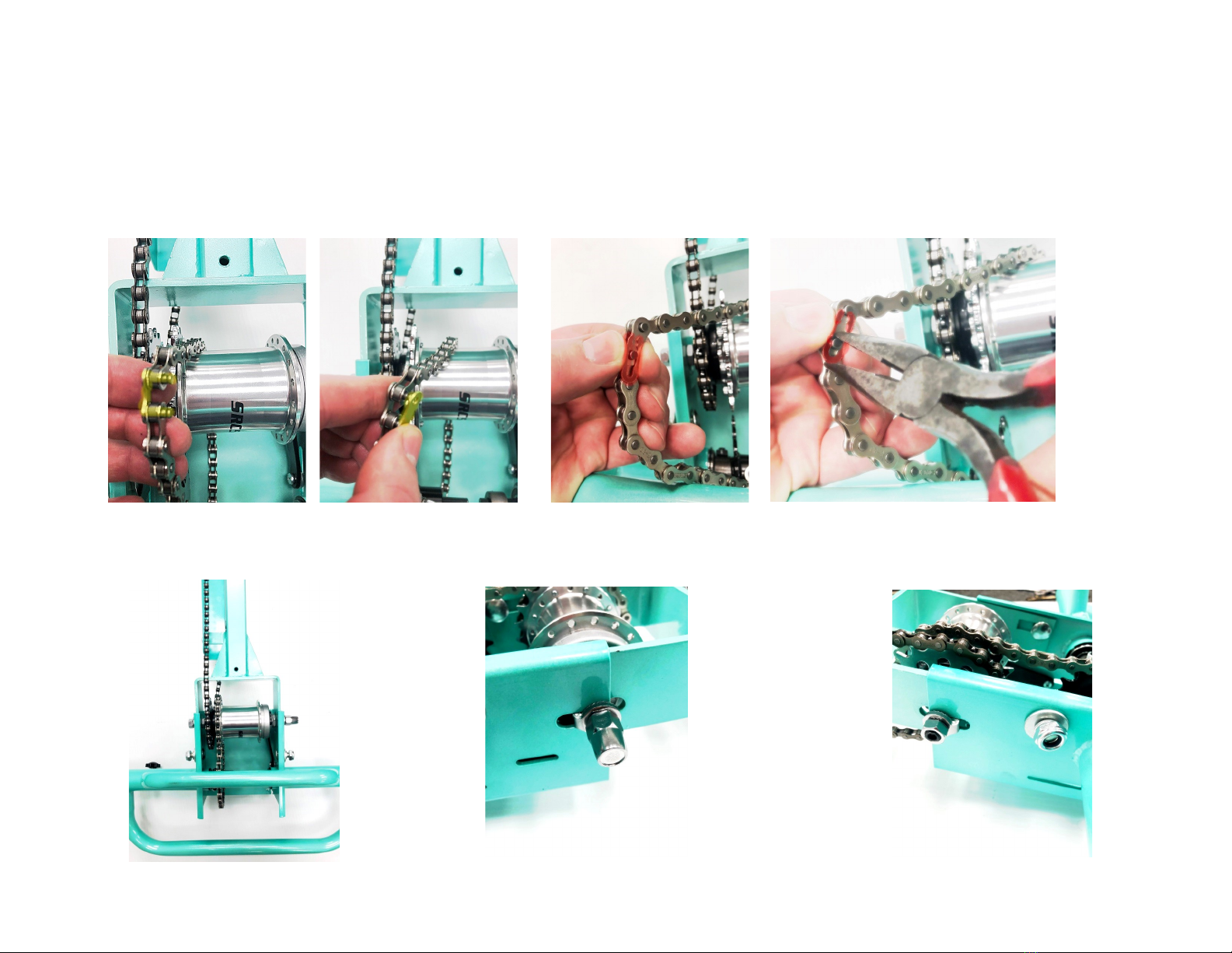
STEP 3 Continued
B. Look at the highlighted areas below. Insert the masterlink from the side that will pass the front chain. The bridge should be installed on the
opposite side from the front chain. Finally, install the clip with the rounded end facing toward the side of the chain the will be in the front of the
rotaon when pedaled. Keep in mind the trike is upside down. The idea is that pedaling should not be able to unclip the masterlink by merely
pedaling. Finally, secure the clip and masterlink with a pair of plyers securing the clip into place.
C. Loop the short chain over the right chainring on the hub (while upside down) and the chainring on the rear drive axle.
Boom of Chassis Right side of Chassis while upside down Le side of Chassis while upside down
8
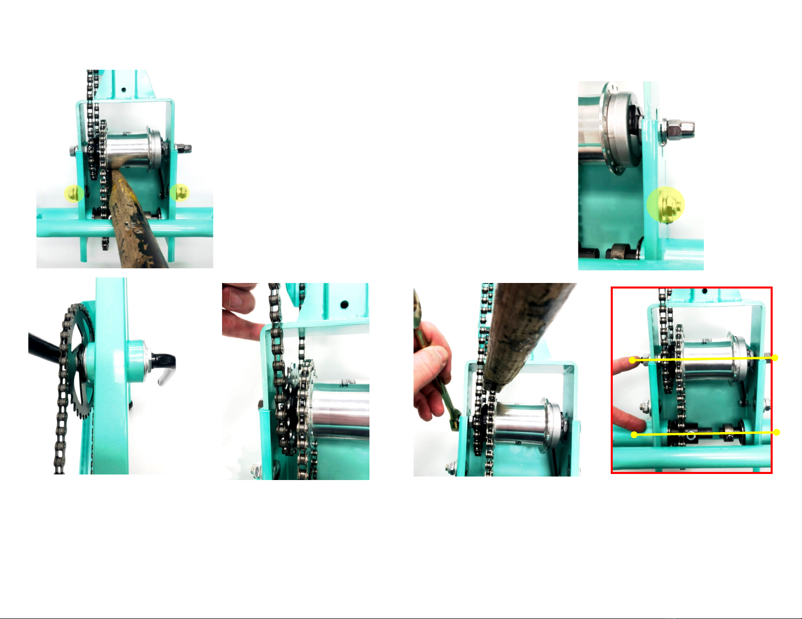
STEP 4 Chain and Chassis Adjustment
Using any sck as a lever, push the hub forward using the lever
against the tube on the rear chassis. While holding pressure against
the hub with the rear chain taught, ghten each of the carriage
bolts on the outside of the rear chassis. Tighten these two bolts as
ghtly as able by hand. These two bolts aach the two frame
pieces together.
Conrm the front chain is
looped over and around the
front chainring on the cranks.
Conrm the front chain is
looped over and around the
le chainring on the hub.
While using the lever to pull the
hub backwards, thus taking the
slack out of the front chain,
ghten the nuts on each end of
the axle equally.
IMPORTANT!
Make certain the rear drive axle
and hub axle are perfectly parallel.
Otherwise, the chains will not align
properly causing noise and
derailment.
9
STEP 5 Brake Installation
In Step 2, the brake bolt was inserted through the wall of the rear
chassis, through 2-3 washers for spacing and nally through the
brake stabilizer arm on the coaster brake. While holding the nut
from turning inside the rear chassis, use screwdriver to complete
ghten the brake arm, the last of the bolts on the rear chassis.
STEP 6 Wheel Installation
front
Slide the front wheel into the dropouts of the fork. Note the rotaon direcon arrow on
the side of the re and install the wheel accordingly. The washers are to be installed on the
outside of the dropouts as shown in the photo above. Tighten the front wheel with equal
turns on the le and right axle nut unl completely ght, while making certain the center of
the re follows the center of the front fork.
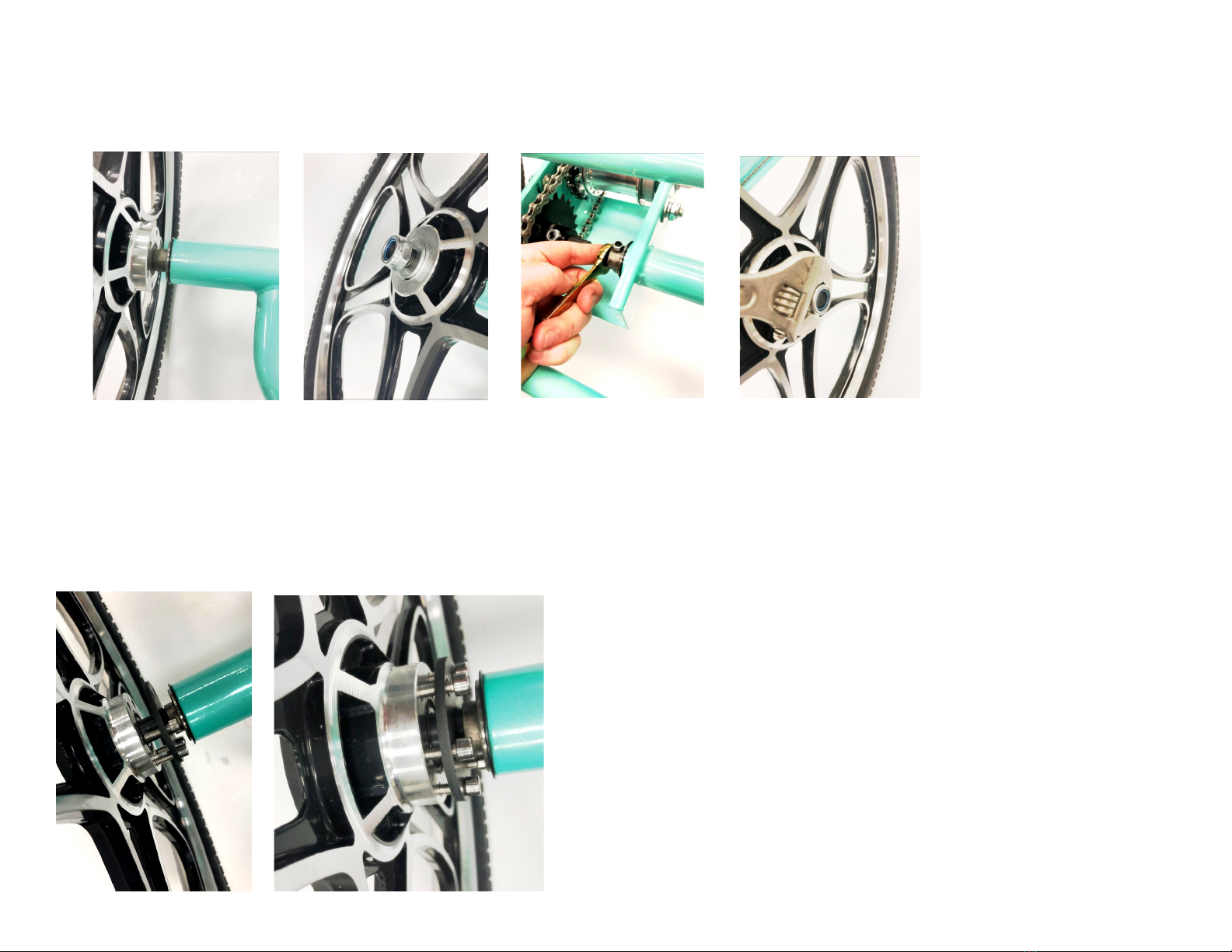
10
As illustrated above, locate the rear wheel without the 6 Allen head bolts installed and slide it onto the le side axle, which freewheels (keeping
in mind that the trike is upside down). Install the large washer and compression nut on the outside end of the axle. While holding the inside
end of the axle from turning, ghten the compression nut unl the axle is ush with the end of the axle. Conrm the wheel rotates easily but
does not slide le to right. If it does, ghten it a lile more.
STEP 6 Continued
Rear—Left non-drive wheel
Rear—Right drive wheel
Next locate the rear wheel with the 6 Allen head bolts installed. Loosen and
remove the bolts. Slide the wheel onto the outside end of the drive axle.
Leaving approximately 1/4 inch between the mag and the drive disk on the
axle, install all 6 bolts rst nger ght by alternang to the bolt hole across
from the last installed. Aer all 6 are installed nger ght, use an Allen
wrench to completely ghten each of the 6 bolts again alternang across from
each other. Aer all 6 are snuggly ghtened, nish the wheel installaon
following the instrucons for the outside nut on the non-drive wheel above.
11
STEP 7 Seat Installation
As illustrated above, locate the seat frame, the two seat pads and the 5 Allan bolts, at washers and lock washers. First, install the pads to the
frame by sliding a lock washer and next a at washer on each bolt. Install 2 bolts on the backrest pad and 3 on the boom. Carefully thread each
of the 5 bolts in handght rst, the follow up with an Allan wrench to ghten them. DO NOT OVERTIGHTEN. OVERTIGHTENING will strip the seat
and ruin the padding.
Next, turn over the trike onto its 3 wheels right side up, slide the seat bracket at the boom over the top of the front chassis frame. Install the
two quick release bolts as shown above with the handles on the le side of the trike. If you intend to adjust the seat for dierent leg length on a
regular basis we strongly suggest you smear a generous amount of petroleum jelly (such as Vaseline) both on the square tube of the chassis and
inside the boom bracket of the seat show above on the right.
To secure the seat in a locked posion, with the handle open, turn the nut on the other end unl it is nger ght. Next, fold down the handle,
which will completely ghten the bolt.
12
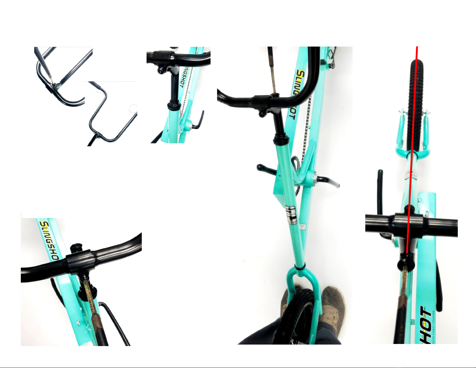
STEP 8 Handle Bar Installation
1.
3.
2.
5.
4.
Handle bars should be installed and adjusted according to your riding preference.
The bolt at the top of the handlebar stem controls the height of the bars. The bolt in
the front of the stem (show in #5) controls the angle of the handle bars. There is no
right or wrong adjustment except, you should not adjust the stem higher than any
“maximum” mark stamped into it. Also, the handlebar stem at the top should be
completely and thoroughly ghtened with the bar and fork in exact alignment as
show in #4. Be sure to ghten both Allen bolts thoroughly before aempng to ride.
13
STEP 9 Pedal and Reflector Installation
Idenfy the le and right pedals by the L and R stamped at the end of each axle. The L pedal should be install on the side without the chainring.
Use a 15 mm wrench to completely ghten both pedals. Failure to do so will cause the pedals to strip.
See the three yellow highlighted areas in the photo on the le.
1. Plug the ag pole hole you do not intend to use with the supplied
black plug.
2. Install the red reector on the rear of the seatback with an 8mm
wrench.
3. Install the hand turn bolt in the ag pole holder you intend to use with
the ag complete inserted into the holder. Tight the bolt against the
ag pole into a bind.
4. Install the white reector on the front handlebar using the black nylon
mount provide also in the box.
Final Steps: 1. Make sure all nuts, bolts and set screws are secure and wrench ght. 2. Inate res to 35 lbs.
14
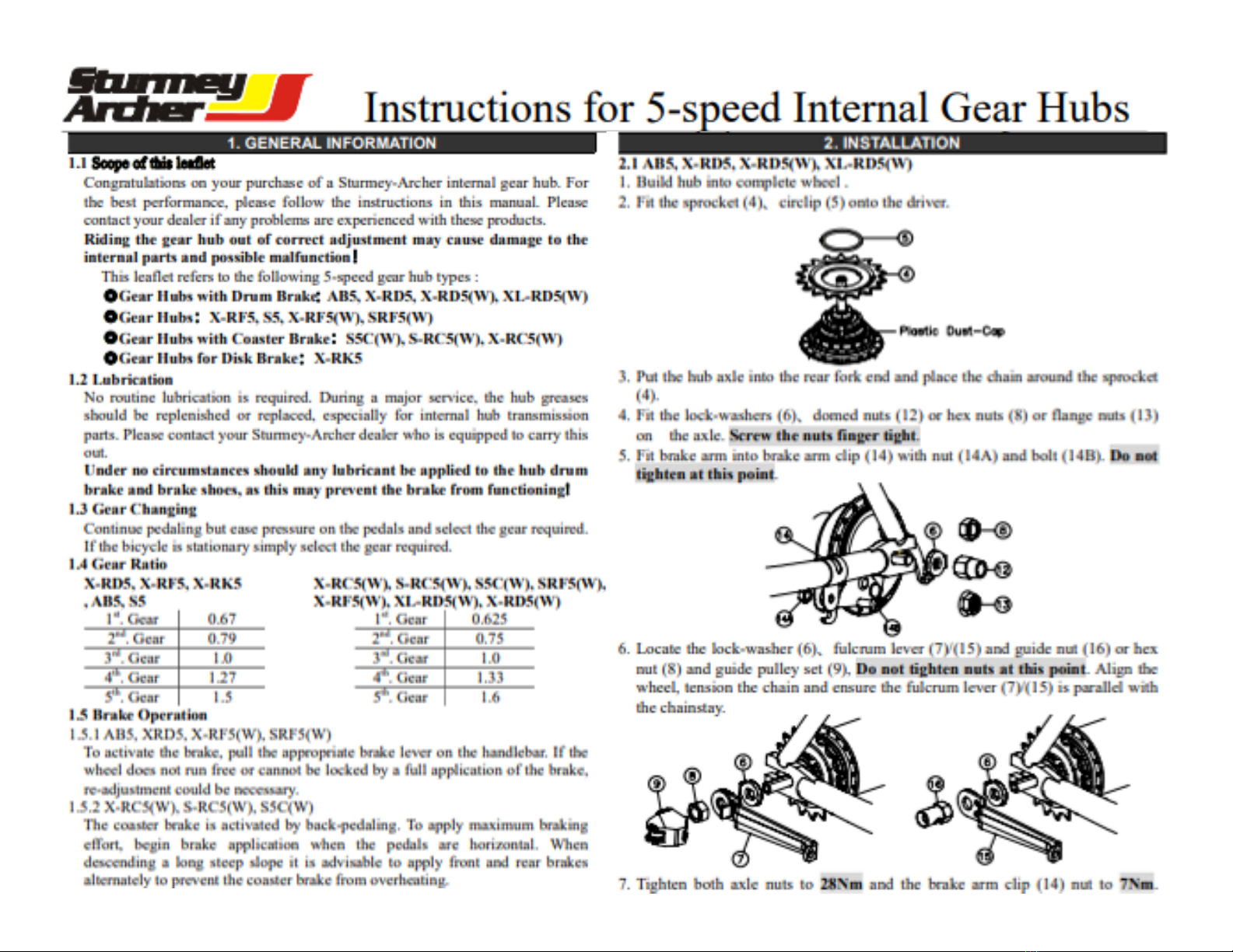
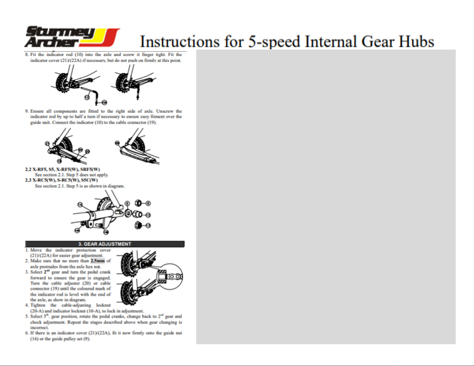
STEP 11 5 Speed Installation and Adjustment
1. 2.
3.
4.
5. 6.
7.
8.
9. 10.
11.
12.
13.

15
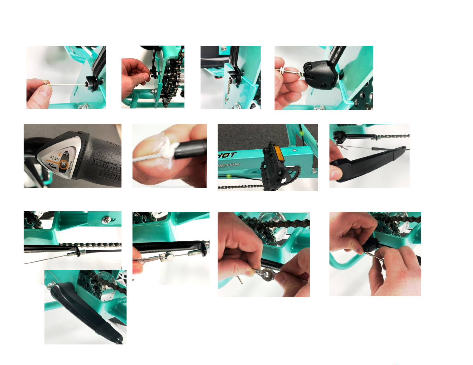
STEP 11 Continued
1. Install the indicator rod into the le side of the hub by inserng it as far as it goes and turning it clockwise unl ght. Backo 1/2 turn to
that the chain hangs as show in photo 3.
2. Pull the chain through the black pivot cap.
3. Set the shier to 5th gear.
4. Insert the inner wire into the shier housing with a lile grease applied to the inner wire as it enters the housing.
5. Insert the housing through the cable guides as you choose en route to the rear hub as shown in photo 7.
6. Slide the wire and housing through the p of the gear guide cover as shown in photo 8.
7. Slide the inner wire through the jackscrew at the end of the fulcrum lever and insert the end of the housing inside the jackscrew.
8. Slide the inner wire through the cable connector and binder bolt.
9. Adjust the cable connector on the inner wire so that when connected to the chain at the end of the indicator rod, the wire is taught in
5th gear.
10. Securely ghten the binder bolt at that posion.
11. Connect the cable connector to the indicator rod by turning it with your nger ps. Tighten the small jam nut against the end of the ca-
ble connector to prevent it from loosening.
12. Install the black gear guide cover over the fulcrum lever as shown in photo 13.
Note: The follow page are instrucons from the manufacturer of the 5 speed shiing system.
CAUTION—1. Make sure all nuts, bolts and set screws are secure and wrench ght. 2. Inate res to 35 lbs.
Have Questions? Call 1-800-765-7370 ext 3 for Assistance
©2021 Internaonal Surrey Company . All rights reserved. No poron of this manual or any artwork, photographs or descripons herein may be reproduced in any shape or
form without the express wrien consent of Internaonal Surrey Company Ltd. Diagrams within this manual may not be drawn proporonally. Due to connuing
improvements, actual product may dier form the product described herein. Tools required for assembly and service are not included.
16
17
RIDING SAFETY
• When riding obey the same road laws as all other road vehicles, including giving way to pedestrians,
and stopping at red lights and stop signs. For further information, contact the Road Traffic Authority
in your State.
• Ride predictably and in a straight line. Never ride against traffic.
• Use correct hand signals to indicate turning or stopping.
• Ride defensively. To other road users, you may be hard to see.
• Concentrate on the path ahead. Avoid pot holes, gravel, wet road markings, oil, curbs,
speed bumps, drain grates and other obstacles.
• Cross train tracks at a 90 degree angle or walk your cycle across.
• Expect the unexpected such as opening car doors or cars backing out of concealed driveways.
• Be extra careful at intersections and when preparing to pass other vehicles.
• Familiarize yourself with all the cycle’s features. Practice gear shifts, braking, and the use
of toe clips and straps, if installed.
• If you are wearing loose pants, use leg clips or elastic bands to prevent them from being caught in
the chain.
• Wear proper riding attire and avoid open toe shoes.
• Don’t carry packages or passengers that will interfere with your visibility or control of the cycle.
• Don’t use items that may restrict your hearing.
• Do not lock up the brakes. When braking, always apply the rear brake first, then the
front. The front brake is more powerful and if it is not correctly applied, you may lose
control and fall.
• Maintain a comfortable stopping distance from all other riders, vehicles and objects.

18
RIDING SAFETY
General Rules
• When riding obey the same road laws as all other road vehicles, including giving
way to pedestrians, and stopping at red lights and stop signs. For further
information, contact the Road Traffic Authority in your State.
• Ride predictably and in a straight line. Never ride against traffic.
• Use correct hand signals to indicate turning or stopping.
• Ride defensively. To other road users, you may be hard to see.
• Concentrate on the path ahead. Avoid pot holes, gravel, wet road
markings, oil, curbs, speed bumps, drain grates and other obstacles.
• Cross train tracks at a 90 degree angle or walk your Cycle across.
• Expect the unexpected such as opening car doors or cars backing out of concealed
driveways.
• Be extra careful at intersections and when preparing to pass other vehicles.
• Familiarize yourself with all the Cycle’s features. Practice gear shifts,
braking, and the use of toe clips and straps, if installed.
• If you are wearing loose pants, use leg clips or elastic bands to prevent them from
being caught in the chain.
• Wear proper riding attire and avoid open toe shoes.
• Don’t carry packages or passengers that will interfere with your visibility or control of
the Cycle.
• Don’t use items that may restrict your hearing.
• Do not lock up the brakes. When braking, always apply the rear
brake first, then the front. The front brake is more powerful and if
it is not correctly applied, you may lose control and fall.
• Maintain a comfortable stopping distance from all other riders,
vehicles and objects.
• Safe braking distances and forces are subject to the prevailing
weather conditions.
Be sure to understand the following common sense safeguards for operating your
Cycle, to reduce the risk of personal injury. Parents of minor riders have an obligation to be sure their children un-
derstand these safeguards.
• Be sure you understand all the operations of your Cycle.
• Be sure all equipment is properly adjusted, especially your wheels, steering and brakes.
• Obey traffic laws. Cyclists are subject to the same rules as motorists. Know and obey all motor-vehicle, cycle
and traffic laws.
• Use common sense. Slow down for intersections. Do not erratically weave in and out of motor traffic. Watch for
parked cars suddenly pulling out, or their doors opening.
• Avoid heavy motor traffic.
• Never carry more persons than your Cycle is designed to carry by the manufacturer.
• Make use of safety accessories and clothing. Wear bright or light colored clothing, or a vest with reflectors,
especially at night. Wear shoes and a helmet.
• Always ride defensively. While you may be legally right, in a contest between an auto and your Cycle, the car
will come out first.
• Be especially cautious with downhill braking. With very steep downgrades, it may be impossible to stop your
Cycle in a necessary distance although the braking system meets the highest standards. To avoid possible
injury, dismount and walk your Cycle (use the brakes) to the bottom of the grade, if you do not feel secure
enough, especially on wet, muddy or gravel roads.
• Do not stunt ride. Do not use the Cycle for stunt or acrobatic riding, ramp jumping or similar activities.
Warning: Bad weather requires increased breaking distance.
On the road with wet, snowy or icy weather conditions, your brakes cannot stop you as quickly as in
clement weather conditions. Special precautions must be taken to ensure safe stopping or slowing, and
reduce the risk of personal injury. No matter how well your brake system functions, it is your
responsibility to exercise special care in such adverse situations. Ride slowly. Be more alert. Apply your
brakes sooner than you would under dry conditions.
Warning: Special precautions for night riding. Be sure your Cycle has reflectors or lights required
by law on wheels, pedals, front and back. Be sure reflectors are properly adjusted and clean. State or
local laws may require that you equip your Cycle with a light system in addition to the reflectors. Wear
special reflective clothing or tapes. Reflective clothing as well as tapes for sleeves, backs and pants are
available at cycle stores almost everywhere. Avoid cycling on dark, narrow roads. Never allow chil-
dren to ride alone at night.

19
RULES FOR CHILDREN
To avoid accidents, teach children good riding skills with an empha-
sis on safety from an early age. Children should be supervised by
an adult.
• Many states require that children wear a helmet while cycling.
Always wear a properly fitted helmet.
• Do not play in driveways or the road.
• Do not ride on busy streets.
• Do not ride at night.
• Obey all the traffic laws, especially stop signs and red lights.
• Be aware of other road vehicles behind and nearby.
• Before entering a street: Stop, look left, right, and left again for
traffic. If there’s no traffic, proceed into the roadway.
• If riding downhill, be extra careful. Slow down using the brakes
and maintain control of the steering.
• Never take your hands off the handlebars, or your feet off the
pedals when riding downhill.
• The Consumer Protection Safety Commission advises that the
riding of small wheel diameter cycles at excessive speeds can
lead to instability and is not recommended.
• Children should be made aware of all possible riding hazards
and correct riding behavior before they take to the streets.
• Do not leave it up to trial and error.
Safety is everything! Ride sensibly!
On the cycle the person steering bears direct responsibility for him/
herself and all other passengers. Ride carefully, anticipating problems,
and avoid sudden maneuvers such as unexpected fast turns and
unnecessary sharp braking.
Wet Weather
• In wet weather you need to take extra care.
• Brake earlier, you will take a longer distance to stop.
• Decrease your riding speed, avoid sudden braking and take corners with
additional caution.
• Be more visible on the road.
• Wear reflective clothing and use safety lights.
• Pot holes and slippery surfaces such as line markings and train tracks all
become more hazardous when wet.
Night Riding
IT IS RECOMMENDED TO NOT RIDE AT NIGHT
Check your local laws regarding night riding; Many areas require the use of
lights for night riding in addition to a full set of CPSC compatible reflectors.
International Surrey Company recommends you do not ride at night.
However, if you do:
• Ensure cycle is equipped with a full set of correctly positioned and clean
reflectors.
• Use a properly functioning lighting set comprising of a white front lamp
and a red rear lamp.
• If using battery powered lights, make sure batteries are well charged.
• Some rear lights available have a flashing mechanism which enhances
visibility.
• Wear reflective and light colored clothing.
• Ride at night only if necessary. Slow down and use familiar roads with
street lighting, if possible.
Table of contents


