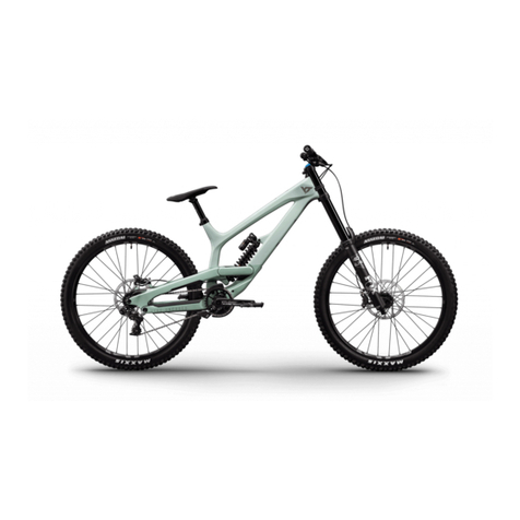
YT Industries TUES MKIII User manual

Lager: demontage – wartung – Montage
Bearings: Removal – Service – Installation
Roulements: Démontage – Entretien – Installation
rTFM
®

2 yt
grease
grease
grease
grease
grease
grease
grease
grease
grease
12 nm Loctite
12 nm Loctite
12 nm Loctite
8 nm Loctite
17 nm
15 nm
20 nm
5 nm Loctite
5 nm Loctite
Loctite
grease
Loctite
MAINPIVOT
HORST-LINK
LINK
(Drehpunkte des
Umlenkhebels)
(Drehpunkt der
Kettenstrebe)
(Drehpunkt der
Ausfallenden des
Rahmens)

yt 3
grease
grease
grease
grease
grease
grease
grease
grease
grease
12 nm Loctite
12 nm Loctite
12 nm Loctite
8 nm Loctite
17 nm
15 nm
20 nm
5 nm Loctite
5 nm Loctite
Loctite
grease
Loctite
DE
KEIN
STANDARD
RIDE
KEINE
STANDARD
LÖSUNG
TUES MKIII
LAGERDEMONTAGE – WARTUNG – LAGERMONTAGE
ACHTUNG! MONTIERST DU DIE
ACHSE FALSCH, BESTEHT DIE
GEFAHR, DASS DU BEIM FAHREN
DEN RAHMEN BESCHÄDIGST.
WENN DU DIR NICHT SICHER
BIST, ÜBERLASSE DIE MONTAGE
IN JEDEM FALL EINER FACH-
WERKSTATT!
NOCH FRAGEN? DU
ERREICHST UNS ÜBER:
SERVICE@YT-INDUSTRIES.COM
IM HINTERBAU DES TUES FINDEST DU DREI ACHSEN, DIE MIT
EINEM SPREIZ-KONUS MONTIERT SIND.
Welche das sind, haben wir in der Zeichnung markiert.
Die Achsen folgen technisch dem selben Prinzip: Zuerst
wird die Achse eingeschraubt, danach der dazugehörige
Spreiz-Konus. Dieses Manual erklärt Dir, wie die Wartung
dieser Drehpunkte funktioniert.

4 yt
WARTUNG
LINK
Löse die Sicherungsschrauben der Achsen-
klemmung des Umlenkhebels mit einem
4 mm Inbusschlüssel.
Entferne die Sicherungsschraube und den
Konus der Achse. Sollte der Konus festsitzen,
nutze einen 5 mm Inbusschlüssel, um ihn
herauszuholen.
Löse und entferne den Dämpferbolzen an der
vorderen Dämpferaufnahme.
Löse und entferne den Dämpferbolzen an der
hinteren Dämpferaufnahme.
Entferne den Dämpfer.
Jetzt kannst Du die obere Achse des Um-
lenkhebels mit einem 6 mm Inbusschlüssel
entfernen.
1.1 1.2 1.3
1.4 1.5 1.6

yt 5
DE
WARTUNG
LINK
Entferne die Achse des Umlenkhebels am
Hauptrahmen mit einem 8 mm Inbusschlüssel.
Fette die Lagerabdeckungen neu, um das Ein-
dringen von Wasser und Schmutz in die Ku-
gellager zu erschweren. Ein leichter Fettfi lm
auf den Achsen und hinter den Abdeckungen
reicht hierfür schon aus.
Entnehme beide Seiten des Umlenkhebels, um
an die Lagerung zu gelangen.
Versehe den Umlenkhebel auf der Nicht-An-
triebsseite mit den Lagerabdeckungen und
Achsen. Führe ihn anschließend in die Dreh-
punkte am Rahmen ein.
Entnehme die Lagerabdeckungen und befreie
sie von Schmutz und alten Schmierstoffen.
Platziere die Lagerabdeckungen der An-
triebsseite und verschraube den Umlenkhe-
bel auf dieser Seite. Verwende hierbei einen
Schraubensicherungskleber (mittelfest).
1.7
1.10
1.8
1.11
1.9
1.12

6 yt
Die Achsen sind mit einem Spreiz-Konus ge-
sichert, damit sie sich nicht lösen. Bestreiche
die Konen mit Schraubensicherungskleber
(mittelfest).
Ziehe die Schrauben so lange an, bis die Umlenk-
hebel parallel an den Lagerpunkten anliegen.
Ziehe sie anschließend einzeln mit einem
Drehmomentschlüssel an (8mm Inbus: 20 Nm;
6mm Inbus: 15 Nm).
Verschraube die Konen in den Achsen und
ziehe sie anschließend mit einem Drehmo-
ment von 5 Nm an.
ACHTUNG! Arbeite beim Festziehen
mit zwei Werkzeugen gleichzeitig
und parallel. Dadurch verhinderst
Du, dass sich die Umlenkhebel ver-
kanten, verspannen oder Bauteile
beschädigt werden.
WARTUNG
LINK
1.13
1.14 1.15

WARTUNG
DE
ACHTUNG! Bitte leicht fetten
und Schraubensicherungskleber
verwenden!
Jetzt demontierst Du die Achse des Dreh-
punktes der Kettenstrebe (Mainpivot).
Entferne dafür zuerst die Achsenklemmung
mit einem 5 mm Inbusschlüssel.
Befreie die Lagerabdeckungen von alten
Schmierstoffen und Schmutz. Montiere sie
wieder in umgekehrter Abfolge. Benetze dabei
die Achse, Lager und Abdeckungen mit einem
leichten Fettfi lm.
Anschließend demontierst Du die Achse mit
einem 6 mm Inbusschlüssel.
Platziere die Kettenstrebe über dem Drehpunkt.
Verschraube die Achse mit einem 6 mm Inbus-
schlüssel und einem Anzugsmoment von
17 Nm mit Hauptrahmen und Kettenstrebe.
Nun kannst Du die Kettenstrebe ganz einfach
nach hinten von dem Lagerpunkt ziehen.
Achte dabei darauf, die Lagerabdeckungen
nicht zu verlieren!
Danach sicherst Du die Achse mit dem
Spreiz-Konus gegen ungewolltes Lösen. Be-
achte dabei das Anzugsmoment von 8 Nm.
MAINPIVOT
2.1
2.4
2.2
2.5
2.3
2.6

8 yt
Setze die Lagerabdeckungen auf die Lager,
bevor Du Kettenstrebe und Sitzstrebe wieder
miteinander montierst.
Verschraube nun die Achsen wieder mitein-
ander. Auch hier gilt: Achsen leicht fetten und
Schrauben mit Sicherungskleber versehen.
Für die Wartung der Drehpunkte an den Aus-
fallenden des Rahmens (Horst-Link) löst Du
zuerst die Achsen auf beiden Seiten mit ei-
nem 5 mm und einem 6 mm Inbusschlüssel.
Hebe die Sitzstrebe aus der Kettenstrebe.
Achte darauf, die Lagerabdeckungen nicht zu
verlieren! Diese befi nden sich innerhalb der
Drehpunkte auf den Kugellagern.
Auch hier gilt wieder: Drehpunkte von alten
Schmierstoffen und Schmutz befreien, frisch
fetten und wieder zusammenbauen.
Bitte beachte hier das Anzugsmoment von
12 Nm.
WARTUNG
HORST-LINK
3.1 3.2 3.3
3.4 3.5 3.6

yt 9
yt
9
IT´S
DONE
DE

10 yt
grease
grease
grease
grease
grease
grease
grease
grease
grease
12 nm Loctite
12 nm Loctite
12 nm Loctite
8 nm Loctite
17 nm
15 nm
20 nm
5 nm Loctite
5 nm Loctite
Loctite
grease
Loctite
MAINPIVOT
HORST-LINK
LINK
(rocker link
pivot points)
(pivot point of the
chainstays)
(pivot point of
the seatstays)

yt 11
grease
grease
grease
grease
grease
grease
grease
grease
grease
12 nm Loctite
12 nm Loctite
12 nm Loctite
8 nm Loctite
17 nm
15 nm
20 nm
5 nm Loctite
5 nm Loctite
Loctite
grease
Loctite
EN
TUES MKIII
BEARING REMOVAL – SERVICE – BEARING INSTALLATION
IN THE REAR OF THE TUES YOU WILL FIND THREE AXLES
THAT ARE FITTED WITH AN EXPANDING CONE.
For your convenience, these are indicated in the drawing
to the left.
These axles all work the same way: fi rst, the axle is screwed
in, then the expanding cone. This manual describes how to
service these pivot points.
NOT A
STANDARD
BIKE
NOT A
STANDARD
SOLUTION WARNING! IF YOU DO NOT
MOUNT THE AXLE IN THE COR-
RECT WAY, YOU RUN THE RISK
OF DAMAGING YOUR FRAME
WHILE RIDING. IF YOU ARE NOT
SURE, LEAVE THE ASSEMBLY TO
A QUALIFIED SPECIALIST WORK-
SHOP.
IF THERE ARE ANY QUESTIONS,
WRITE TO:
SERVICE@YT-INDUSTRIES.COM

12 yt
SERVICE
LINK
Release the axle locking bolts of the rocker
link with a 4mm allen key.
Remove the locking bolts and the expanding
cones from the axle. If the expanding cone is
stuck, use a 5mm allen key to work it loose.
Unscrew and remove the bolt at the forward shock
mount.
Unscrew and remove the bolt at the rear shock
mount.
Remove the damper.
You can now remove the top axle from the
rocker link with a 6mm allen key.
1.1 1.2 1.3
1.4 1.5 1.6

yt 13
EN
SERVICE
LINK
Remove the lower rocker link axle from the
main frame with an 8mm allen key.
Apply fresh grease to the bearing covers in
order to prevent dirt and water ingestion. A
light coating of grease on the axle and bearing
covers is enough.
Remove both rocker link plates in order to
access the bearings.
Install the axles and bearing covers in the
non-drive side rocker link plate, then guide the
whole assembly into the frame pivot points.
Remove the bearing covers and clean off any
dirt and grease.
Install the drive-side bearing covers and
screw the axles into the rocker link plate on
this side. Apply a medium strength thread
lock here.
1.7
1.10
1.8
1.11
1.9
1.12

14 yt
The axles are secured with an expanding cone
to avoid them coming loose. Apply medium
strength thread lock to the cones before in-
stalling them.
Screw the axles in until the rocker link plates are
parallel to the pivot points. Then use a torque
key to tighten both axles to spec (8mm allen:
20nm, 6mm allen: 15nm).
Screw the expanding cones into the axles and
tighten them to 5nm using a torque key.
ATTENTION! Work with two tools
in parallel and at the same time,
to avoid tilting or putting tension
on the rocker link plates or causing
damage to other components.
SERVICE
LINK
1.13
1.14 1.15

SERVICE
EN
ATTENTION! Apply light grease and
use thread lock!
Now remove the axle from the main pivot
point (chainstay-frame). First, remove the
locking bolt and the spreading cone with a
5mm allen key.
Clean the bearing covers, removing any
dirt and grease. Simply reverse the order
to reinstall them. Apply a light coating of
grease to the covers, axles, and bearings.
Remove the axle itself with a 6mm allen key.
Place the chainstays and the bearing covers
on the pivot point. Tighten the frame-chain-
stay bolt to 17nm using a 6mm allen key.
You can now simply slide the chainstays off
the main pivot point from behind. Take care
not to lose the bearing covers!
Secure the axle with the locking bolt and ex-
panding cone to avoid it coming loose. The
locking bolt should be torqued to 8nm.
MAINPIVOT
2.1
2.4
2.2
2.5
2.3
2.6

16 yt
Place the bearing covers over the bearings
before sliding the seatstays and chainstays
together again.
Now you just need to screw the axles togeth-
er again. Also valid here: apply a light coat of
grease to the axles and use thread lock on
the bolts.
To service the drop-out pivot points (Horst-
Link) you start by removing the axles from
both sides using a 5mm and a 6mm allen key.
Lift the seatstays out of the chainstays. Take
care not to lose the bearing covers! These are
found on the inside of the pivot points, cover-
ing the bearings.
Also valid here: clean the pivot points from
dirt and old grease, re-grease and reassemble.
The Horst-Link axles should be torqued to
12nm.
SERVICE
HORST-LINK
3.1 3.2 3.3
3.4 3.5 3.6

yt 17
yt
17
IT
IT
´
S
DONE
DONE
EN

18 yt
grease
grease
grease
grease
grease
grease
grease
grease
grease
12 nm Loctite
12 nm Loctite
12 nm Loctite
8 nm Loctite
17 nm
15 nm
20 nm
5 nm Loctite
5 nm Loctite
Loctite
grease
Loctite
PIVOT PRINCIPAL
HORST-LINK
LINK
(points pivot
du basculeur)
(point de pivot
des bases)
(point de pivot
des haubans)

yt 19
grease
grease
grease
grease
grease
grease
grease
grease
grease
12 nm Loctite
12 nm Loctite
12 nm Loctite
8 nm Loctite
17 nm
15 nm
20 nm
5 nm Loctite
5 nm Loctite
Loctite
grease
Loctite
FR
TUES MKIII
DÉMONTAGE – ENTRETIEN – INSTALLATION DES ROULEMENTS
A L’ARRIÈRE DU TUES TU TROUVERAS TROIS AXES ÉQUIPÉS
D’UN CÔNE D’EXPANSION.
Ces axes sont désignés dans le dessin à gauche.
Ces axes fonctionnent tous de la même manière: d’abord,
l’axe est vissé, puis le cône d’expansion. Ce manuel décrit
comment entretenir ces points de pivot.
D’AUTRES QUESTIONS?
TU PEUX NOUS JOINDRE AU:
SERVICE@YT-INDUSTRIES.COM
PAS UN
VÉLO
NORMAL
PAS UNE
SOLUTION
NORMALE ATTENTION ! SI TU INSTALLES
CES AXES DE LA MAUVAISE
FAÇON, TU RISQUES
D’ENDOMMAGER TON CADRE AU
ROULAGE. SI TU N’ES PAS SÛR
DE POUVOIR EXÉCUTER CES
TRAVAUX EN BONNE ET DUE
FORME, TOURNE-TOI VERS UN
ATELIER SPÉCIALISÉ.

20 yt
ENTRETIEN
LINK
Dévisser les boulons de verrouillage du bas-
culeur avec une clé allen de 4mm.
Enlever les boulons de verrouillage et les cônes
d’expansion de l’axe. Si le cône d’expansion
est coincé, il faut le décoincer à l’aide d’une
clé allen de 5mm.
Dévisser et démonter le boulon à l’avant de l’amor-
tisseur.
Dévisser et démonter le boulon à l’arrière de l’amor-
tisseur.
Enlever l’amortisseur.
Tu peux maintenant enlever l’axe supérieur du
basculeur avec une clé allen de 6mm.
1.1 1.2 1.3
1.4 1.5 1.6
Table of contents
Languages:
Other YT Industries Bicycle manuals

YT Industries
YT Industries TUES FR User manual

YT Industries
YT Industries Jeffsy Primus User manual

YT Industries
YT Industries rtfm. User manual

YT Industries
YT Industries RTFM JEFFSY Instruction sheet

YT Industries
YT Industries DIRTLOVE User manual

YT Industries
YT Industries Jeffsy User manual
YT Industries
YT Industries TUES User manual

YT Industries
YT Industries TUES 27 Carbon User manual

YT Industries
YT Industries Capra MX CORE 3 Instruction sheet