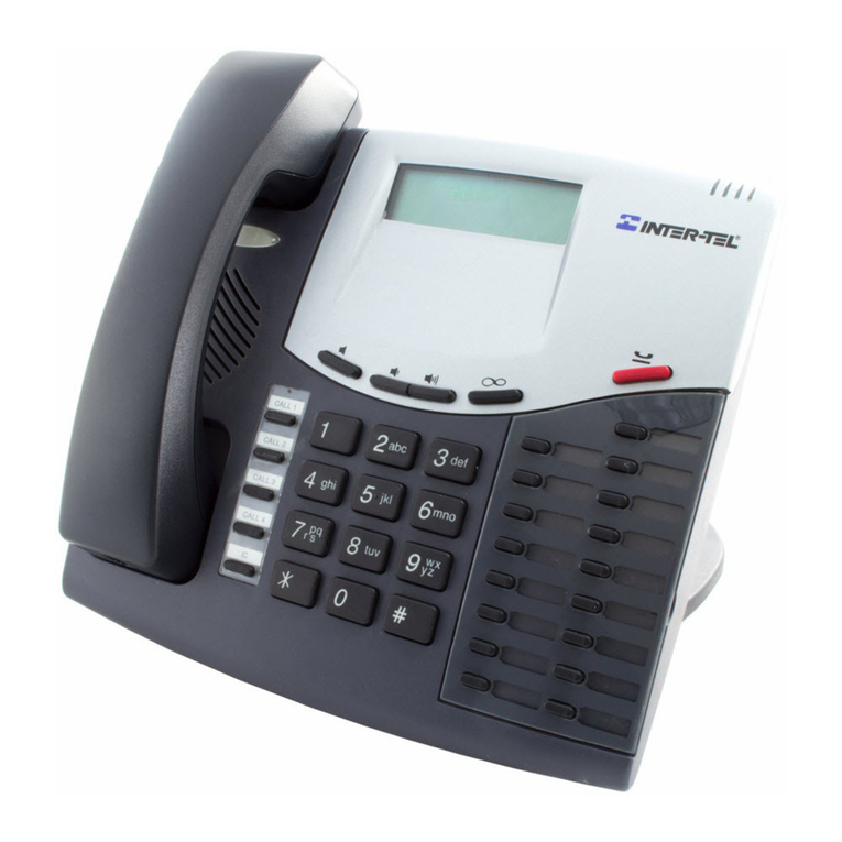
intertel IMX 256 Manual

I
N
T
EGR
AT
ED
TM
lMWGMX256
\
INSTALLATION AND FIELD
MAINTENANCE MANUAL
Part No. 440.8074
Issue
1,
November 1994

lMwGMX256
INSTALLATION AND FIELD
MAINTENANCE MANUAL
NOTICE
IMX
81
GMX COMBINED INTO ONE MANUAL
With the new 1995 North American Numbering Plan software releases, the
Ih4X
256 and GMX-256 products are iden-
tical except for the station instruments that can be installed on them. To provide better service, condense reference
materials, streamline training, and facilitate technical support, the installation manuals for the two systems have been
combined into one generic manual.
When using this combined manual to help sell, install, or service a particular system, be aware that not all of the station
instruments described in this manual are available on both products. Listed below are the station instruments that can
be installed on each product.
IMX 256 Station Instruments GMX-256 Station Instruments
lDigital
Keyseta
(including
PCDPMs
62
MDPMs)
lIMX AIM
Keysets
(including “dual-circuit”
keysets)
l
lMX
(non-AIM)
Keysets
0
GX
Keysets
l Attendant Computer Consoles
0
Digital
DSS/BLF
Units
0
IMX
DSS/BLF
Units
0
GX
DSS/BLF
Units
l Enhanced Single-Line Sets
(ESLSs)
0IMX
Single-Line Instruments
(SLls)
0
Single-Line DTMF Sets
0
Inter-Tel/DVK
Keysets
0
Gh42C
Keysets
0
GX
Keysets
l Attendant Computer Consoles
0
Inter-Tel/DVK
DSS/BLF
Units
0
GhIX
DSS/BLF
Units
0
GX
DSS/BLF
Units
0
GMX Single-Line Instruments
(SLIs)
.
GXSLIs
0
Single-Line DTMF Sets
Part No. 440.8074
Issue 1, November 1994

Part Number
440.8074
I
N
T
E
G
RA
T
ED
TM
lMwGMX256
INSTALLATION AND
FIELD MAINTENANCE
MANUAL
Issue 1, November
1994
@Inter-Tel Integrated Systems, inc. 1994 Printed in USA

IMX
256 ISSUE 2
-
INDEX OF NEW FEATURES
For those individuals who are already familiar with the Issue 1 manuals for the
lMX
256 and GMX-256 Systems, the
following new items are documented in this combination manual. For complete information on each item, refer to the
page numbers following the brief explanation. Also, throughout the manual, %hange bars” like the one at the right
have been placed in the margins to indicate any new or revised information since the original manuals.
I
IMX
And GMX Combined Into One Manual
with
the new 1995 North American Numbering Plan software releases, the IMX 256 and GMX-256 products are
identical except for the station instruments that can be installed on them. To provide better service, condense refer-
ence materials, streamline training, and facilitate technical support, the installation manuals for the two systems
have been combined into one generic manual. When using this combined manual to help sell, install, or service a
particular system, be aware that not all of the station instruments described in this manual are available on both
products. See page 2-2 for a list of the station instruments that can be installed on each product.
North American Numbering Plan
(NANP)
The growth of telecommunications services has created an increasing demand for more telephone
numbers.
To
meet the demand,
Bellcore
has prepared a long-range North American Numbering Plan (NANP) to provide addi-
tional telephone numbers. The plan expands the capacity of the current numbering system by making area and
office codes interchangeable. That is, numbering patterns formerly reserved for office codes can be used as new
area codes and office codes within existing area codes can have the same pattern as other area codes. This version
of software supports the new numbering plan. See pages
4-28
and 5-90.
Home And Local Area Codes
In many areas, the telephone company has created call-cost arrangements that refer to “home” and “local” area
codes. The home area code is the area code within which the system resides. The local area codes are additional
area codes that, when called, use the local or toll local call-cost rate instead of the long distance rate. Up to three
local area codes can be programmed and then extended within toll restriction progxamming to provide proper call
costing. See pages 4-29 and 5-171.
Loop Start
‘Ikunk
Glare Protection
During a “glare” connection, the software now allows the incoming call to remain connected, while still protecting
against possible toll fraud. See pages 2-14 and
5-68.
Station Exchange
This programmable station feature allows a station user to exchange the extension numbers of two station circuits.
This swaps the database and user programmed features of the extension numbers between two station circuits
without the need for database programmin
g.
The circuit number of the station locations are unchanged, but the
extension numbers are changed. See pages 4-99 and 5-31.
Digital Cards, Diil
Keysets,
and
Diiti
DSWBLF
Units
The IMX 256 System can now support the digital station instruments originally designed for the Inter-Tel Axxess
System. See pages
2-2,2-g,
2-12,2-13,2-21
to
2-27,2-33,2-34,2-44,3-7,3-22,3-28,3-29,347,3-48,
3-62 to
3-70,3-90,3-91,4-21,4-40,4-50,5-24,547,5-135,6-3,7-1,
and 7-3.
All digital keysets utilize DSP shared resources for speakerphones, and Executive Digital Keysets have enhanced
displays. See pages 2-22,440, and 4-41.
APC Data Port Module (PCDPM) must be installed on digital keysets to provide the secondary voice path needed
for the
OIWA
feature. See pages
2-23,3-66,
and 4-61.
A
customer-provided, modem-equipped data device may be attached to any digital keyset with a PC Data
Port
Module (PCDPM) and a Modem Data Port module (MDPM) installed. See pages
2-23,3-70,
and 4-101.
Feature And Speed-Dial Keys On
DSWBLF
Units
DSS/BLF Units can have feature keys or system speed-dial keys programmed in their keymaps. See pages 4-50,
4-87, and 5-50.
Page v

INDEX OF NEW FEATURES (continued)
Keyset
“Hot” Dial Pad Keys
There is a system-wide option that, if enabled, allows keyset users to dial line access codes and feature codes with-
out lifting the handset or pressing the SPKR or SPCL key. This programmable feature is called “hot dial pad” to
indicate that the dial pad keys are always activated. See pages
44,4-42,
and 5-68.
Private Intercom Call Override
If a keyset station has the Private Intercom Override feature enabled, the user can place a
handsfree
call by press-
ing
l
or
#
when calling a keyset station that has handsfree mode disabled. See pages
4-56,5-30,
and 5-52.
%ilent”
u
Tone Selection
When
setting the ring tone on a keyset, the keyset user can enter 0 to disable ring tones. See page 4-48.
Toll
Sew&y
Feat=
Set
The
Extended
software package now includes the following Toll Security features:
Weekly Toll Limits:
When enabled, the weekly toll limit feature keeps track of the accumulated call cost for spe-
cified types of toll calls. The feature can monitor 7- and
lOdigit
toll calls and/or operator-assisted/international
calls. Alarm messages have been added for toll limit management. See pages
4-10,4-30,4-62,4-63,4-83,
4-1X2,4-125,5-97,
and 6-8.
Inter-Tel
Services: The weekly toll limit feature can only be enabled by Inter-Tel Services. See page 6-41.
Enhanced DISA
Security
Codes: DISA security codes can be 4-7 digits long. ADISA caller will have only three
opportunities to enter a valid security code. If the caller fails three times, the failure will generate a system alarm
and that trunk will be inoperable for five minutes. See pages
4-38,5-111,5-115,
and 6-8.
DISA Toll Restriction:
DISA lines can be given day and/or night mode toll restrictions like those for individual
stations (except LCR-Only). See pages
4-38,5-106,5-111,
and 5-116.
SMDR Blocked DISA
Calls
Option:
A programming flag has been added to SMDR that allows blocked DISA
calls to appear in the Sh4DR report. See pages
4-38,4-123,
and 4-124.
DISA And Hunt Group
Information
In
SMDA Summary Reports
DISAcall
information has been added to the System Summary report and a new Hunt Croup option has been added
to the Summary Report. See pages
4-38,4-115,4-118,
and 5-140.
End-Of-Dialing Digit Suppression
Display and Redial: A system
programmin g flag allows the programmer to specify whether all dialed digits or
just the digits that make up the valid call are displayed and stored in the redial buffer. If desired, the “extra” digits
used for dial-up banking machine, voice mail, automated attendant, or other purposes
canbe
suppressed. Suppres-
sing the extra digits prevents entries, such as PIN numbers and other codes, from being displayed when they are
dialed. See pages 4-93 and 5-69.
SMDRReportsz
A programming flag has been added to the
SMDRreport
programmingprompts that allows you
to specify whether all dialed digits or just the digits that make up the valid call appear in the SMDR report. See
pages 4-123 and 5-142.
Account Code Enhancements
LCR
Toll Forced Account
Code: Forced account codes for toll calls only can be programmed for stations with
LCR-Only toll restriction in day
und
night modes. When this account code type is enabled, the user only has to
enter an account code if the system detects that a toll call has been dialed
whenLCR
is used. See pages
4-33,4-66,
5-32, and 5-55.
Validated Forced Account
Codes: Forced account codes can be validated or non-validated. See page 4=-66,5-32,
5-33, and 5-55.
Page vi

INDEX OF NEW FEATURES (continued)
’
Voice Mail/Computer Enhancements
Do-Not-Disturb Breakthrough:
Normally, calls to a station through
DIM,
the automated attendant, or a voice
computer are not blocked by placing the station in do-notdisturb. If desired, individual stations can be set to pre-
vent these calls from breaking through do-not-disturb. See pages
4-14,4-21,4-38,5-30,
and 5-52.
Voice Mail/Computer Hunt
Groups
In
All
Software Packages:
In any software package, any hunt group can be
designated as a voice computer hunt group. See pages
4-16,4-21,
S-61, and 5-62.
Automated Attendant Hunt Groups: Voice computer hunt groups can be designated as automated attendant
hunt groups. See pages 4-21 and 5-63.
Dial RuleS:
Voice mail/computer hunt groups can be assigned dial rules. See pages 4-21 and 5-63.
Recall Destination:
Avoicc
mail/computer hunt group can have an assigned recall destination. See pages 4-21
and 5-64.
Overflow/Announcement
Stations:
Voice mail/computer hunt groups can serve as overflow/announcement sta-
tions. See page 5-66.
DTMF Feedback Tones:
The progress tones that are normally sent to a voice computer can be replaced with
-“feedback”
tones that determine call status. See pages
4-21,5-31,
and 5-52. If feedback tones are enabled,
the “extended” set of feedback tones can also be enabled
in
system-wide programming. See pages 5-67 and 5-68.
Allow Cross-Tenant Voice Mail/Computer
‘Itaffic:
The Programmer can determine whether voice mail units
and voice mail computers will be allowed to place intercom calls, forward intercom calls, or transfer intercom or
outside calls to stations that are in different tenant groups. See pages 4-21 and
5-67.
Version Feature
Code: When entered at a voice computer port this feature code generates a four-digit IYIMF
code that indicates the last four digits of the software part number. It is used by voice processing software to ensure
that the
KSU
software is compatible with the voice pro&sing features. See page 4-7.
Remote Hunt Group Remove/Replace
The Hunt Group Remove/Replace feature can be controlled from the attendant’s station using the Remote Hunt
Group Replace feature code. See pages
4-144-19,
and 4-111.
Hunt Group Enhancements
There is a system option that can be enabled to send
uZZ
unanswered hunt group calls first to the announcement
station and then to the overflow station. See pages 4-17 and 5-68.
If a station that receives a recalling hunt group call chooses to transfer the call back to the hunt group, the call
retains its original queue position in the hunt group. Also, calls that go to the announcement and overflow stations
do not lose their places in the queue. While the call is at a playback device announcement or overflow station
(except voice compufer overflow/announcement stations) it continues to circulate through the hunt group. If a
hunt group member picks up the call, it is pulled back from a playback device overflow/announcement station and
connected to the hunt group station. See pages 4-18 and 4-19.
Station Off-Hook Alarm
The STXlTON OFF HOOK alarm now indicates the station that is off hook. Also, the alarm clears automatically
when the station user hangs up. See pages
4-1X2,4-125,
and 6-8.
Equal Access
“1OlXXXX”
Numbers Supported
The system supports the
“lo-
and “1OXXX” equal access numbers. Toll restriction SCOS 7 has also been
modified to support equal access dialing. See pages
4-27,4-B,
and 5-88, and 5-113.
Password Required
The password prompt will always appear when a programmer logs in to a programming session. In the default state
there is no database programming password and pressing RETURN will allow access to the database. See page
5-10.
Page vii

INTER-TELPRACTICES
lMX/GMX
256
INS’IXLJATION
&
MAINTENANCE
TABLE OF CONTENTS
Issue 1, November
1994
TABLE OF CONTENTS
CONTENTS PAGE
INDEXOFNEW FEATURES ............................................ V
I
TABLE OF CONTENTS
.................................................
ix
LIST OF FIGURES
...
.....................................................
Ml1
FCC REGULATIONS
................................................... xvii
SAFETY REGULATIONS
...............................................
xix
LIMITED WARRANTY
.................................................
OVERVIEiV
........................................................... l-l
1. Introduction ........................................................ l-l
2. System Capacities .................................................... l-l
3. Software Packages ................................................... 1-2
4. Hardware Summary .................................................. l-3
5. Installation, Programming, And Maintenance Summary ...................... 1-3
6. Features Summary ................................................... 1-4
SPECIFICATIONS
..................................................... 2-l
1. Introduction ........................................................ 2-2
2. Cabling And The Main Distribution Frame
(MDF)
.......................... 2-4
3. Equipment Cabinet ................................................... 2-6
4. Station Instruments ................................................... 2-21
5. Additional System Equipment .......................................... 2-31
INSTALLATION
. . . . . . . . . . . . . . . . . . . . . . . . . . . . . . . . . . . . . . . . . . . . . . . . . . . . . . . 3-1
1. Introduction ........................................................ 3-2
2. System Installation Outline ............................................ 3-2
3. Pre-Installation Checklist .............................................. 3-3
4. Station Cabling ...................................................... 3-6
5. Assembling The Main Distribution Frame
(MDF)
Backboard ................. 3-9
6. Equipment Cabinet Installation ......................................... 3-35
7. Station Installation ................................................... 3-62
8.
SMDR/SMDA
Output Device Installation ................................. 3-98
9. External Paging Equipment Installation ................................... 3-98
10. External Music Source Installation ....................................... 3-99
11. Preventative Maintenance .............................................. 3-99
12. Post-Installation Checklist ............................................. 3-100
Page ix

TXBLE
OF CONTENT!3
INTER-TELPRACTIcEs
Issue 1, November 1994
lMX/GMX
2%
INSTALLATION
&
MAJNTENANCE
CONTENTS
FEATURES
............................................................
1. Introduction
........................................................
2. Accessing The Features
...............................................
3. System Organization
..................................................
4. Tnmk Features ......................................................
5. Station Instruments
...................................................
6. User-Programmable Feature Keys
.......................................
7. Automatic Call Access (Keysets Only)
...................................
8. Music-On-Hold And Background Music
..................................
9. Signals And Tones ...................................................
10. Intercom Galls
.......................................................
11. Inter-Station Messages
................................................
12. Off-Hook Voice Announce (OHVA)
.....................................
13. Outside Galls
........................................................
14. Placing Calls On Hold
................................................
15. Call Waiting
........................................................
16. Call Transfer
........................................................
17. Reverse Transfer And Group Call Pick-Up
.................................
18. Call Privacy And Privacy Release
.......................................
19. Barge (Keysets Only)
.................................................
20. Conference Galls
.....................................................
21. System Forwarding ...................................................
22. Call Forwarding .....................................................
23. Speed Dialing .......................................................
24. Optional System Directory
-
Intercom And Outside (Keysets Only)
...........
25. House Phone
........................................................
26. Redialing ...........................................................
27. Paging .............................................................
28. Remove From Paging
.................................................
29. Do-Not-Disturb
......................................................
30. Cancel Miscellaneous Operations
........................................
31. Hookflash
..........................................................
32. Reminder Messages (Keysets Only)
......................................
B
33. Optional Station Exchange Feature ......................................
34. Optional Data Device Attachments (Keysets Only)
..........................
35. Attendant Features
...................................................
36. Record Keeping And Maintenance Features
...............................
Page x
PAGE
‘3,
2
4-l
4-4
4-4
4-12
4-24
4-40
4-51
4-52
4-53
4-54
4-55
4-58
4-61
4-62
4-67
4-69
4-70
4-73
4-74
4-75
4-76
4-79
4-82
4-85
4-90
4-92
4-93
4-94
4-94
4-95
4-97
4-97
4-98
4-99
4-101
4-103
.“‘:
4-114
j

lNTER-TELPRACTIcEs
TABLE OF CONTENTS
IMX/GMX
256
IN-‘l-ION
&MAINTENANCE Issue1,November1994
,
CONTENTS PAGE
PROGRAMMING
......................................................
1. Introduction
........................................................
2. System Set-Up For Programming
.......................................
3. Session Timer And Screen Saver
........................................
4. Microsoft Windows
..................................................
5. How To Use The Programming Windows
.................................
6. Applications Menu
...................................................
7.
Defauli
Values .......................................................
8. Station Programming
-
Individual Station Information
......................
9. Station Programming
-
Batch Programming Options
.......................
10. System-Wide Features
................................................
11. Toll Restriction
......................................................
12. Least-Cost Routing @CR)
.............................................
13. Trunk Programming
..................................................
14. Attendants
..........................................................
15. Station Message Detail
................................................
16. Service
.............................................................
TROUBLESHOOTING
.................................................
1. Introduction
........................................................
2. Troubleshooting Checklist
.............................................
3. Light-Emitting Diode (LED) Indications
..................................
4. Alarm Messages And Field Service Diagnostics
............................
5. Troubleshooting Charts
................................................
6. Customer Support
....................................................
7. Defective Unit Return Policy
...........................................
REPLACEMENT PARTS
................................................
1. Introduction
........................................................
2. Ordering Procedure
...................................................
3. Replacement Parts List
................................................
4. Recommended Spare Parts
.............................................
APPENDIX A- GX STATION INSTRUMENTS ...........................
1. Overview. ..........................................................
2. Specifications
.......................................................
3. Installation .........................................................
4. Features ............................................................
5. Programming .......................................................
5-l
5-3
5-3
5-11
5-11
5-12
5-15
5-24
5-25
5-44
5-54
5-88
5-98
5-103
5-132
5-137
5-145
6-l
6-l
6-l
6-l
6-8
6-12
6-41
6-41
7-l
7-l
7-l
7-l
7-1
A-l
A-l
A-l
A-4
A-10
A-10
Page xi

TABLE
OF CONTENTS INTER-TELPRACTICES
Issue 1, November
2294 IMX7GM.X
256 INSTALLATION
&
MAINTENANCE
comms
APPENDIX B
-
GMX STATION INSTRUMENTS
. . . . . . . . . . . . . . . . . . . . . . . . . .
1. Overview . . . . . . . . . . . . . . . . . . . . . . . . . . . . . . . . . . . . . . . . . . . . . . . . . . . . . . . . . . .
2. Specifications . . . . . . . . . . . . . . . . . . . . . . . . . . . . . . . . . . . . . . . . . . . . . . . . . . . . . . .
3. Installation . . . . . . . . . . . . . . . . . . . . . . . . . . . . . . . . . . ..*............*.......
4.
Features
. . . . . . . . . . . . . . . . . . . . . . . . . . . . . . . . . . . . . . . . . . . . . . . . . . . . . . . . . . . .
5. Programming . . . . . . . . . . . . . . . . . . . . . . . . . . . . . . . . . . . . . . . . . . . . . . . . . . . . . . .
INDEX
..;.............................................................
PAGE
‘I-%
)
B-l
B-l
B-l
B-5
B-10
B-10
I-l
Page xii

lNTEx-TELPRAcTIcEs LIST
OFFIGURJS
IM.X/GMX
256INS‘E4LLATION
&
MAINTENANCE Issue 1, November
1994
LIST OF
FIG-URIZS
iWMBER
SPECIFICATIONS
Figure 2-l.
Figure 2-2.
Figure 2-3.
Figure 2-4.
Figure
2-5,
Figure 2-6.
Figure 2-7.
Figure 2-8.
Figure 2-9.
Figure 2-10.
Figure 2-11.
Figure 2-12.
Figure 2-13.
Figure 2-14.
Figure 2-15.
Figure 2-16.
Figure 2-17.
Figure 2-18.
TlTLE
Voice Channel Allocation
....................................
Digital AC Transformer Requirements
......................... .
Executive Digital Keyset (also called Executive Digital Terminal)
....
Standard Digital Keyset (also called Standard Digital Terminal)
......
IMX
24-Line
Keyset
........................................
IMX 24-Line AIM Keyset
....................................
IMX
1ZLine
Keyset
........................................
IMX
12-Line
AIM
Keyset
....................................
IMX 8-Line Keyset
.........................................
IMX 8-Line AIM Keyset
.....................................
Inter-Tel/DVK
24-Line
Keyset
................................
Inter-Tel/DVK
1ZLine
Keyset
................................
Inter-Tel/DVK 8-Line Keyset
.................................
Digital Direct Station Selection/Busy Lamp Field (DSS/BLF) Unit
...
IMXDSS/BLFUnit
........................................
Inter-Tel/DVK DSS/BLF Unit
.................................
Enhanced Single-Line Set (ESLS)
.............................
Single-Line Instrument (SLI)
.................................
INSTALLATION
Figure 3-l.
Figure 3-2.
Figure 3-3.
Figure 3-4.
Figure 3-5.
Figure 3-6.
Figure 3-7.
Figure 3-8.
Figure 3-9.
Figure 3-10.
Figure 3-11.
Figure 3-12.
Figure 3-13.
Figure 3-14.
Digital Keyset Modular Jack Assembly Wiring
...................
Analog Station Modular Jack Assembly Wiring
...................
Sample MDF Block Layout And Cable Assignments
...............
Example Of Ferrite Bead Installation
...........................
LGC/LSC Block Cable Terminations (Method A)
.................
LGC/LSC Block Cable Terminations (Method B)
.................
IDC Block Cable Terminations
................................
EMC Block Cable Terminations
...............................
Tl
Span Terminations From RJ48C Jacks
.......................
Modular Jack Assembly Wiring For
Tl
Spans
....................
Tl
Span Terminations From RJ-Type Blocks
.....................
Using The
Tl
Card’s Optional DB15 Connector
..................
Digital KSC Block Cable Terminations For Keysets
...............
Analog KSC Block Cable Terminations
.........................
Page xiii
PAGE
2-7
2-24
2-33
2-34 I
2-35
2-36
2-37
2-38
2-39
2-40
2-41
2-42
2-43
2-44
I
2-45
2-46
2-47
2-48
3-7
1
3-8
3-10
3-12
3-13
3-14
3-15
3-16
3-18
3-18
3-19
3-20
3-22
m
3-23

LIST
OFFIGURES
INTER-TELPRACTICES
Issue 1, November
1994
lMX/GMX
256
INS-TION
&
MAINTENANCE
h”UMBER
Figure 3-15.
Figure 3-16.
Figure 3-17.
Figure 3-18.
Figure 3-19.
Figure 3-20.
Figure 3-21.
Figure 3-22.
Figure 3-23.
Figure 3-24.
Figure 3-25.
Figure 3-26.
Figure 3-27.
Figure 3-28.
Figure 3-29.
m
Figure 3-30.
Figure 3-31.
Figure 3-32.
Figure 3-33.
Figure 3-34.
Figure 3-35.
Figure 3-36.
Figure 3-37.
I
Figure Figure Figure Figure Figure 3-38. 3-39. 3-40. 3-41. 3-42.
Figure 3-43.
Figure 3-44.
Figure 3-45.
Figure 3-46.
Figure 3-47.
Figure 3-48.
Figure 3-49.
Figure 3-50.
TITLE
Installing &Line IMX AIM Keysets Two To A Circuit
.............
KSC-D Block Cable Terminations For Dual-Circuit Keysets
.........
SLC Block Cable Terminations
................................
IDC Block Cable Terminations
................................
Station Cable Terminations On The Station Block
.................
RCPU Card Cable Terminations
...............................
Modular Jack Assembly Wiring For Optional
Tl
Alarm Relays
......
Connecting Two
Tl
Cards Together
.............................
Power Cable Connectors On The Telecom Motherboard
............
Connecting The Power Cable To The Telecom Motherboard
.........
Cable Connections To The Power Supply Chassis
.................
Power Supply Module Installation
.............................
Equipment Cabinet Grounding
................................
Power Supply Connector Pinouts And Voltage Test Point Locations
...
RCPU Card
...............................................
Digital Keyset Card (DKSC)
..................................
Keyset Card (KSC Or KSC-D)
................................
Single-Line Card (SLC)
.....................................
Inward Dialing Card (IDC)
...................................
Loop/Ground Start Card (LGC)
...............................
Loop Start Card
(LX)
......................................
E&M Card (EMC)
..........................................
TlC
Card
(TlC)
...........................................
Standard Digital Keyset LCD Installation.
.......................
Digital Keyset Self-Test Key Matrix
............................
Digital PC Data Port Module (PCDPM) Installation
...............
Sample Digital PCDPM Cable Connections
......................
Digital Modem Data Port Module (MDPM) Installation
............
IMX 24/12-Line Keyset LCD Installation
.......................
Bottom Of 8-Line Dual-Circuit IMX AIM Keyset
.................
IMX Keyset Data Port Module Installation
......................
IMX Keyset
LRA
Set-Up
....................................
Inter-Tel/DVK
24Line
Keyset “Large” LCD Installation
...........
Inter-Tel/DVK 12/8-Line Keyset “Small” LCD Installation
.........
Inter-Tel/DVK Data Port Module Installation
.....................
Inter-Tel/DVK
LRA
Set-Up
..................................
Page xiv
.\
PAGE
:+,
./
3-24
3-25
3-26
3-27
3-28
3-31
3-33
3-34
3-36
3-37
3-38
3-40
3-41
3-43
3-46
3-48
3-50
3-52
,‘,
3-53
3-55
3-56
3-58
3-60
3-63
3-65
3-68
3-69
3-70
3-72
3-76
3-79
3-80
3-82
3-84
3-88
.\
>
3-89
-2

LIST OFFIGURES
Issue 1. November 1994
NUMBER
TITLE
PAGE
Figure 3-51. Back Of Digital DSS/BLF Unit
........ .......................
Figure 3-52. Inter-Tel/DVK DSS/BLF Unit Control Board
....................
Figure 3-53. SLI Control Board
................. .........................
Figure 3-54. Bottom Of ESLS
.............. .............................
FEATURES
Figure 4-l.
Tl
Span Applications
........ ...............................
Figure 4-2.- SMDA Account Code Report Format
...........................
Figure 4-3. SMDA Summary Report Format
.......... ....................
Figure 4-4. SMDA Detailed Report Format
...............................
Figure 4-5. SMDR Report Format
.......................................
PROGRAMMING
Figure 5-1.
Figure 5-2.
Figure 5-3.
Figure 5-4.
Figure 5-5.
Figure 5-6.
Figure 5-7.
Figure 5-8.
Figure 5-9.
Figure 5-10.
Figure 5-11.
Figure 5-12.
Figure 5-13.
Figure 5-14.
Figure 5-15.
Figure 5-16.
Figure 5-17.
Figure 5-18.
Figure 5-19.
Figure 5-20.
Figure 5-21.
Figure 5-22.
Figure 5-23.
Figure 5-24.
Figure 5-25.
Tl
Applications And Programming
............ ................
Customized Programming Report Samples
......................
Sample Board-To-Voice Bus Mapping Report
....................
Individual Station Programming (STN)
.........................
Key Assignments (KEY)
.....................................
Ring Zone Programming (ZONE)
....... ......................
Station Features (SFEA)
.....................................
Account Codes (ACCI’)
........ ........ .....................
Do-Not-Disturb And Reminder Messages (MESG)
................
Extensions, Usernames, And Feature Codes (EXT)
................
Hunt Groups (HUNT)
.......................................
Misc. System-Wide Information (MISC)
........................
Page Zones (PAGE)
.................................. .......
Relays @LAY)
............................................
System Forwarding Paths (SFWD)
.............................
System Speed Dial (SSPD)
...................................
System Timer (TIMR)
.......................................
Tenant Groups (TNT)
.......................................
Carriers And Allowed Long Distance (ALT)
.....................
Area/Office Code Restriction User Groups (AREA)
...............
Station Class Of Service/LCR Advances (SCOS)
.................
Toll Security (TOLL)
............ ......... ..................
Least-Cost Routing (LCR)
........ ...........................
Individual Trunk
(INDT)
.....................................
Trunk Groups, Did Groups
&
Ring-IdAnswer
Patterns (TRNK)
.....
3-91
m
3-94
3-96
3-97
4-36
4-117
4-118
4-120
4-124
5-124
5-156
5-173
5-174
5-177
5-188
5-189
5-190
5-195
5-197
5-202
5-203
5-204
5-204
5-205
5-206
5-207
5-210
5-211
5-212
5-213
5-216
1
5-217
5-223
5-224
Page xv

LEST
OFFIGURES
Issue 1, November 1994
lNTER-TELPRACTIcEs
lMX/GMX
256
INSTALL.A~ON
&
MAINTENANCE
NUMBER TITLE PAGE
Figure 5-26.
Tl
Programming
(Tl)
....................................... 5-227
Figure S-27. Attendants
-
Alias Programming (ALSS)
....................... 5-228
Figure 5-28. Attendants
-
DSWBLF Units (DSS)
........................... 5-229
Figure 5-29. Call Cost (COST)
.......................................... 5-230
Figure S-30. SMDA (SMDA)
........................................... 5-231
Figure 5-31. SMDR (SMDR)
............................................ 5-232
Figure S-32. Error Reports (ERR)
........................................ 5-233
Figure 5-33. Passwords (PASS)
.......................................... 5-233
Figure 5-34. Serial Port Configuration (PORT)
.............................. 5-234
Figure 5-35. System Configuration (CONF)
................................ 5-235
TROUBLESHOOTING
Figure 6-1. Light-Emitting Diode (LED) Indications
........................
6-3
Figure 6-2. System Troubleshooting Chart
................................
6-14
Figure 6-3. CO Trunk Troubleshooting Chart
..............................
6-18
Figure 6-4. Feature Troubleshooting Chart
................................ 6-24
Figure 6-5. Keyset Troubleshooting Chart
................................. 6-30
Figure 6-6. Single-Line Set Troubleshooting Chart
..........................
6-36
Figure 6-7. DSS/BLF Unit Troubleshooting Chart
..........................
6-39
REPLACEMENTPARTS
Figure 7-l.
Replacement Parts
. . . . . . . . . . . . . . . . . . . . . . . . . . . . . .
. . . . . . . . . . . .
7-l
Figure 7-2. Recommended Spare Parts
. . . . . . . . . . . . . . . . . . . . . . . . . . . . . . . . . . . 7-5
APPENDIX A
Figure A-l.
GX 24-Line Keyset
......................................... A-3
Figure A-2.
GX Keyset Bottom
......................................... A-5
Figure A-3.
GX DSS/BLF Unit Bottom
................................... A-9
Figure A-4. Key Assignments (KEY)
.....................................
A-11
APPENDIX B
Figure B-l.
GMX 24-Line Keyset
....................................... B-3
Figure B-2.
GMX
1ZLine
Keyset
....................................... B-4
Figure B-3. GMX 24-Line Keyset Data Port Module Installation
............... B-7
Figure B-4. GMX DSS/BLF Unit Bottom
................................. B-9
Figure B-5. Key Assignments (KEY)
.....................................
B-11
Page xvi

lNTER-TEJaPRAcTIcES
IMX/GMX
256
lNSTAlLLATlON
&
MAINTENANCE
FCC REGULATIONS
Issue 1,
November 1994
FCC REGIJIAI’IONS
IMPORTANT:
1.
This equipment complies with Part 68 of FCC rules.
On the back of the equipment cabinet is a label that
contains, among other information, the FCC regis-
tration number and ringer equivalence number
(BEN)
for this equipment. Customers connecting
this equipment to the telephone network shall, be-
fore such connection is made, give notice to the tele-
phone company of the particular line(s) to which
such connection is to be made, and shall provide the
telephone company with the following information:
-
Complies with Part 68 of FCC rules
-
FCC registration number:
BE2USA40751-
MF-E (for MF-rated systems) or
BE2USA-
61845KF-E
(for KF-rated systems)
-
Quantities and USOC numbers of required inter-
face jacks (see chart on next page)
-
Sequence in which trunks are to be connected
-
Binger
equivalence number
(BEN)
or service or-
der code
(WC),
as applicable, by position (see
chart on next page)
NOTE: The
FEN
is used to determine the quan-
tity of devices which may be connected to the
telephone line. Excessive RENs on the telephone
line may result in the devices not ringing in re-
sponse to an incoming call. In most, but not all
areas, the sum of the RENs should not exceed
five (5.0). To be certain of the number of devices
that may be connected to the line, as determined
by the total RENs, contact the telephone compa-
ny to determine the maximum
BEN
for the call-
ing area.
-
Facility interface code
(FIG)
by position (see
chart on next page)
The telephone company should also be given notice
upon final disconnection of this equipment from the
particular line(s).
It is also the responsibility of the customer to provide
the telephone company with registration numbers of
any other devices which are configured for connec-
tion to the telephone network.
2.
This equipment cannot be used on public coin ser-
vice provided by the telephone company. Connec-
3.
4.
5.
6.
tion to party line service is subject to state
tarif%.
(Contact the state public utility commission, public
service commission, or corporation commission for
information.)
If this equipment causes harm to the telephone net-
work, the telephone company will notify the cus-
tomer in advance that service may be temporarily
discontinued. But if advance notice is not practical,
the telephone company will notify the customer as
soon as possible. Also, the customer will be advised
of the right to file a complaint with the FCC, ifneces-
sary.
The telephone company may make changes in its fa-
cilities, equipment, operations, or procedures which
may affect the operation of this equipment. If so, the
customer shall be given advance notice so that any
necessary modifications can be made in order to
maintain uninterrupted service.
If trouble is experienced with this equipment, con-
tact a local authorized factory service representative
for repairs and/or warranty information. The cus-
tomer, users, and unauthorized technicians should
not repair, make adjustments to, or attempt to ser-
vice this equipment in any way.
In the event of trouble with the telephone line(s), this
equipment must be disconnected from the telephone
line(s). If trouble ceases, the equipment must be re-
paired by an authorized factory service representa-
tive. If the trouble continues to occur with the
equipment disconnected, the telephone company
should be notified that they have a problem. If this is
the case, repairs or adjustments made by the tele-
phone company will be made at their expense.
Allowing this equipment to be operated in such a
manner as to not provide proper answer supervision
signaling is in violation of Part 68 of FCC rules. This
equipment returns answer supervision signals to the
public telephone network when: answered by the
called station, answered by the attendant, routed to a
recorded announcement that can be administered by
the equipment user, and routed to a dial prompt. This
equipment also returns answer supervision on all
DID calls forwarded back to the public telephone
network. Permissible exceptions are: a call is unan-
swered, busy tone is received, and reorder tone is re-
ceived.
Page xvii

FCC REGULATIONS
Issue 1, November
1994 IIUTER-TELPRACTICES
IM.X/GMX
256
INSTALLATION
&
MAINTENANCE
* Available with MF-rated systems only. According to FCC regulations, tar%& do not permit the use of ground-
start facilities with RF-rated systems.
* *
When using
Tl
facilities to provide DID service, do not use the DID facility interface code (FIG) as listed above;
instead, provide the telephone company with DID answer supervision code
“AS.2”
and the FIC for the requested
Tl
service.
c**
Also interfaces with Class A and B.
7.
This equipment does not currently comply with the
amended Part 64 of FCC rules (CC Docket No.
91-35),
which requires that equipment sold and
installed in the “call aggregator”market (i.e., hotels,
motels, hospitals, universities, etc.) must allow users
equal access to the long distance carriers of their
choice (i.e., must allow the
10xXx
dialing se-
quences normally used for “operator-assisted” calls,
while blocking those normally used for ‘direct-dial”
calls). In the future, this equipment may be modified
to comply with this requirement.
NOTICE: THE TELEPHONE
lNSTRUMENTS
SPE-
CIFICALLY DESIGNED FOR THIS SYSTEM HAVE
HEARlNG-AID
COMP-LE
HANDSEXS
THAI-
ARE
lN
COMPLIANCE
WlTH
SECTION 68.316 OF
THE FCC RULES.
WARNING:
This equipment generates and uses radio
frequency energy and if not installed and used properly,
that is, in strict accordance with the manufacturer’s
instructions, may cause interference to radio and televi-
sion reception. It has been type tested and found to com-
ply with the limits for a Class A computing device in
accordance with the specifications in Subpart J of Part
15 of FCC Rule. Operation of this equipment in a resi-
dential area may cause unacceptable interference to ra-
dio and TV reception requiring the operator to take
whatever steps are necessary to correct the interference.
However, there is no guarantee that interference will not
occur in a particular installation. If this equipment does
cause interference to radio or television reception,
which can be determined by turning the equipment off
and on, the user is encouraged to try to correct the inter-
ference by one or more of the following measures:
-
Reorient the receiving antenna
-
Relocate the equipment cabinet with respect to the
receiver
-
Check that the equipment cabinet and receiver are
not on the same circuit; the equipment cabinet must
be powered from an isolated, dedicated AC outlet
If necessary, the user should consult the dealer or an ex-
perienced radio/television technician for additional
suggestions. The user may find the following booklet
prepared by the FCC helpful: “How to Identify and Re-
solve Radio-TV Interference Problems”
This booklet is available
from
the U.S. Government
Printing Office, Washington, D.C. 20402, Stock No.
-398-5.
If
RFI
problems persist, contact Inter-Tel Customer
support.
Page xviii

INTER-TELPRACTICES
IMX/GMX
256
INSTAUATION
&
MAINTENANCE SAF+ETYREGULATIONS
Issue 1, November 1994
.SAF’ETY
REG-ONS
The Inter-Tel
Ih4X
and GMX 256 Systems are
listed by Communication Certification Laboratory
(CCL) as meeting the Product Safety Requirements
of UL 1459, Standard for Telephone Equipment.
CCL is approved by the Occupational Health and
Safety Administration
(OSHA)
as a Nationally
Recognized Testing Laboratory
(NRI’L).
Befonz
installation, also check the local
eldrical
codes
for importalrt information concerning the irzstalla-
tion of telephone and electronic quipment.
The following safety information is reprinted from UL
1459.
IMPORTANT SAFETY
INSTRUCTIONS
When using your telephone equipment, basic safetypre-
cautions should always be followed to reduce the risk of
fire, electric shock, and injury to persons, including the
following:
1. Read and understand all instructions.
2.
Follow all warnings and instructions marked on the
product.
3. Unplug this product
from
the wall outlet before
cleaning. Do not use liquid cleaners or aerosol
cleaners. Use a damp cloth for cleaning.
4. Do not use this product near water (for example, in a
wet basement).
5.
Do not place this product on an unstable cart, stand,
or table. The product may fall, causing serious dam-
age to the product.
6. Slots and openings in the cabinet and the back or
bottom are provided for ventilation, to protect it
from overheating; these openings must not be
blocked or covered. This product should never be
placed near or over a radiator or heat register. This
product should not be placed in a built-in installa-
tion unless proper ventilation is provided.
7. This product should be operated only from the type
of power source indicated in the manual. If you are
not sure of the type of power source to your build-
ing, consult your dealer or local power company.
8. This product is equipped with a three-wire ground-
ing type plug, a plug having a third (grounding) pin.
This plug will only fit into a grounding type power
outlet. This is a safety feature. If you are unable to
insert the plug into the outlet, contact your electri-
cian to replace your obsolete outlet. Do not defeat
the safety purpose of the grounding type plug.
9.
Do not allow anything to rest on the power cord. Do
not locate this product where the cord will be
abused by persons walking on it.
10. Do not use an extension cord with this product’s
AC
power cord. The AC outlet for this product should
not be used for any other electrical equipment.
11. Never push objects of any kind into this product
through cabinet slots as they may touch dangerous
voltage points or short out parts that could result in a
risk of fire or electric shock. Never spill liquid of
any kind on the product.
12. To reduce the risk of electric shock, do not disas-
semble this product, but take it to a
qualified
serviceman when some service or repair work is re-
quired. Opening or removing covers may expose
you to dangerous voltages or other risks. Incorrect
reassembly can cause electric shock when the prod-
uct is subsequently used.
13. Unplug this product from the wall outlet and refer
servicing to qualified service personnel under the
following conditions:
A.
When the power supply cord or plug is dam-
aged or frayed.
B. If liquid has been spilled into the product.
C. If the product has been exposed to rain or wa-
ter.
D. If the product does not operate normally by fol-
lowing the operating instructions. Adjust only
those controls that are covered by the operating
instructions because improper adjustment of
other controls may result in damage and will
often require extensive work by a qualified
technician to restore the product to normal op-
eration.
E. If the product has been dropped or the cabinet
has been damaged.
F.
If the product exhibits a distinct change in per-
formance.
14. Avoid using a telephone (other than a cordless type)
during an electrical storm. There may be a remote
risk of electric shock from lightning.
15. Do not use the telephone to report a gas leak in the
vicinity of the leak.
SAVETHESE
INSTRUCTIONS
Page xix

E~mber1994
INTER-TELPRACTICES
JMXIGMX 256 INSTALLATION &MAJNTENANCE
-LIMITlSD
W-Y
‘-3
For a period of one (1) year from the date of shipment to
Buyer, INTER--TEL warrants the Equipment (except for
fuses and lamps) to be free
from
defects in material,
workmanship, or both, and to comply with specifica-
tions for the Equipment, as set forth in the
Zn&&tion
and
Field
Main&nunce
Manual.
Buyer’s sole and ex-
clusive remedy for breach of this Limited Warranty
shall be to have the defective Equipment (or parts) re-
paired or replaced at INTER-TEL% option. Shipping
costs incurred returning warranty work to INTER-TEL
shall be paid for by the Buyer.
This Limited Warranty
extendsonly
to the Buyer,
notto
any customer, user, or
thirdprvty.
This Limited Warranty does not apply to
Equipment (or parts) damaged by improper handling,
normal wear and tear, accidents, lightning damage, neg-
ligence, or improper use or maintenance, and does not
apply to Equipment altered without authorization by
INTER-TEL. This Limited Warranty does not extend to
any claims, suits, damages, liabilities, costs, and ex-
penses arising from any act, action, or inaction of Buyer.
Although the Moss-Magnuson Act should not apply, in
the event that it is held to apply by a court of competent
jurisdiction, the implied warranty of fitness for a par-
ticular purpose shall extend for the one-year (l-year)
period from the date that the Equipment was shipped to
the Buyer.
THIS
W-IS
ZN
LlEU
OF AND EXCLUDES
ALL OTHER
W-
S,
EXPRESS OR ZiUPKlED,
ZhK’LUDZNG,
BVTNOTLhUZlED
To,
THEZiUPXLED
W-
OF
iU??RC
i!MNlABm
OR
FIluESS
FOR A
PARTICULAR
PURPOSE.
THEM
AZ&5
NO
W-ZES
WZiZZCHEXTENDBEYOND
TZf&SLZM-
ZTEDW-ZNNOEiXNTSZULLINTER-TEL
BE
L.MZ3LE
FOR LOSS OF
Ah’TZCZR~D
PROFZl3,
ZhVZDENlXL
OR CONSEQUENTIAL
DAM!XGES,
LOSS OF
TZiUE
OR OTHER LOSSES ZNCUZMED BY
BUYER
ZN
CONNECl7ON
Wi’TH
THE PURPOSE,
POSSESSION,
OPERAIION,
OR USE OF
THE
EQlIJLPm
SUCH
CLAZiUS
BEZNG
EXPRESSLY
WmD
BY THE
ZhKfXUVG
COMB3
For complete information on returning equip
merit, refer to the current Inter-Tel
Material
Re-
turn
Policy
(document part number 835.1065).
This document includes specific information on
the following subjects: warranty, procedures to
follow when returning equipment, equipment
damaged in shipment, insurance, repair policy,
and advance replacement policy.
Page xx

INTER-TELPRACTICES
lMX/GMX
256
INSTAWLATION
&
MAINTENANCE
OVERVIEW
Issue 1, November
1994
OVEIRVIEW
CONTENTS PAGE
1. Introduction .......................................................... l-l
2. System Capacities ..................................................... l-l
3. Software Packages .................................................... l-2
4. Hardware Summary ................................................... l-3
5.
Installation, Programming, And Maintenance Summary
.................... l-3
6. Features Summary .................................................... l-4
. System Features ................................................... l-4
B.
Keyset
Features ................................................... l-5
C. Enhanced Single-Line Set (ESLS) Features
............................ l-6
D. Single-Line Instrument
(SLI)
Features ................................ l-6
E. Direct Station Selection/Busy Lamp Field (DSS/BLF) Unit Features
....... l-7
.
Attendant Computer Console Features
................................ l-7
G. Attendant Features ................................................ l-7
H. Maximum Capacities .............................................. l-8
1. INTRODUCTION 2. SYSTEM CAPACITIES
1.1 The 256
System is a state-of-the-art, digital, voi-
ce/data, hybrid telephone system. As a hybrid system, it
incorporates many of the user-tiendly features of key
systems with many of the expanded features and flexi-
bility of private branch exchange (PBX) systems.
1.2 The 256 System is designed to meet the needs of
growing businesses.
In
fact, the system’s unique struc-
ture (including digital signal processing) allows it to be
easily adapted and expanded as business communica-
tion needs change. The modular design makes the sys-
tem easy to install and service. And, the programmable
features provide an abundance of user-friendly applica-
tions to meet each customer’s needs. Highlights of the
system’s design include:
Advanced microprocessor technology.
Modular, easily replace-able hardware with add-on
capabilities for optional features.
Flexible programming to customize many system
and station features.
2.1 The equipment cabinet has 16 slots for station and
trunk cards. The actual number
of stations and trunk
available depenak on the nwnber and type
of
cards, sta-
tion
in&uznts,
andpower
supply motihles installed
2.2
For example, if all 16 cards are station cards, there
can be a maximum of 256 station instruments installed.
Or, if only one of the cards is a type of Keyset Card (re-
quired), four are
Tl
Cards (the maximum allowed), and
the other 11 are Loop/Ground Start Cards, the system
maximum is 16 stations (using digital keysets or using
g-line IMX AIM
keysets,
which can be installed two to a
circuit) and 184 trunks. Of course, in most circum-
stances, the maximums listed below will never be
reached due to the variety of cards and station instru-
ments installed.
23
A fully-equipped 256 System has the capacity for
up to:
-
256 Ports (16 available card slots with a maxi-
mum 16 circuits per card equals 256 ports.
Although it is theoretically possible to equip
more than 256 ports [e.g., using
Tl
Cards and/or
digital or 8-line IMX AIM keysets], the system
limits the number to 256. See page 2-6 for more
information.)
I
I
Page l-l

OVERVIEW INTER-TELPRACTICES
Issue 1, November 1994
IMWGMX
256
INSTALLATION
&
MAINTENANCE
-
216-220
Non-Blocking Voice Channels (The
exact number of voice channels available de-
pends on the
number
of DTMF decoders
installed in the system. The voice channels are
available for outside calls, intercom calls, and
paging on a first-come, first-served basis. See
page 2-6 for more information.)
-
184 Central Office (CO)
Trunks
(Loop start
and/or ground start trunks installed in increments
of up to eight or 24, depending on the number of
Loop/Ground Start Cards
[LGCS],
Loop Start
Cards [LsCs], and/or
Tl
Cards
FlCs]
installed
in the equipment cabinet.
LGCs
and
LSCs
can
have up to eight CO trunks installed, while
TlCs
can have up to 24 CO trunk circuits installed.)
NOTE:
The system is limited to a maximum of
four
Tl
Cards. (Pour cards with up to 24 circuits
per card equals 96 possible
Tl
trunk circuits.)
-
184
Direct Inward Dialing (DID)
l’kunks
(Direct station access trunks installed in incre-
ments of up to eight or 24, depending on the num-
ber of Inward Dialing Cards
[n>cs]
and/or
Tl
Cards installed in the equipment cabinet.
IDCs
can have up to eight DID trunks installed, while
TlCs
can have up to 24 DID trunk circuits
installed.)
-
140
E&M
‘Ihmks
(Special “tie” trunks between
two supporting telephone systems [e.g., between
two 256
Systems] installed in increments of up to
four or 24, depending on the number of E&M
Cards
WCs]
and/or
Tl
Cards installed in the
equipment cabinet.
EMCs
can have up to four
E&M
trunks installed, while
TlCs
can have up to
24 E&M trunk circuits installed.)
-
256
Stations (Combinations of
keysets,
DSS/
BLF Units, Attendant Computer Consoles, and
I
single-line sets in increments of up to eight or 16,
depending on the number of Digital
Keyset
Cards
[DKSCs],
Keyset
Cards
PCs
or
KSC-
Ds],
Single-Line Cards
[SLCs],
and/or Inward
Dialing Cards @DCs] installed in the equipment
cabinet. XSCs can have from eight to 16 stations
connected depending on the type of
keysets
used, SLCs can have up to 16 stations connected,
and IDCs can have up to eight.)
INOTE: At least one DKSC,
KSC,
or KSC-D
must be installed to provide an attendant
(equipped with a display keyset or an Attendant
Computer Console) to program selected system
data, act as the attendant for unsupervised CO re-
calls, receive system alarm messages, etc.
-
SO
Keyset
Circuits Equipped With Direct Sta-
tion Selection/Busy Lamp Field
@SS/BLF)
Units
(Digital DSWBLF Units are physically at-
tached to and programmed to be used with spe-
cific digital
keysets.
Up to four units may be
attached to one keyset. The units are powered by
their own AC transformers and do not require a
DKSC circuit that is separate from the keyset’s
circuit. Analog
keys&,
analog DSS/BLP Units,
and Attendant Computer Consoles use separate
KSC or KSC-D circuits. For each analog DSS/
BLF Unit installed, one less analog keyset or At-
tendant Computer Console may be installed. Up
to four analog
DSS/BLF
Units may be connected
to a single
Keyset
Card, and as many units as de-
sired can be used with a single keyset. See page
2-27
for more information.)
3. SOFTWARE PACKAGES
3.1 The IMX 256 System is available in five software
“packages” (refer to REPLACEMENT PATnrs for the
part numbers). The customer can choose between one
KP-rated system and four MP-rated systems. The KP-
rated system permits only one trunk to be accessed per
trunk key, and users can access only one auto trunk and
only one trunk in each of the trunk groups. The MP-rated
systems permit one-key access to multiple outgoing
trunks. The five software packages are listed below.
l
MF-rated,
Basic
package:
-
This software package has all of the features
described in this manual except Toll Security,
Intercom/Outside Directory, Automated At-
tendant, Station Message Detail Accounting
(SMDA),
Tl,
and E&M.
l
MErated,
Extended
package:
-
This software package has all of the features
described in this manual except
Tl
and
E&&M.
l
MF-rated,
Etiendedplus
Tl and E&M
package:
-
This software package has all of the features
described in this manual.
l
Xl?-rated,
Ext&plus
Tl and E&M
package:
-
This software package has all of the features
described in this manual except Least-Cost
Routing @CR).
3.2 The IMX 256 system has an additional software
package that has all of the features described in this
manual, plus it allows the GX station instruments to be
installed on the system. (Refer to Appendix A in the
back of the manual for complete information.)
Page l-2
This manual suits for next models
1
Table of contents
Other intertel Conference System manuals