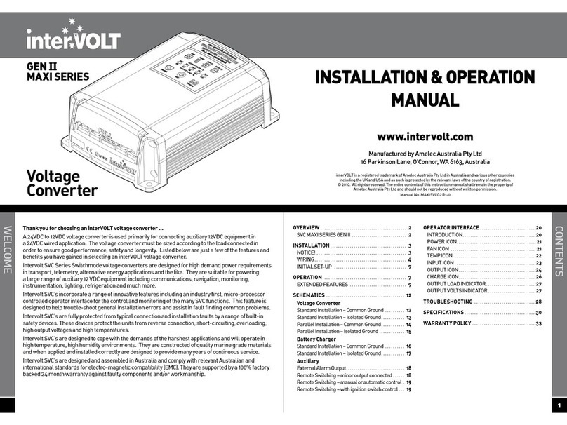
intervolt SVC Series Operating instructions

www.intervolt.com
SVC SERIES – SWITCHMODE VOLTAGE CONVERTER – INSTALLATION AND OPERATION GUIDE
Switchmode Voltage Converter
SVC Series
GENERAL
Intervolt SVC Series Switchmode Voltage Converters are
designed for high demand power requirements in both vessel
and vehicle applications. They are suitable for powering a large
range of auxiliary 12 VDC equipment including communications,
navigation, monitoring, instrumentation, lighting, refrigeration
and much more.
Intervolt SVC’s incorporate a range of innovative features
including an industry first micro-processor controlled, multi-
function diagnostic indicator. This feature is designed to help
trouble-shoot general installation errors and assist in fault
finding common problems.
Intervolt SVC’s are fully protected from typical connection
and installation faults by a range of built-in safety devices.
These devices protect the units from reverse connection,
short-circuiting, overloading, high output voltages and high
temperatures. The case of the unit is ungrounded therefore
ensuring electrical isolation.
Intervolt SVC’s are designed to cope with the harsh demands of
the marine environment. They are constructed of quality marine
grade materials and when applied and installed correctly are
designed to provide many years of continuous service.
Intervolt SVC’s are manufactured in Australia and comply with
both Australian and European Standards for Electro-Magnetic
compatibility. They are supported by a 100% factory backed 24
month warranty against faulty components and/or workmanship.
INSTALLATION
The SVC must be properly mounted in order to comply with
environmental considerations and the manufacturer’s warranty
terms and conditions. As the SVC is ungrounded it can be
mounted directly to any metal surface and maintain electrical
isolation.
1. Select a suitable location where the SVC can be mounted
on a vertical surface (i.e. bulkhead, firewall, etc.) with the
connection end facing downward .
2. Ensure SVC is located in a well ventilated position, free from
excessive moisture, dust, vibration and heat.
3. Fix the SVC with appropriate fasteners ensuring all anchor
holes are utilised.
4. Disconnect the 24VDC supply at the source before attempting
any connection to the SVC or auxiliary equipment.
5. Install an appropriately rated circuit breaker or fuse (see
chart) as the input protection for the 24VDC supply cable to
the SVC.
6. Connect all circuits to the SVC ensuring that adequate
cable sizes are used for model installed (consult your cable
supplier for correct current ratings).
7. Reconnect the 24VDC supply at the source. The LED
Diagnostic Indicator on the SVC should now be flashing
green intermittently. If there is no output supply refer to fault
finding section at rear of booklet.
Installation and
Operation Guide

Switchmode Voltage Converter
SVC Series
www.intervolt.com
TYPICAL UNGROUNDED INSTALLATION
WIRING DIAGRAM
TYPICAL GROUNDED INSTALLATION
FUSE
14
SVC
UNIT
FRONT
VIEW
FUSE
24 VDC
SUPPLY
12 VDC
LOAD
SVC
UNIT
FRONT
VIEW
24 VDC
SUPPLY
12 VDC
LOAD
1
234
Input Fuse or Circuit Breaker Selection
Model Rating
SVC241215
SVC241220
SVC241240
15 Amp
20 Amp
30 Amp
SVC241230 25 Amp
1
2
3
4
24 VDC Positive Input
0 VDC Internally Linked
as Common Negative
12 VDC Positive Output
3
See installation instructions on previous page
for additional information regarding connection
OPERATION
The SVC is designed to provide a constant supply at the rated
current for 12VDC equipment. The SVC is protected from a variety
of connection and application errors by a range of built in devices.
In most instances these errors are revealed by the diagnostic
indicator and can be corrected without having damaged the unit.
The SVC is protected in the following situations:
• Low Input Voltage If the input voltage falls below 17VDC the
SVC will be disabled. When the input voltage rises above this
setting the output supply will be restored.*
• High Temperature In the event the SVC exceeds the preset
temperature limit, the unit will be disabled. When the
temperature decreases the output supply will be restored.*
• Output Short Circuit If the output supply is short circuited
the SVC will be disabled. When the short is removed the
output supply will be restored.*
• Output Overload If the maximum current rating is
continuously exceeded the unit will be disabled. When the
load is reduced the output supply will be restored.
• Input Reverse Connection If the input terminals are reverse
connected the SVC will become inoperable. The input circuit
is diode controlled and protected by an internal fuse which is
not user serviceable.
• Output Over Voltage A Zener crowbar circuit prevents the
output supply from high voltage. The circuit is protected by
an internal fuse which is not user serviceable.
• Transient Input Voltage A purpose designed circuit filters
out surges and spikes.
* Refer diagnostics and fault finding section on next page for
trouble-shooting these problems.
WARRANTY
Intervolt products are warranted for a period of 24 months
against faulty materials and/or workmanship from date of last
sale or a maximum of 36 months from the date of manufacture
subject to the following terms and conditions.
• The goods must be installed and operated in accordance with
the manufacturers recommendations and instructions set
out within this booklet.
• In the event of a claim the goods are returned to the original
point of purchase with a copy of the merchant invoice or the
relevant merchant invoice number.
• In the event of a claim any associated expenses including
diagnosis, removal, and/or installation of the goods is the
responsibility of the client including any freight costs.
• The warranty shall be void where the goods have been used
for a purpose for which they are not intended, or altered in
any way that is detrimental, or opened or tampered with by
an unauthorised party, or damaged by mechanical abuse, or
contaminated by water or other substances, or damaged by
incorrect application.
• Save and except for the express warranty set out above and
to the maximum extent permitted by law, all conditions and
warranties which may at any time be implied by the common
law, Trade Practices Act, Fair Trading Act or any other State
or Federal Act are excluded. To the extent that these cannot
be excluded and where the law permits, the manufacturer in
respect of any such condition or warranty shall be limited at
their option to the repair or the replacement of the goods or
the supply of equivalent goods or refunding the cost of the
goods.
interVOLT is a registered trademark of Amelec Australia Pty Ltd. Amelec Australia Pty Ltd is
registered by the Australian Communications authority and authorised to use the ‘C’ Tick mark
accordingly. Our user number is N1816.
DIAGNOSTICS AND FAULT FINDING
Indication Status Cause Remedy
Pulsing Green System Normal N/A N/A
Pulsing Amber Over Temperature Lack of Ventilation Check and ensure ventilation to unit is adequate
Continuously exceeding Maximum Load rating Check loads to ensure they do not exceed rating of SVC
Pulsing Red Short Circuit or Overload Short Circuit on Output Load Remove load and check for short circuit
Continuously exceeding Maximum Load rating Check loads to ensure they do not exceed rating of SVC
Pulsing alternately Low Input Voltage Input Voltage has Check voltage of battery supply
Green/Red dropped below 17VDC
No indication Out of service Internal fault Return to authorised service centre
Table of contents
Other intervolt Media Converter manuals
Popular Media Converter manuals by other brands
AutomationDirect
AutomationDirect IronHorse GSDA-DP-S user manual
Silvercrest
Silvercrest SVG 2.0 A3 Operating instructions and safety instructions
Black Box
Black Box AC095A user manual
HIK VISION
HIK VISION DS-6700HUHI-K Series user manual
foc.us
foc.us Quadscan Elite user manual
Clear One
Clear One StreamNet AVoIP VIEW Pro Installation and user manual
