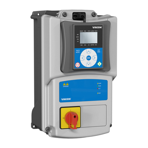
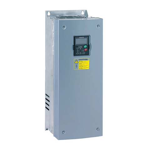
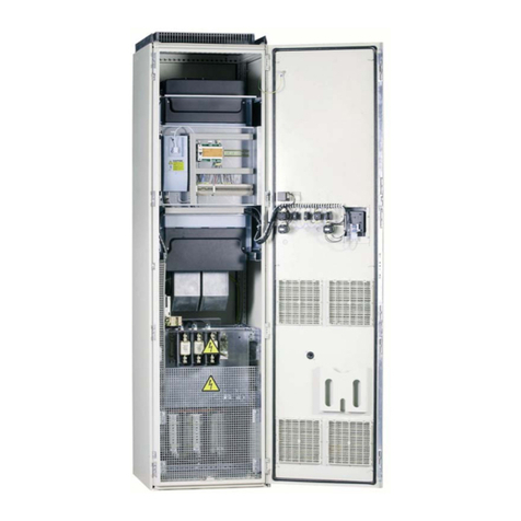
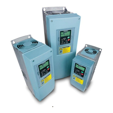
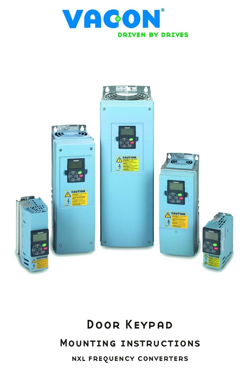
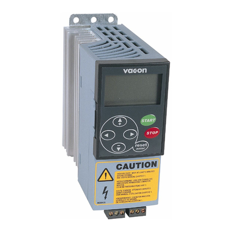
Vacon NX User manual

VACON NX SERVICE MANUAL
Overview

Table of contents
email: service vacon.com Tel: +358 (0)201 212 575 Fax: +358 (0)204 335 091
3
1. SERVICE MANUAL VERSION HISTORY...................................................6
2. AFTER MARKET SERVICE INFORMATION................................................8
2.1. Foreword ..................................................................................8
2.2. An overview of the manual information .........................................9
2.3. Appendix manual information .....................................................9
2.4. Important instructions for various service situations ..................... 10
2.4.1. Personal requirements ................................................ 10
2.4.2. Personal safety notice ................................................. 10
2.4.3. Material requirements ................................................. 11
2.4.4. Tool safety notice ....................................................... 11
2.5. Service policy .......................................................................... 11
2.6. Warranty terms ....................................................................... 12
2.7. Replacement units and spare parts ............................................. 12
2.8. Maintenance ............................................................................ 13
2.8.1. Recommended maintenance ........................................ 13
2.8.2. Recharging the capacitors in stored units ....................... 14
2.8.3. Recharging individual capacitors that have been stored ... 14
2.8.4. DC link capacitor tests and replacement ........................ 15
2.8.4.1.Test ............................................................. 15
2.8.4.2.Replacement .................................................. 15
3. SERVICE TOOLS ...................................................................................17
3.1. Information ............................................................................. 17
3.2. NC Load 1.0.17 ....................................................................... 17
3.3. NC Drive ................................................................................. 17
3.3.1. NC Drive 2.0.7 ........................................................... 17
3.3.2. NC Drive 2.0.8 ........................................................... 18
3.3.3. NC Drive 2.0.11 ......................................................... 18
3.4. NC SERVICE ............................................................................ 18
3.4.1. Software version 1.09 ................................................. 18
3.4.2. Software version 1.10 ................................................. 18
3.4.3. Software version 1.11 ................................................. 18
3.4.4. Software version 1.12 ................................................. 18
3.4.5. Software version 1.13 ................................................. 19
3.5. Device properties service .......................................................... 19
3.5.1. Version 2.0.2 ............................................................. 19
3.5.2. Version 2.0.3 ............................................................. 19
3.5.3. Version 2.0.4 ............................................................. 19
3.6. 3-PUT2 ................................................................................... 19
4. FAULTCODES AND SOFTWARE..............................................................20
4.1. General .................................................................................. 20
4.2. Fault codes ............................................................................. 20
4.2.1. NXL information ......................................................... 20
4.2.2. NXS/P information ...................................................... 23
4.3. Software revision information .................................................... 23

Table of contents
24h on-call service phone: +358 (0)40 83 71 150
4
4.3.1. NXL software information ............................................ 23
4.3.1.1.NXL00005V146 23
4.3.1.2.NXL00005V247 24
4.3.1.3.NXL00005V248 24
4.3.1.4.NXL00005V242 24
4.3.1.5.NXL00005V249 24
4.3.1.6.NXL00005V250 24
4.3.1.7.NXL00005V251 25
4.3.1.8.NXL00005V252 25
4.3.1.9.NXL00005V253 25
4.3.1.10.NXL00005V254 25
4.3.1.11.NXL00005V255 26
4.3.1.12.NXL00005V256 26
4.3.1.13.NXL00005V257 26
4.3.1.14.NXL00005V258 27
4.3.1.15.NXL00005V259 27
4.3.2. NXS software information ............................................ 28
4.3.2.1.NXS00001V160 28
4.3.2.2.NXS00001V161 28
4.3.2.3.NXS00001V162 28
4.3.2.4.NXS00001V163 28
4.3.2.5.NXS00001V164 28
4.3.2.6.NXS00001V165 28
4.3.2.7.NXS00001V166 29
4.3.2.8.NXS00001V167 30
4.3.2.9.NXS00001V168 31
4.3.2.10.NXS00001V169 31
4.3.2.11.NXS00001V170 32
4.3.2.12.NXS00001V171 32
4.3.2.13.NXS00001V172 32
4.3.2.14.NXS00001V173 33
4.3.3. NXP software information ............................................ 33
4.3.3.1.NXP00002V156 33
4.3.3.2.NXP00002V158 33
4.3.3.3.NXP00002V159 34
4.3.3.4.NXP00002V160 34
4.3.3.5.NXP00002V161 34
4.3.3.6.NXP00002V162 34
4.3.3.7.NXP00002V163 34
4.3.3.8.NXP00002V164 34
4.3.3.9.NXP00002V165 35
4.3.3.10.NXP00002V166 35
4.3.3.11.NXP00002V167 36
4.3.3.12.NXP00002V168 37
4.3.3.13.NXP00002V169 38
4.3.3.14.NXP00002V170 38
4.3.3.15.NXP00002V171 38
4.3.3.16.NXP00002V172 39
4.3.3.17.NXP00002V173 40
4.3.3.18.NXP00002V174 40

Table of contents
email: service vacon.com Tel: +358 (0)201 212 575 Fax: +358 (0)204 335 091
5
4.4. Information regarding fault tracing ............................................. 42
4.5. Fault codes ............................................................................. 43
4.5.1. Fault code flowcharts .................................................. 43
4.5.2. Defect code ............................................................... 86
5. SERVICE INSTRUCTIONS FOR OPTION OARDS.................................102
5.1. Basic tests ............................................................................ 102
5.1.1. Control board interface diagram ................................. 102
5.1.2. Test equipment VB300 and 3-BOXTEST ....................... 103
5.1.2.1.3-VB300 ...................................................... 103
5.1.2.2.3-BOXTEST .................................................. 104
5.1.3. Testing the Eprom by panel ....................................... 104
5.1.4. Testing the Eprom by Device Properties program .......... 105
5.2. NX option boards ................................................................... 105
5.2.1. Basic I/O boards NX OPT-A_ ...................................... 106
5.2.2. I/O Expander boards NX OPT-B_ ................................ 108
5.2.3. Fieldbus boards NX OPT-C_ ........................................ 110
5.2.4. Adapter boards NX OPT-D_ ........................................ 111
6. START-UP AFTER REPAIR...................................................................112
6.1. An external DC power without the motor for FR4 to FR13 ............ 112
6.2. Testing with a DC suppply without the motor connection ............. 112
6.3. Load test with motor .............................................................. 113

Revision history
24h on-call service: phone +358 (0)40 83 71 150
6
1
7. SERVICE MANUAL VERSION HISTORY
TABLE 1.
NX drive version history.
Service
manual
version Updated/added material
SM00002A First version
SM00002B Layout updated. Changes to following chapters: After market
service information (2nd), Service tools (3rd) and faultcodes
and software (4th).
SM00002C General update
SM00002D Service manual ID code table update.
TABLE 2.
NX drive component version history.
Name
New part
code
Old part
code
Valid
from Changes to previous
NXS Control board VB00252O VB00252N Esti-
mated
26.9.05
Current limit to panel
increased to 90mA

Revision history
email: service@vacon.com Phone: +358 (0)201 212 575 Fax: +358 (0)204 335 091
7
1

After market service information
24h on-call service phone: +358 (0)40 83 71 150
8
2
8. AFTER MARKET SERVICE INFORMATION
8.1. Foreword
Providing a modern efficient service for Vacon AC Drive owners is considered a high pri-
ority for Vacon Plc, as well as actively continuing to develop and introduce new service
material.
In line with this forward-thinking strategy, Vacon has published the following Vacon
Service Manuals for the Service Centers.
TABLE 3.
ID codes for Vacon NX Service manuals.
Product range Manual ID code
NX Overview SM00002
NXL MF2 SM00003
NXL MF3 SM00004
NXL MF4 SM00005
NXL MF5 SM00006
NXL MF6 SM00007
NXS/P FR4 SM00008
NXS/P FR5 SM00009
NXS/P FR6/500V SM000010
NXS/P FR6/690V SM000011
NXS/P FR7 SM000012
NXS/P FR8 SM000013
NXS/P FR9 SM000014
NXP FR10 SM000015
NXP FR11 SM000016
NXP FR12 SM000017
NXP FR13 SM000018
NXP FR14 SM000019
NX NFE9 G1 and G2 SM000032
NX FI9 SM00028
NX FI10 SM00029
NX FI12 SM00030
NX FI13 SM00031
NX FI MPA SM00039
NXP CH31 Not available! SM00020
NXP CH32 Not available! SM00040
NXP CH41 Not available! SM00021
NXP CH51 Not available! SM00022
NXP CH61 SM00023

After market service information
email: service vacon.com Tel: +358 (0)201 212 575 Fax: +358 (0)204 335 091
9
2
Other service information released by Vacon Plc, includes Service Bulletins (SBU´s,
BUF’s), which contain more detailed information about product updates.
Vacon Plc. periodically publishs updated service manuals, following the initial release of
each manual. The document version can be identified by the number and date printed
on the back cover of the document. The letter at the end of the SM-number identifies
the version, e.g. SM00002A. The material can be accessed by logging on to Vacon ser-
vice web pages, using the user name and password provided on request by the Vacon
After Market Service department.
8.2. An overview of the manual information
This manual contains the following chapters.
NOTE: S
OME
CHAPTERS
WILL
E
UPDATED
LATER
. A
DDITIONAL
INFORMATION
FOR
CERTAIN
STEPS
MIGHT
ALSO
EXIST
IN
APPENDIX
MANUALS
.
8.3. Appendix manual information
Separate appendix manuals contain the following chapters.
NXP CH62 SM00033
NXP CH63 SM00034
NXP CH64 SM00035
NXP CH72 SM00036
NXP CH74 SM00037
NX Maintenance JIG for FR11 SM00041
Vacon CX/CXL M4 - M10 SM00050
Vacon CX M11 - M13 SM00051
Vacon CXS SM00052
TABLE 4.
Chapter information in the overview manual.
Chapter Information
Revision history Short description about updates in manual.
After market service
information
Overall information about safety, service policy and
maintenance procedures for all NX-products.
Service tools Hints on how to use different PC-tools in service cases,
and the mechanical tools that are required.
Fault codes and software Procedures for fault codes and software information.
Option boards Basic instructions how to check different option boards.
Procedures after repair Steps that need to be taken after the physical repair
has been completed.
TABLE 3.
ID codes for Vacon NX Service manuals.
Product range Manual ID code

After market service information
24h on-call service phone: +358 (0)40 83 71 150
10
2
Note: Information about older drives may not be present in some appendix manuals.
8.4. Important instructions for various service situations
Review each procedure and section in advance. This chapter and its subchapters con-
tains important information, which must be applied in service situations.
•Local and national laws and regulations, concerning the service work to be per-
formed, must be followed.
•Vacon Plc. cannot be held responsible for personal injuries or material damage,
which may occur when local or national laws concerning service work have not been
followed.
•All plastic covers must be reinstalled on AC Drives before switching on the power
supply.
8.4.1. Personal requirements
Personnel performing service work must have qualifications that are in accordance with
the local and national laws.
WARNING! O
NLY
QUAKIFIED
SERVICE
TRAINED
PERSONNEL
ARE
ALLOWED
TO
USE
THIS
MATERIAL
AND
PERFORM
ANY
OF
THE
SERVICE
ACTIONS
MENTIONED
. T
HE
PERSONNEL
PRE
-
FORMING
LOCAL
SERVICE
WORK
ON
THE
DRIVES
MUST
HAVE
QUALIFICATIONS
THAT
ARE
IN
ACCORDANCE
WITH
THEIR
NATIONAL
LAW
.
8.4.2. Personal safety notice
Mechanical surfaces, which display a warning 'hot surface' sticker, must not be
touched. Make sure the working environment is safe, and there is nothing that will
cause any risk of personal injury.
WARNING! A
DRIVE
THAT
IS
TO
E
REPAIRED
MUST
NOT
E
POWERED
UP
DURING
SERVICE
WORK
,
UNLESS
IT
IS
SPECIALLY
MENTIONED
TO
DO
SO
IN
THE
SERVICE
INSTRUCTIONS
.
TABLE 5.
Chapter information in the appendix manuals.
Chapter Information
Updates in manual Short description about added or updated material.
Main circuit diagrams Contains different versions of the main circuit diagram.
Exploded view 3D-model(s) showing the spare part numbers
Measurement instruc-
tions
Instruction on how and where to measure different parts
and circuits.
Replacement instruc-
tions
Instruction on how to remove and replace different parts
or subassemblies.
Specifications Other instructions such as how to modify mass custom-
ized boards and torque lists.

After market service information
email: service vacon.com Tel: +358 (0)201 212 575 Fax: +358 (0)204 335 091
11
2
It is essential to understand that it is extremely dangerous for anyone to come in con-
tact with the following voltages, as it can result in death or severe personal injury. Do
not touch any electrical part, DC-bus bars included, when the unit is powered up.
•DC-bus voltage: After switching off the power supply, wait until the DC-bus voltage
has discharged. It must be first tested and shown to be 0V DC before any service
action is permitted. Beware: The voltage carried by the DC-bus is life threatening.
•Relay outputs on I/O boards: Even if the AC Drive unit itself is not powered up, the I/
O board relays may still carry dangerously high voltages from external devices. The
relay voltage must be checked and the necessary precautions taken to isolate them
properly before any service action is allowed. Beware: This voltages carried by relays
are life threatening.
•All power terminals carry voltages, including the output terminals, when the unit is
connected to its power supply and the DC-bus capacitors are charged.
•Internal components and circuit boards are at mains potential, when the AC Drive is
connected to its power supply and the DC-bus capacitors are charged.
8.4.3. Material requirements
•To maintain a safe construction and a safe operation of the complete AC Drive, the
internal torque specifications must be followed.
•The torque specifications for mounting the AC Drive and the torque specifications for
the
cable connections must be followed.
•Only use spare parts that are supplied by Vacon Plc.
•Every service location must carry all specialized Vacon AC Drive tools, the correct
measuring equipment, all of the necessary adapters and load motors for testing pur-
poses, along with the correct power supply for each AC Drive that is serviced, as
well as all of the spare parts that are required.
•Many procedures require a torque wrench to ensure the correct tightening torque in
accordance with the specifications.
8.4.4. Tool safety notice
•Electrical and mechanical tools used to perform service work, and replacement wir-
ing, must be in accordance with the requirements for the tools used and the recom-
mended work procedures..
•If tools are used that do not comply with the regulations governing servicing and
maintenance practice, damage will inevitably be caused to AC Drive units and the
environment.
8.5. Service policy
The service is to be performed at the nearest Service Center or at the customer loca-
tion by trained service personnel, or returned to the manufacturer's premises to be
serviced. All defective parts must be replaced with spare parts. It is not permitted to
allow any repairs to be carry out on boards.
Defective products up to FR8: The customer should get an equivalent product as a
replacement unit, while the service work is being performed at a Service Center. The
replacement unit is free of charge, if the product is under warranty, according to Vacon
warranty terms.

After market service information
24h on-call service phone: +358 (0)40 83 71 150
12
2
Defective products above FR8: They should be repaired by nearest Service Center at
the customer location, unless the manufacturer states otherwise.
VSRT-number: Any shipment of defective products and warranty claims sent to Vacon
Plc must both be identified with an issued VSRT-number (number of the Vacon Service
Report). The Local Service Center must send a VSRT-number request with the neces-
sary information via a PC-program (Vacon VSRT). Vacon Plc will respond to the request
by giving instructions on how to proceed. All shipments, in a service case to and from
Vacon Plc, must use an issued VSRT-number. The issued VSRT-number must be used
on all documents concerning the warranty claim. The shipment to Vacon Plc and all
shipment documents must be labeled with the issued VSRT-number. A missing RAN-
number in a shipment or shipment document, might result in the rejection of the ship-
ment and the warranty claim. More information from Vacon Service report Tool is avail-
able in vacon Extranet (http://www.extra.vacon.com/): VSRT Installation.pdf, VSTR
Userguide.pdf, SBU00022_0724. Vacon Service Report Tool is available at http://
www.extra.vacon.com/ . . . Service . . . Warranty .
All Service Centers around the world are a part of the Vacon global service network and
the local Service Center must provide adequate measures to ensure customer satisfac-
tion.
Only spare parts, which are specified and approved by Vacon Plc are to be used to
replace defect parts. Boards are to be repaired only at Vacon Plc. Service actions
defined in a released SBU (Service Bulletin) authorizes the repair or modification of the
board in question.
The warranty will be revoked from the unit, if repair actions have been carried out
without the proper authorization from Vacon Plc.
8.6. Warranty terms
Warranty terms are available at http://www.extra.vacon.com/ . . . Service . . . War-
ranty.
8.7. Replacement units and spare parts
Spare parts for servicing are listed at http://www.extra.vacon.com/ . . . Service . . .
Spare parts.
Each Vacon Service Center or Partner will store replacement units needed to enable a
fast response to every type of Vacon AC Drive service. The stock of the replacement
units should contain at least one unit of the biggest power size of every mechanical size
up to FR8. Vacon Plc will compensate for the stock of spare units in the case of a unit
that is under the manufacturer's warranty, which has been delivered to replace the
defective unit.
The Service Center will store spare parts based on units sold and needed for service in
their market / service area. If needed, Vacon Plc helps to select the required spares.
The spare parts must be stored properly to prevent material loss due to mishandling.

After market service information
email: service vacon.com Tel: +358 (0)201 212 575 Fax: +358 (0)204 335 091
13
2
Always protect components and boards from ESD, in all phases of the process, by fol-
lowing the general ESD instructions.
8.8. Maintenance
8.8.1. Recommended maintenance
Generally all technical equipment, including Vacon AC Drives, need a minimum level of
case and failure preventive maintenance to continually function properly. To maintain a
trouble free operation of the drive, environmental conditions, as well as load, line
power, process control, etc. have to be within the specifications, determined by the
manufacturer.
If all conditions are as specified by the manufacturer, there is no other concerns, but to
provide a high enough cooling capacity for the power and control circuits. This require-
ment can be met by making sure that the cooling system works properly. The operation
of the cooling fans and the cleanness of the heat sink should be checked once in a
while.
Regular maintenance is recommended to ensure trouble free operation and long life of
the drive. The following things should, at least, be included in the regular maintenance
program.
It is also recommended, as a good service practise for follow up maintenance, that the
counter values, dates and time are always recorded along with the service actions.
TABLE 6.
Maintenance interval
Interval Maintenance
6-12 months (used unit/cabinet) Change the door filters
12 months (if the unit is stored) Capacitor reforming, see sepa-
rate instructions
6 - 24 months (depending on the
environment)
Check the input and output ter-
minals and control I/O-terminals.
Clean the cooling tunnel
Check the operation of the cool-
ing fan, check for corrosion on
the terminals, bus-bars and other
surfaces
Check the door filters in the case
of cabin installation
5 - 7 years Change the cooling fans:
Main fan
Internal IP54 fan
Cabinet cooling fan/filter
5 - 10 years Change the DC bus capacitors

After market service information
24h on-call service phone: +358 (0)40 83 71 150
14
2
8.8.2. Recharging the capacitors in stored units
When complete AC Drive units are stored without any voltage being applied to them,
the recharging of the capacitors should be done at least every 12 months, by connect-
ing the power supply to the unit and then keeping the unit powered up for a minimum
of one hour.
If the storing time is much longer than one year, the recharging of the capacitors has to
be done in a way that possible high leakage current through the capacitors is limited.
The best alternative is to use a DC-power supply with an adjustable current limit. The
current limit has to be set, for example, to 300…500mA and the DC-power supply has
to be connected to the B+/B- terminals (DC+ to B+, DC- to B-) of the DC-link or
straight to the capacitor terminals.
NX product, which have no B+ / B- terminals, can be powered up as follows:
•Frame size FR8-FR9: the DC supply is connected between the two input phases L1,
L2.
•The DC voltage has to be adjusted up to the nominal DC voltage level of the unit
(1.35*Un AC) and has to be supplied for at least one hour.
•If a DC voltage is not available and the unit has been stored much longer than one
year de-energized, consult the manufacturer before connecting the power.
8.8.3. Recharging individual capacitors that have been stored
When using spare part capacitors from stock and it is known that they have been
stored there for over one year uncharged, it is easiest to recharge the capacitors before
they are installed in a unit.
The DC power supply current limit is set to 50…100 mA and the voltage is set to the
rated value of capacitors. The recharging process can be then followed by monitoring
the current meter of the DC-power supply. It is recommended to keep voltage supplied
for at least one hour even though the leakage current has already stabilized earlier.
Due to high leakage resistance, a dangerously high voltages can remain in capacitors
for a long time. So, remember to discharge the capacitors, by using the correct dis-
charging resistor, after the recharging is finished.
FIGURE 1. How to connect the DC power supply
+-
+
-
VI
R

After market service information
email: service vacon.com Tel: +358 (0)201 212 575 Fax: +358 (0)204 335 091
15
2
8.8.4. DC link capacitor tests and replacement
8. 8. 4. 1. Test
The condition of each capacitor must be verified when:
•A short circuit has occurred in the main circuit of the IGBT
•A capacitor has short circuited
•Any short circuit between different voltage potentials has occurred in the DC-link
8. 8. 4. 2. Replacement
Replacement of the capacitors, when there is a short circuit in the capacitor.
•All capacitors which are inter connectioned in the same bank between DC+ and DC-.
See Figure 2.
All capacitors should be replaced when the drive has been used for the period of time
specified in chapter “Recommended maintenance”, when considering the load, environ-
ment temperature and humidity.
FIGURE 2. Capacitor replacement.
%URNHQFDSDFLWRU&DSDFLWRUVZLWKGLUHFWSDUDOOHOLQWHUFRQQHFWLRQV

After market service information
email: service vacon.com Tel: +358 (0)201 212 575 Fax: +358 (0)204 335 091
16
2

Service tools
email: service vacon.com Tel: +358 (0)201 212 575 Fax: +358 (0)204 335 091
17
3
9. SERVICE TOOLS
9.1. Information
The latest versions of the NCLoad and NCDrive are available at http://www.vacon.com
(-> Support & downloads -> Vacon NX software and tools). The latest software ver-
sions of the programs NCService and Device Properties Service are available at http:/
/www.vacon.extra.com. It also includes useful hints, “Nice to know”, for the different
programs.
The Device Properties Service is a password protected program, which only the world-
wide Vacon service centres are permitted to use.
In addition to the general information about the list of tools needed to service AC
drives, it also contains a list of tools needed for each service case.
9.2. NC Load 1.0.17
For information on how to use the program, please refer to “Contents”, in the “Help”-
menu. The “Nice to know” information is as follows:
•When a problem with an eeprom on a control, power or option board is suspected,
“F40” or “?” is displayed.
->Obtain “Info”. “Info” is located under the “Drive” menu. A new window opens, and
the content can be copied to the clipboard with the “Copy To Clipboard” push button.
9.3. NC Drive
See complete list of release information for NCDrive on the web page, http://
www.vacon.com (-> Vacon NX software and tools -> Vacon NC Drive).
For information on how to use the program, please refer to “Contents”, in the “Help”
menu.
The “Nice to know” information is as follows.
9.3.1. NC Drive 2.0.7
•When a problem with an eeprom on a control, power or option board is suspected,
“F40” or “?” is displayed:
-> Obtain “Info”. “Info” is located under the “Drive” menu. A new window opens, and
the content can be copied to the clipboard with the “Copy To Clipboard” push button.
•For the most complete troubleshooting information parameters, eeprom settings or
faultcodes, when a customer contacts you:

Service tools
24h on-call service phone: +358 (0)40 83 71 150
18
3
-> Obtain “Print Service Info To File”. “Print Service Info To File” is located under “File”
menu. A txt-file is generated containing the parameter settings, eeprom data and fault
codes, if listed.
9.3.2. NC Drive 2.0.8
•There are total four sets of dataloggers data available. All the individual sets can be
retrieved from the drive using NC Drive. The advanced datalogger option can be
enabled in Tools/Options/Datalogger menu.
•Print Service Info' and 'Print Service Info To File...' menus has been moved to a
menu called 'Service Menu...' which opens a window that user can print or save.
•Monitor window can be opened without any application VCN file. All firmware signals
can still be monitored for debugging during the service.
•BACNet fieldbus (OPTCJ) board is now supported.
9.3.3. NC Drive 2.0.11
The latest version is available on Vacon extranet.
9.4. NC SERVICE
NC Service supports NXS and NXP testing, but not NXL testing.
9.4.1. Software version 1.09
Does not support the testing of NXL or NXP2-control board.
9.4.2. Software version 1.10
9.4.3. Software version 1.11
•Test file “TESTER_NXP661.S” supports the control boards VB00561H and
VB00661A.
•Logic active levels changed: ~4V on VB00251 (NXP) and ~5V on VB00561 and
VB00661 (NXP2)
Signals:
•GLOBAL_STOP/B0V
•PWM_2B0V
are removed from the slot B on the control boards VB00561H and VB00661.
9.4.4. Software version 1.12
Fully installation needed to update NC Service version 1.11 to the version 1.12. Pro-
gram window will open to the right corner of the screen.

Service tools
email: service vacon.com Tel: +358 (0)201 212 575 Fax: +358 (0)204 335 091
19
3
9.4.5. Software version 1.13
Includes Windows Vista support.
9.5. Device properties service
A Program is required for programming the control unit, power unit and star adapter
unit in service cases. A Previously installed NCLoad or NCDrive is needed before the
program is operational. The Password protected file intended is only for authorized
personnel. Ask for the password from your contact in the After Market Service.
9.5.1. Version 2.0.2
The Brake chopper been added as default to the programming and there have been
changes to the drive ratings in pull-down menus.
9.5.2. Version 2.0.3
Support for newer system software versions which require ExtraData[3] = 3. This is
the default in easy mode. User-manual V1.3 included.
9.5.3. Version 2.0.4
•Updated user’s manual and program.
•Possible to rescale the window.
•Previously installed NCLoad or NCDrive required.
•Password protected file intended only for authorized service centres.
9.6. 3-PUT2
The tool traces the faults and verifies the functionality after the service. More informa-
tion on Vacon Extranet at http://www.extra.vacon.com. There is 3-PUT2 user’s man-
ual available, too.

Fault codes and software
24h on-call service phone: +358 (0)40 83 71 150
20
4
10. FAULTCODES AND SOFTWARE
10.1. General
Testing and troubleshooting are one of the first steps in service / repair procedures to
locate and identify defective part from the device. Troubleshooting gives good figure
for further measures, what have to be done to recover unit back in decent condition
and in an operation.
Careful troubleshooting and testing in prior to repair saves total time and surely pre-
vents additional consequential damages if done correctly.
Troubleshooting in general level for the complete drive is described in this section.
This section refers to checking instructions for respective frame size in its "NX Appen-
dix Manual".
10.2. Fault codes
All fault codes are described in flow charts below with an explanations and with mea-
sures to be done in different cases for solving the problem.
10.2.1. NXL information
NXL fault history can contain up to 5 faults and the oldest fault will dissapear. There is
none of save operation to the monitoring values in the fault history.
There is always a reason for the tripping of the drive and it should be solved before to
proceed in an operation and to avoid damages in equipment.
Some fault codes contain individual sub fault codes. A fault code has got a subfault
code if there is a dot after the fault number. Subcodes in the NXL will be found only
from the panel.
F1. 8 = there is a subfault code, fault 1 is system fault. Subcode is seen after a few
second push button to the right.

Fault codes and software
email: service vacon.com Tel: +358 (0)201 212 575 Fax: +358 (0)204 335 091
21
4
F2. 2 = there is not any subfault code. The second fault code is 2, overvoltage.
TABLE 7.
Fault codes in NXL unit.
Fault code Subcode Explanation
F1 S1 Normal Overcurrent trip
F1 S2 In MF2, MF3, MF4 the trip causes from current
measurement of the DC-link.
F1 S3 Software trip. Activated after 0.6 sec if the cur-
rent control had adjusted frequency to zero but
the current is higher than IL (load current). Too
high zero point voltage.
F2 Overvoltage
F3 Earth fault based on software. Sum of phase cur-
rents is not zero.
F5 Charging switch. This fault does not exist in the
NXL although the fault appears in the manual.
F8 S1 Driver fault. MF2, MF3, MF4 Driver circuit fault
signal. Appears also with F1 and F2.
F8 S2 Internal fault. Modulator assert.
F8 S3 Failed data reading on the EEPROM. No connec-
tion to the EEPROM.
F8 S4 Failed data in power section of the EEPROM.
F8 S5 Unknown power section. Size grade index 0.
F8 S6 VB-number of power board is not acceptable. Unit
can not identify the frame of power section.
F9 Undervoltage. Based on software.
F11 Output phase supervision. Based on software.
F13 Frequency converter undertemperature.
F14 Frequency converter overtemperature.
F15 Motor stalled. Based on software.
F16 Motor overtemperature. Based on software.
F17 Motor underload. Based on software.
F22 S1 Checksum error. Parameter (HMI retry, HMI time-
out, default page, default page time out, parame-
ter edit lock, breakresistor, fancontrol) has
EEPROM CRC error and returned to default value.
Other manuals for NX
11
Table of contents
Other Vacon Media Converter manuals

Vacon
Vacon asfiff12 User manual

Vacon
Vacon alfiff28 User manual

Vacon
Vacon NX series User manual

Vacon
Vacon X5OPT01 User manual

Vacon
Vacon CX User manual

Vacon
Vacon CX Series User manual

Vacon
Vacon NXL series User manual

Vacon
Vacon CX User manual

Vacon
Vacon NX Liquid Cooled User manual

Vacon
Vacon CXL User manual
Popular Media Converter manuals by other brands

YOKOGAWA
YOKOGAWA JUXTA VJB1 user manual

CONNECTRIC
CONNECTRIC moTrona FU 252 operating instructions

Plextor
Plextor Convertx PX-M402U Installation and user manual

Extron electronics
Extron electronics HAE 100 user guide

M-system
M-system M8CTC instruction manual

Renishaw
Renishaw QUANTiC RTLC40 installation guide