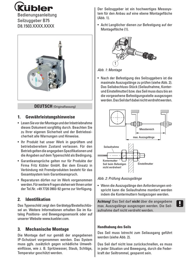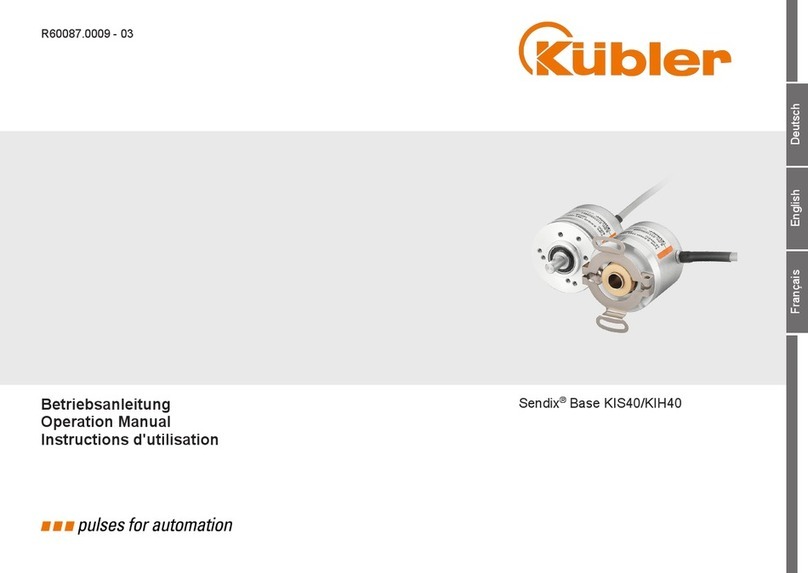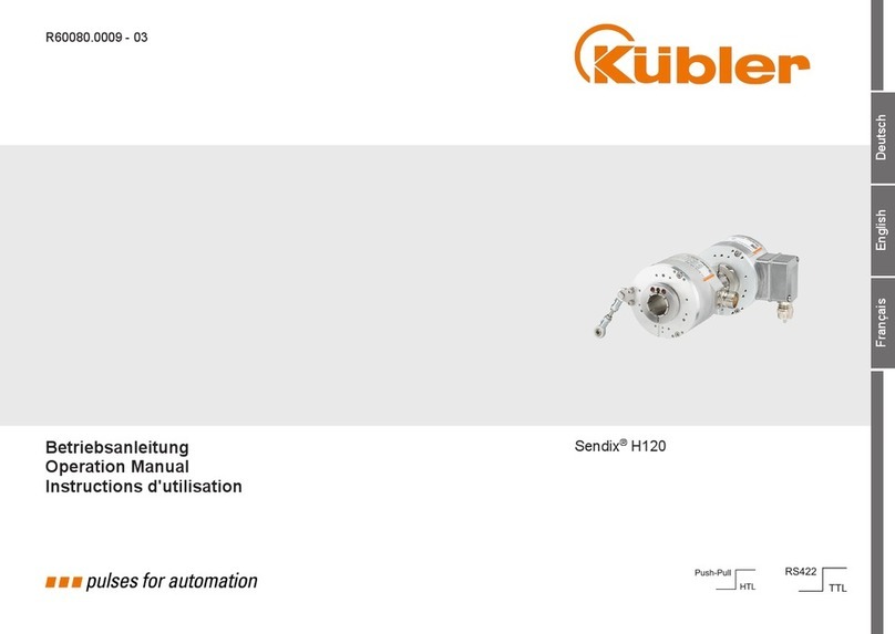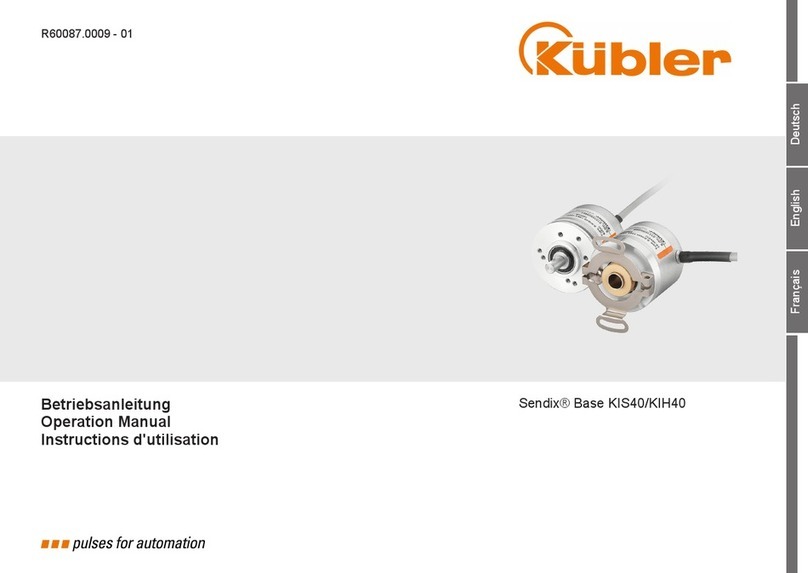
Installationsanleitung - Sendix 5020 (Bestellschlüssel 8.5020.00X4.YYYY.S223, 8.5020.00X4.YYYY.S224)
Installation manual - Sendix 5020 (Order code 8.5020.00X4.YYYY.S223, 8.5020.00X4.YYYY.S224)
R62813.0009 - Index 1
Achtung: Die Montage und Inbetriebnahme
ist von einer Fachkraft für Elektrik und
Feinmechanik unter Beachtung der örtlichen Sicherheitsvorschriften
vorzunehmen. Die Steckverbindung darf nur spannungsfrei verbunden
oder gelöst werden. Kabelschirm mit Gehäuse, Statorkupplung und Welle
verbunden.
Elektrische Installation des Drehgebers
Bitte trennen Sie vor Stecken/Lösen der Signalleitung immer die Versor-
gungsspannung.
Zum Anschluss des Drehgebers muss die entsprechende Betriebsanlei-
tung des externen Antriebssystems/Geberauswertung beachtet werden.
EMV Hinweise
• Verwenden Sie nur geschirmte und paarig verseilte Leitungen für
das Drehgeberkabel.
• Legen Sie den Schirm großächig und beidseitig auf Masse. Achten Sie
auf eine einwandfreie Befestigung der Leitungsschirme.
• Achten Sie bei der Verdrahtung Ihrer Anlage auf eine ordnungsgemäße
Leitungsführung. Trennen Sie die Verkabelung in Leitungsgruppen wie
Motor-/Stromversorgungsleitungen und Signal-/Datenleitungen.
Führen Sie Signal- und Datenleitungen möglichst eng an Masseächen
(Tragholmen, Metallschienen, Schrankblechen) und nicht parallel zu
Motor und Stromversorgungsleitung.
• Verbinden Sie alle Betriebsmittel impedanzarm mit dem Erdungs-/
Schutzleitersystem.
Allgemeine Hinweise
1. Geltende Sicherheitsnormen:
• Vor Inbetriebnahme sind alle benötigten Kabeladern laut Datenblatt
anzuschließen! Isolieren Sie alle nicht benötigten Enden der Aus-
gangssignale sauber, um Kurzschlüsse zu vermeiden. Werden die
Eingangssignale (SET, DIR) nicht verwendet, sollte der Eingang
auf 0 V (Masse Drehgeber GND) gelegt werden, um Störungen zu
vermeiden.
• Bei der Konfektionierung des Gegensteckers ist eine, evtl. dem
Stecker beigelegte, Anleitung zu beachten.
An Leistungslängen empfehlen wir:
• Bei symmetrischer Übertragung gemäß Tabelle 1 (Leitungslänge mit
verdrillten Aderpaaren).
• Gegenstecken am Geber nur im spannungslosen Zustand ziehen oder
stecken.
• Die richtige Betriebsspannung und den maximal zulässigen Aus-
gangsstrom berücksichtigen (siehe Datenblatt).
• Bitte verwenden Sie eine Versorgungsspannungsquelle gemäß PELV.
• Ein- bzw. Ausschalten der Betriebsspannung für den Geber und das
Folgegerät muss gemeinsam erfolgen.
2. Um CE-Konformität zu erreichen, ist eine EMV-gerechte Installation
Voraussetzung:
• Als Steuerleitungen sind durchgehend geschirmte Kabel zu
verwenden. Bei symmetrischer Übertragung (z.B. RS422) muss ein
Kabel mit verdrillten Aderpaaren verwendet werden. Der Kabelschirm
wird idealerweise rundum (360°) über schirmbare Stecker oder Kabel-
durchführungen an den Geber und die Auswertung angelegt.
• Die Schutzerde (PE) ist bevorzugt beidseitig, am Geber und an der
Auswertung, impedanzarm aufzulegen.
• Bei Problemen durch Erdschleifen ist die Schutzerde (PE) auf der
Geberseite aufzutrennen. Der Geber sollte hierbei gegenüber dem
Antrieb elektrisch isoliert angebaut werden.
• Die Geberleitungen sind getrennt von Leitungen mit hohem Störpegel
zu verlegen.
• An der Spannungsversorgung des Gebers sollten keine Verbraucher
mit hohem Störpegel, wie z.B. Frequenzumrichter, Magnetventile,
Schütze etc. angeschlossen werden. Andernfalls ist für eine geeignete
Spannungslterung zu sorgen.
Electrical installation of the encoder
Please always disconnect the power supply before connecting or dis-
connecting the signal line.
Comply with the corresponding operating instructions of the external drive
system/controller when connecting the encoder.
EMC information
• Use only shielded twisted-paired conductors as encoder cables.
• Connect the shield at both ends to the ground on a large contact
area. Make sure that the cable shields are well fastened.
• When wiring your installation, take care to route the cables
properly. Separate the wiring in cable groups such as motor / power
supply cables and signal / data cables. Route the signal and data cables
as close as possible to grounded surfaces (supporting beams, metal rails,
cabinet sides) and not parallel to motor and power supply cables.
• Connect all equipment with low impedance to the ground/protective
conductor system.
General information
1. Safety standards in force:
• Before commissioning, all required cable wires are to be connected
in compliance with the data sheet! Insulate all unused ends of the
output signals properly in order to prevent any short-circuit.
If this inputs (SET, DIR) are not used, it should be connected to 0 V
(Encoder ground GND) in order to avoid interferences.
• When confectioning the mating connector, observe the instructions
possibly attached to this connector.
Recommended cable lengths:
• For symmetric transmission according to table 1 (cable length
with twisted pairs).
• Connect or disconnect the mating connector only when the
encoder is switched off.
• Respect the proper operating voltage and the maximum
allowable output current (see data sheet).
• Please use a PELV-compliant supply voltage source.
• The operating voltage of the encoder and of the controller
must be switched on and off simultaneously.
2. An EMC-compliant installation is the prerequisite for achieving
CE conformity:
• Use totally shielded cables as control cables. In case of symmetric
transmission (e. g. RS422), use a cable with twisted wire pairs. The
shield of the cable is ideally applied on the encoder and on the cont-
roller through the complete periphery (360°) of shieldable connectors
or cable feedthroughs.
• The protective earth (PE) is to be applied preferably on both
sides, on the encoder and on the controller, with low
impedance.
• In case of problems due to ground loops, disconnect the
protective earth (PE) from the encoder side. The encoder should then
be electrically insulated from the drive.
• The encoder lines must be routed separately from cables with
high interference levels.
• No electrical devices with high interference levels such as
e. g. frequency converters, solenoid valves, contactors, etc., should be
connected to the voltage supply of the encoder. Otherwise, a suitable
voltage ltering must be provided.
Note: Mounting and commissioning is to be
conducted by a specialist in electrical
equipment and precision mechanics under compliance with local safety re-
gulations. Do not engage or disengage any connections while under power.
Cable shield connected to housing, stator coupling and shaft.
Deutsch (Originalversion) English (German is the original version)
X = Schnittstelle, Y = Impulszahl / X = Interface, Y = Pulse per revolution


