intervre IVR-6126 Series User manual

www.inte rvre.com
IVR-6126
Handheld Gigabit Ethernet
TestSet User Guide
IVR-6126 handheld gigabit Ethernet
test set is one of interVRE’s handheld
test products. It is designed for Ethernet
network deployment and comprehensive
test. IVR-6126 fully meets Ethernet
standard, oering complete ethernet test
funconalies with lightweighted, exible
and rugged qualies. It can be applied
to indoor laboratory or outdoor eld
environment and provide carrier-class.
Ethernet test soluon for network expert.
Lightweighted, compact, rugged, flexibly used in outdoor field environment
Quick power on, high-resolution color touch screen
Friendly key design for flexible scrolling and selecting
More comprehensive test function, higher cost-effective
Offer complete gigabit Ethernet solution from installation and
commissioning to operation and maintenance

IVR-6126 Series User Guide
2
Revision History
The following tables shows the revision for this document.
The product and the user guide could be upgraded or modied without noce. Please visit the website of
InterVRE (www.intervre.com) or contact us for the further informaon.
Date Version Revision
18/04/2011 1.0 Inial Release
3/07/2015 2.0 Revised the whole document;
New interface;
12/08/2015 2.10 Add Constant transmit mode in Table 7.6: Frame Analysis
Conguraon: Trac Shaping;
Add Power saving mode in Table 8.3: System Seng: Power.

IVR-6126 Series User Guide
3
Contents
1. Introduction 8
2. Description 9
2.1.1 Front Panel Diagram 9
2.1.2 LED Indicators 9
2.1.3 Buons 10
2.2.1 Right Panel Diagram 11
2.2.2 Interfaces 11
2.3.1 Top Panel Diagram 11
2.3.2 Interfaces 11
3. Specifications 13
3.2.1 AC/DC Adapter 13
3.2.2 Rechargeable Lithium-Ion Baery 13
4. Safety Information 15
5. Installation of the Device 17
6. Ethernet/PTN User Interface 20
7. Start a Test Case 22
8. Toolbar 55
9. Maintenance 68
Content

IVR-6126 Series User Guide
4
10. Troubleshooting 69
11. Warranty 71
Content

IVR-6126 Series User Guide
5
Contents of Tables
Table 2.1 LED Indicator Denions 9
Table 2.2 Buons Descripon 10
Table 2.3 Interfaces Descripon 11
Table 2.4 Interfaces Descripon 11
Table 3.1 Environmental Ranges 13
Table 3.2 Input and Output Requirement 13
Table 3.3 Other Physical Specicaons 14
Table 5.1 Turn On or O Instrucon 17
Table 5.2 Applicaon Installing or Upgrading
Hardware Requirements 17
Table 5.3 10G XFR Opcal Module 19
Table 7.1 Port Set 24
Table 7.2 RFC2544 Data Stream Generaon 27
Table 7.3 RFC2544 Seng 33
Table 7.4 RFC2544 Results 36
Table 7.5 Ethernet Test Results 39
Table 7.6 Frame Analysis Conguraon 43
Table 7.7 Ethernet Test Results (Frame
Analysis) 45
Table 7.8 Bit Error Injecon 47
Table 7.9 Loopback Seng 48
Table 7.10 Y.1564 Conguraon 49
Table 7.11 Y.1564 Results 51
Table 7.12 Jier Conguraon 52
Table 7.13 Jier Results 53
Table 7.14 User-dened Packet 54
Table 8.1 Prole 55
Table 8.2 Tools 56
Table 8.3 System Seng 63
Table 8.4 Bi-direconal Test 65
Table 10.1 Common Problems and Soluons 69
Content

IVR-6126 Series User Guide
6
Figure 2.1 IVR-6126 Handheld Gigabit Ether-
net Test Set Front Panel View 9
Figure 2.2 IVR-6126 Handheld Gigabit Ether-
net Test Set Right Panel View 10
Figure 2.3 IVR-6126 Handheld Gigabit Ethernet
Test Set Top Panel View 11
Figure 2.4 IVR-6126 Handheld Gigabit Ethernet
Test Set Boom Panel View 12
Figure 5.1 Explore 16
Figure 6.1 Main Interface of 10G Ethernet/PTN
Applicaon 20
Figure 6.2 Status Bar 20
Figure 6.3 Funcon Selecon 21
Figure 6.4 Toolbar 21
Figure 7.1 Step1: Select Port Set 22
Figure 7.2 Step2: Set RFC2544 Data Stream 22
Figure 7.3 Step3: Set RFC2544 Parameters 23
Figure 7.4 Step4: Run RFC2544 Test 23
Figure 7.5 Step5: View the Test Results 23
Figure 7.6 Port Seng 24
Figure 7.7 Network Seng 25
Figure 7.8 Network Seng 26
Figure 7.9 Power and Frequency 26
Figure 7.10 IEEE 802.3/802.2 SNAP Frame Format 27
Figure 7.11 MPLS Label Format 27
Contents of Figures
Figure 7.12 Frame Conguraon 27
Figure 7.13 VLAN Conguraon Dialogue Box 29
Figure 7.14 MAC 29
Figure 7.15 Advanced TOS/DS 31
Figure 7.16 IP 31
Figure 7.17 UDP/TCP 31
Figure 7.18 Paern 32
Figure 7.19 Select Test Funcons 33
Figure 7.20 Global Seng 33
Figure 7.21 Throughput Seng 34
Figure 7.22 Back-to-Back Seng 35
Figure 7.23 Frame Loss Seng 35
Figure 7.24 Latency Seng 36
Figure 7.25 Frame Status 39
Figure 7.26 Frame Size 40
Figure 7.27 Frame Type 40
Figure 7.28 Alarm Bert 1 41
Figure 7.29 Alarm/Bert 2 41
Figure 7.30 Logger 41
Figure 7.31 Graph 42
Figure 7.32 Save 42
Figure 7.33 Overview 36
Figure 7.34 Throughout Result 37
Content

IVR-6126 Series User Guide
7
Figure 7.35 Back to Back 37
Figure 7.36 Frame Loss 38
Figure 7.37 Latency 38
Figure 7.38 Graph mode 38
Figure 7.39 Overview (Frame Analysis) 43
Figure 7.40 Trac Shaping 44
Figure 7.41 Stream Stasc 1 45
Figure 7.42 Steam Stascs 1 to 3 45
Figure 7.43 Stream Stasc 3 45
Figure 7.44 Service Disrupon 46
Figure 7.45 Bit Error Injecon 48
Figure 7.46 Loopback 49
Figure 7.47 Y.1564 50
Figure 7.48 Y.1564 Result (Service) 51
Figure 7.49 Y.1564 Result (Summary) 51
Figure 7.50 Jier 52
Figure 7.51 Jier 53
Figure 7.52 User-dened Packet 54
Figure 8.1 Result 55
Figure 8.2 Report 55
Figure 8.3 Test 56
Figure 8.4 Seng 57
Figure 8.5 Ping Setup 57
Figure 86 Trace Route 58
Figure 8.7 VC T Test 58
Figure 8.8 Flow Control 59
Figure 8.9 Service Scan 60
Figure 8.10 FTP 60
Figure 8.11 HTTP 61
Figure 8.12 Filter 61
Figure 8.13 Capture 62
Figure 8.14 Topology 62
Figure 8.15 District 63
Figure 8.16 District 63
Figure 8.17 IP Seng 64
Figure 8.18 Remote Desktop 64
Figure 8.19 About 64
Figure 8.20 Power 65
Figure 8.21 Bi-direconal Test Ourselves Device 66
Figure 8.22 Bi-direconal Test Partner Device 66
Figure 8.23 Remote Alarm 67
Content

IVR-6126 Series User Guide
8
1.1 Overview
IVR-6126 Handheld Gigabit Ethernet Test Set is one of Ethernet test product of INTERVRE.
The product fully meets Ethernet standards (ITU-T Y.1564, IETF RFC2544, IETF RFC3393, IEEE
802.3, IEEE802.1 etc.,), and supports Ethernet WAN and LAN network test with high reliability,
convenience, and exibility. Meanwhile, the module can provide a high ecient SLA test funcon
for service provider.
The PTN test module is specially designed for tesng PTN (Packet Transport Network) of mobile
backhaul transport network. It fully meets IEEE; ITU-T; and RFC standards, and supports a
comprehensive test of PTN to provide performance guarantee for PTN business. Also it can support
155M; 622M; and 2.5G SDH/PDH test. Customers can depend on their various test demands during
the establishment of PTN network to select or customise these oponal test funcons.
1.2 Main Features
IVR-6126 Handheld Gigabit Ethernet Test Set has the following features:
• Interface user-friendly, operaon simply, and durable;
• High resoluon LCD colour touchable screen;
• Support all Gigabit Ethernet tests;
• Rapid start technology;
• Baery life: more than 8 hours.
1. Introduction
Introduction
IVR-6126 Series User Guide
9
2.1 Front Panel
2.1.1 Front Panel Diagram
Figure 2.1 IVR-6126 Handheld Gigabit Ethernet Test Set Front Panel View
2.1.2 LED Indicators
LED locaons for all LEDs on IVR-6126 has been shown in Figure 2.1. Table 2.1 describes the
LEDs placed on IVR-6126 as indicators.
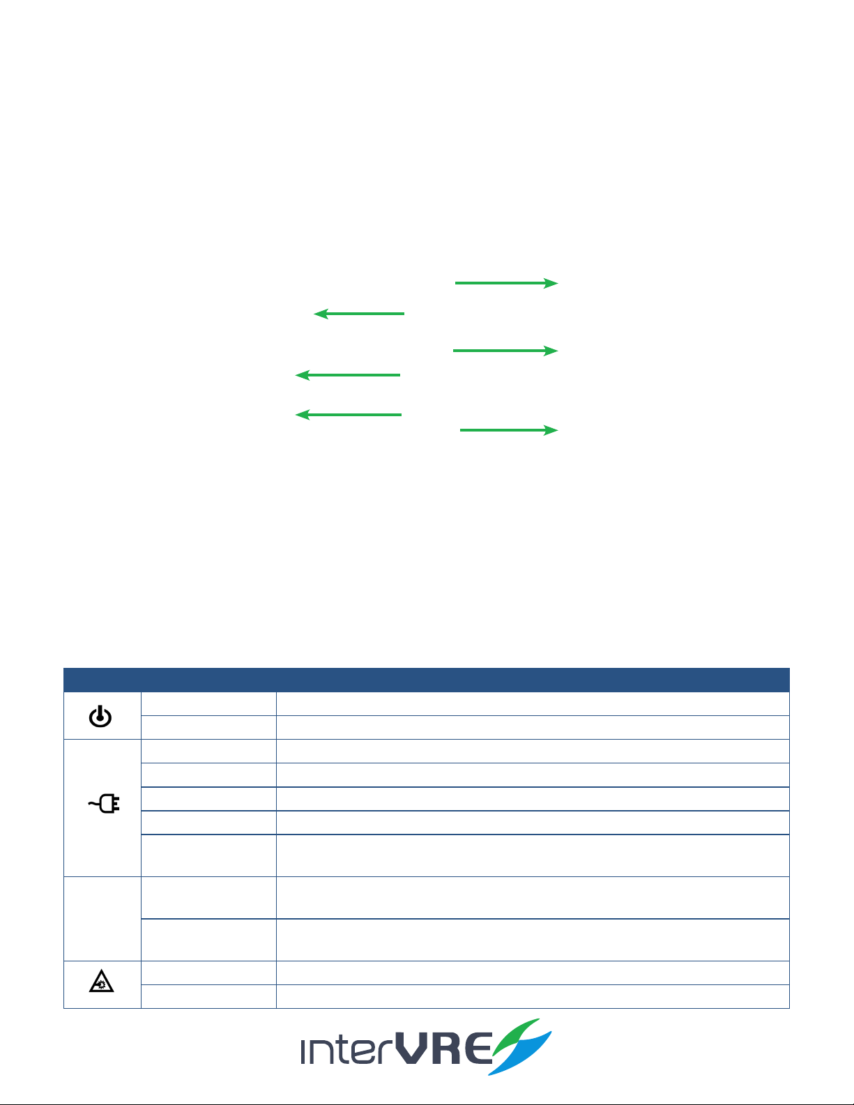
Table 2.1 LED Indicator Definitions
2. Description
LED
Green On
O O, and unplugged in
Green Plugged in and baery is fully charged
Green (ashing) Baery is on charge
Red (ashing) Unplugged in, and baery is weak
Red Baery error
O O
Unplugged in, and baery level is above the ‘crical threshold’
Green Result status: success ( Current result of the applicaon does not exceed the
predened threshold)
Red Result status: failure (Current result of the applicaon exceeds the predened
threshold)
Green (ashing) Laser status LED, at least one module is transming an opcal signal
O No module is transming signal
Description
LED Indicators
Funcon Key
On/O Buon
Number Key
Direcon Key
Colour Touch Screen

IVR-6126 Series User Guide
10
2.1.3 Buttons
Table 2.2 describes the funcons of IVR-6123 Handheld OTDR Test Set’s buons.
Table 2.2 Buttons Description
2.2 Right Panel
2.2.1 Right Panel Diagram
Figure 2.2 IVR-6126 Handheld Gigabit Ethernet Test Set Right Panel View
DC Connector
USB Port (Type A)
RJ 45 Port
USB Port (Type B)
Button Description
F1, F2, and F3 Funcon keys: Select the one sub menu from main menu displayed on the screen
Funcon keys: Switch the main menu
CANCEL X Cancel/Exit
OK √ OK/Conrm
Navigaon arrows: Le; right; up; and down;
SYSTEM Click to enter system seng;
BACKLIGHT Click to adjust screen backlight;
HOME Back to main menu;
RUN/STOP Click to run or stop test;
On/O (Specic operaon informaon can be seen in Secon 5.1);
Description

IVR-6126 Series User Guide
11
2.2.2 Interfaces
Table 2.3 describes the interfaces of IVR-6126 Handheld Gigabit Test Set.
Table 2.3 Interfaces Description
2.3 Top Panel
2.3.1 Top Panel Diagram
Figure 2.3 IVR-6126 Handheld Gigabit Ethernet Test Set Top Panel View
2.3.2 Interfaces
Table 2.4 describes the interfaces of IVR-6126 Handheld Gigabit Test Set.
Table 2.4 Interfaces Description
Interfaces Quantity Description
100/1000M BASE-X
Opcal port
2• Signal: 100/1000Mb/s opcal signal;
• Type: SFP opcal port.
10/100/1000 BASE-TX
Electrical port
2• Signal: 10/100/1000Mb/s electrical signal;
• Type: RJ-45.
Interfaces Quantity Description
RJ-45 Port 1 Connect to Ethernet network
USB Host Ports 1• Connect USB memory drive;
• Connect keyboard;
• And connect mouse device, etc
Mini USB port 1Connect a USB cable for data transferring between the
device and a computer
Audio Output Port 1Connect headphone/microphone
DC Connector 1Connect A/C adapter
Description
PM InterfaceSM Interface
PM InterfaceSM Interface

IVR-6126 Series User Guide
12
2.4 Bottom Panel
Figure 2.4 IVR-6126 Handheld Gigabit Ethernet Test Set Bottom Panel View
Baery Compartment
Description

IVR-6126 Series User Guide
13
3.1 Environmental Guidelines
The IVR-6126 can work normally and stably under the severe environmental condion. Table 3.1
denes these environmental condions which are complied with the IVR-6126.
Table 3.1 Environmental Ranges
(Note: The device is able to perform sasfactorily without any degradaon at an altude up to 3000 meters
above mean sea level.
3.2 Adapter and Battery
AC/DC adapter can be plugged into any standard electrical socket but only for indoor using,
and can charge rechargeable Lithium-Ion baery.
Table 3.2 Input and Output Requirement
3.2.2 Rechargeable Lithium-Ion Battery
Rechargeable Lithium-Ion baery will supply the power for the device automacally when
the AC/DC adapter has been unplugged.
(Note: IVR-6126 Handheld Gigabit Ethernet Test Set will only work normally when the baery has been
installed in the baery compartment properly and the compartment cover has been locked properly
whether the device is using power source or not).
• The device work will not be aected by switching power supply between power source
and Lithium-Ion baery;
3. Specifications
Voltage
Input 100-240VAC Max 1.6A
Output 15VDC 2A
Fuses 24V 3A
Specifications
Temperature Range Humidity Range
Operaonal -10°C � 50°C 0% � 95% (non-condensing)
Storage -40°C � 70°C 0% � 95% (non-condensing)

IVR-6126 Series User Guide
14
• Automacally charge when the device has been connected to power source;
• At least 8 connuous working hours under Bellcore TR-NWT-001138 standard.
3.3 Other Physical Specifications
Table 3.3 describes other physical specicaons of IVR-6126 Handheld Gigabit Ethernet Test Set.
Table 3.3 Other Physical Specifications
Specifications
Specification Description
Power consumpon < 10W
Dimension Dimension (H×W×D) = 80mm x 135mm x 250mm;
Weight < 1.1kg

IVR-6126 Series User Guide
15
4.1 General Safety Information
If the device has not been stored properly under the storage temperature range, the device’s
temperature must be guaranteed to reach the operaonal temperature before turn it on (Specic
environmental informaon can be found in Table 3.1).
4.2 Laser Safety Information
• Do not install or detach bres directly when a light source is acvated;
• Do not aempt to look directly into the bre, in case your eyes will be injured by opcal signal;
• The device is Class 1M laser product, complies with IEC 60825-1 Amendment: 2001 and 21 CFR
1040.10, hence invisible laser radiaon could be emied from opcal bre output port;
• Safety can be guaranteed by operang the device under a predictable and reasonable condions,
however using an opcal instrument to view the laser beam whether is diverged or not is
potenally hazardous, therefore do not aempt to use an opcal instrument to view the laser
beam directly;
• When the laser safety light is ashing, which indicates at least one module is transming an
opcal signal, please check all modules working status, because the module which is transming
the signal might not be the one currently using.
4.3 Electrical Safety Information
• Venlaon should be guaranteed around the device;
• Operang the device under the environment with highly inammable gas will cause a signicant
safety incident;
• To avoid lightning strike, do not aempt to operate the device during the thunderstorm,
parcularly when any part of the device surface (Cover, panels, etc.) has been damaged.
• Damage will be occurred if the input voltage or current of power source has exceeds the
maximum voltage or current limitaon, (Specic informaon for input requirement can be seen in
Secon 3.2 Adapter and Baery);
• If the device needs to be powered o completely, please make sure the adapter has been
unplugged, and removes the baeries;
4. Safety Information
Safety Information

IVR-6126 Series User Guide
16
• Replacement of any components or modules must be conducted under complete power o condion;
• Capacitors in the device may be sll under the charged condion even if the device has been
disconnected from its power supply;
• Only the person who is authorised by the rm can open the device without power o to do the
test, maintenance, and repair, and emergency workers must be present.
Safety Information

IVR-6126 Series User Guide
17
Power on/o buon: , Table 5.1 describes sepcic instrucon of turnning the device on or o.
All essenal applicaons have been preinstalled and congured at the factory. Also, extra
applicaons will be installed or exisng applicaons will be required to upgrade, when new
test modules have been purchased and installed, or newest version of the applicaon has been
purchased. Table 5.2 describes the hardware requirements for applicaons installing or upgrading.
Applicaons can be installed or upgraded by the following steps:
• Turn on the computer and insert the installaon CD into the CD-ROM drive;
• Copy ‘Setup. exe’ into the USB memory sck;
• Plug the USB memory sck into IVR-6126 Handheld GIGABIT ETHERNET Test Set;
5. Installation of the Device
Installation
Function Description
Turn on Press on/o buon to turn on the device,
Sleep
• Press on/o buon for 5 seconds unl the device beeps once;
• Then release the on/o buon, the device will be hibernated;
• Then press on/o buon once, the device will be awaked; (Note: The device
only can be hibernated when all applicaons have been terminated),
Turn o Press on/o buon for 10 seconds unl device is powered o.
Quantity
CD for Installaon 1
Computer with USB Port 1
IVR-6126 Handheld GIGABIT ETHERNET Test Set 1
USB Memory Drive or USB Cable 1 or 1

IVR-6126 Series User Guide
18
• Select ‘System’ from main menu and enter ‘Explore’, then enter USB memory folder;
Figure 5.1 Explore
• Run ‘IVR-6126_GIGABIT ETHERNET _V1.0.0.1_SETUP.exe’ soware;
• Click ‘Setup’ buon.
USB keyboard and mouse are supported by IVR-6126 Network Test Plaorm, please follow the
following steps to install a keyboard or mouse:
• Plug the keyboard or mouse into the USB A type port which is placed on the right side of the
device;
• Keyboard or mouse will be detected and recognised automacally by the system. (Note: It is not
necessary to turn o the device before connecng the keyboard or mouse. The system will detect automacally.
Even a keyboard is connected, the touch screen keyboard will sll be displayed when operang under system.)
In order to guarantee this opcal port’s performance stability and test result precision and accuracy,
please ONLY use INTERVRE’s SFP opcal module. The specic module models informaon is
demonstrated in Table 5.2. Also please follow the following steps to install the 100/1000M BASE-X
opcal port to ensure the port can be installed properly.
• Insert SFP opcal module into Gig-E slot;
Installation

IVR-6126 Series User Guide
19
• Plug opcal bres into Tx port and Rx port of SFP opcal module carefully;
• Check the opcal bres have been plugged into the connectors completely.
10/100/1000 BASE-TX electrical interface is used for 10/100/1000M Ethernet connecon.
Installation
Model Type Wavelength (nm) Distance Range
GA 14 023 111 850 550m SW
GA 14 023 230 850 550m SR
GA 14 023 370 1310 2km LW

IVR-6126 Series User Guide
20
IVR-6126 power on progress is the tester self-checking progress, at rst, the IVR-6126 loading well,
it will display the IVR-6126 main menu screen. If the IVR-6126 cannot detect, it will display ‘IVR-6126
Loading Failed.’; and then it will check IVR-6126 test interface, if the test interface have problem will
display ‘IVR-6126 hardware or FPGA loading is failed’.
The main interface of IVR-6126 is comprised by Status Bar; Funcon Selecon; and Toolbar these 3 parts.
Figure 6.1 Main Interface of 10G Ethernet/PTN Application
6.1 Status Bar
Status Bar displays the current test status.
Figure 6.2 Status Bar
6. Ethernet/PTN User Interface
Interface
Status Bar
Event Informaon
Status Bar
Test Port
Current Test Status
Curve Window
Table of contents
Other intervre Test Equipment manuals


Popular Test Equipment manuals by other brands

Agilent Technologies
Agilent Technologies 4072A Advanced Pre-installation guide

Tektronix
Tektronix TDS200 Series Operator training kit manual

Westland
Westland 22YM07 Operating instructions manual

Owon
Owon TAO3000 Dual-Channel Series user manual

CT Systems
CT Systems Wavetek 2500 Operation manual

Rhopoint
Rhopoint UFT operating instructions

Oakton
Oakton PCTSTestr 50 operating instructions

brennenstuhl
brennenstuhl Multi-Test MT 6 S/2 Directions for use

DRUCK & TEMPERATUR Leitenberger
DRUCK & TEMPERATUR Leitenberger LR-Cal TLDMM operating manual

Alcoscan
Alcoscan ACE III operating manual

yellow jacket
yellow jacket RecoverXL Operation and maintenance manual

Tektronix
Tektronix TBS2000 Series Demo guide


