intervre SVS 4010SS User manual

www.inte rvre.com
IVR-6123
Handheld OTDR Test Set
User Guide
IVR-6123 series is interVRE’s handheld
OTDR test set. It provides comprehensive
opcal test for metro, access/FTTx,
and LAN network. Also IVR-6123 is
designed for indoor and outdoor test
with lightweight, exible and rugged
features. It is the best test set for service
providers validang at installing phase or
troubleshoong at running phase.

IVR-6123 Handheld OTDR Test Set
2
Revision History
The following tables shows the revision for this document.
The product and the user guide could be upgraded or modied without noce. Please visit the website of
InterVRE (www.intervre.com) or contact us for the further informaon.
Date Version Revision
18/04/2011 1.0 Inial Release
26/06/2015 2.0 •Revised the whole document;
•Add Auto zoom bre span, and Span start funcons in the
General
seng;
•Add Port funcon in the OTDR seng;
•Add Reect threshold funcon in Threshold seng;
•Edit File content of iOTA File seng;
•Add Predene Link funcon in iOTA seng;
•Modify default value of Splice loss in Element seng;
•Add Splier loss funcon in Element seng.

IVR-6123 Handheld OTDR Test Set
3
Contents
1. Introduction 8
1.1 Overview 8
1.2 MainFeatures 8
2. Description 9
2.1 FrontPanel 9
2.1.1 Front Panel Diagram 9
2.1.2 LED Indicators 9
2.1.3 Buons 10
2.2 RightPanel 11
2.2.1 Right Panel Diagram 11
2.2.2 Interfaces 11
2.3 TopPanel 12
2.4 BoomPanel 12
3. Specications 13
3.1 EnvironmentalGuidelines 13
3.2 AdapterandBaery 13
3.2.1 AC/DC Adapter 13
3.2.2 Rechargeable Lithium-Ion Baery 13
3.3 OtherPhysicalSpecicaons 14
4. Safety Information 15
4.1 GeneralSafetyInformaon 15
4.2 LaserSafetyInformaon 15
4.3 ElectricalSafetyInformaon 15
5. Installation of the Device 17
5.1 TurntheDeviceOnorO 17
5.2 InstallingorUpgradingtheApplicaons 17
5.3 InstallingaUSBKeyboardorMouse 18
5.4 InstallingOpcalFibre 18
6. Main Interface 20
6.1 FunconSelect 20
6.2 OTDRInterface 20
6.2.1 Status Bar 21
6.2.2 Curve Window 21
6.2.3 Event Informaon Bar 21
6.2.4 OTDR Main Menu 21
6.3 iOTAInterface 24
6.3.1 Status Bar 24
6.3.2 Result Display Window 24
6.3.3 iOTA Main Menu 24
7. Test under OTDR Interface 27
7.1 ParametersSeng 27
7.1.1 General 27
7.1.2 OTDR 28
7.1.3 Scale 30
7.1.4 Threshold 30
7.1.5 Pass/No Pass 31
7.1.6 Synchronisaon 32
7.1.7 Storage 32
7.1.8 Factory Seng 33
7.2 ExaminaonModes 33
7.2.1 Auto Test Mode 33
7.2.2 Manual Test Mode 34
7.2.3 Real-me Test Mode 34
7.3 CurveandEventAnalysis 34
Content

IVR-6123 Handheld OTDR Test Set
4
7.3.1 View Event Informaon 34
7.3.2 Zoom Curves 35
7.3.3 Use A&B Lines 35
7.3.4 Add, Edit and Delete Event and Event Types
35
7.3.5 Obtain Test Result 38
7.4 Result 40
7.5 Tool 42
7.5.1 Light Source 42
7.5.2 VFL 42
7.6 SystemSeng 43
8. Test under iOTA 49
8.1 ParametersSeng 49
8.1.1 Predene Link 49
8.1.2 iOTA 50
8.1.3 Link Threshold 50
8.1.4 Element Threshold 51
8.1.5 Synchronisaon 52
8.1.6 Storage 52
8.1.7 Factory Seng 52
8.2 TestResult 52
9. Maintenance 53
9.1 GeneralMaintenanceInstrucon 53
9.2 Transportaon 53
10. Troubleshooting 54
10.1CommonProblemsSoluons 54
10.2TechnicalSupportContact 55
10.3Transportaon 55
11. Warranty 56
11.1WarrantyStatement 56
11.2Disclaimer 56
11.3ServiceandRepairs 57
Content

IVR-6123 Handheld OTDR Test Set
5
Table 2.1 LED Indicator Denions 9
Table 2.2 Buons Descripon 10
Table 2.3 Interfaces Descripon 11
Table 3.1 Environmental Ranges 13
Table 3.2 Input and Output Requirement 13
Table 3.3 Other Physical Specicaons 14
Table 5.1 Turn On or O Instrucon 17
Table 5.2 Applicaon Installing or Upgrading Hardware Requirements 17
Table 6.1 OTDR Main Menu Funcons List 22
Table 6.2 iOTA Main Menu Funcon List 25
Table 7.1 Add, Edit, and Delete an Event 36
Table 7.3 Test Result Descripons and Operaon Methods 38
Table 7.4 Descripon of Event List, Trace Informaon, Trace Overview 40
Table 7.5 System Seng 43
Table 10.1 Common Problems and Soluons 54
Contents of Tables
Content

IVR-6123 Handheld OTDR Test Set
6
Figure 2.1 Handheld OTDR Test Set Front Pan-
el View 9
Figure 2.2 Handheld OTDR Test Set Right
Panel View 11
Figure 2.3 Handheld OTDR Test Set Top Panel
View 12
Figure 2.4 Handheld OTDR Test Set Top Panel
View (PON) 12
Figure 2.5 Handheld OTDR Test Set Boom
Panel View 12
Figure 5.1 Explore 18
Figure 6.1 Funcon Select 20
Figure 6.2 OTDR Interface 20
Figure 6.3 Status Bar 21
Figure 6.4 Curve Window Diagram 21
Figure 6.5 Event Informaon 21
Figure 6.6 File 22
Figure 6.7 Sengs 22
Figure 6.8 Begin 22
Figure 6.9 iOTA 22
Figure 6.10 Operaon 22
Figure 6.11 Result 23
Figure 6.12 Tool 23
Figure 6.13 System 23
Contents of Figures
Figure 6.14 Help 23
Figure 6.15 iOTA Interface 24
Figure 6.16 Result Display Window Diagram 24
Figure 6.17 File 25
Figure 6.18 Seng 25
Figure 6.19 Begin 25
Figure 6.20 OTDR 25
Figure 6.21 Operaon 25
Figure 6.22 Tool 25
Figure 6.23 System 26
Figure 6.24 Help 26
Figure 7.1 General Seng 27
Figure 7.2 Seng Resoluon 28
Figure 7.3 Analysis Seng 28
Figure 7.4 Scale 30
Figure 7.5 Threshold 30
Figure 7.6 Pass/No Pass 31
Figure 7.7 Synchronisaon 32
Figure 7.8 Storage 32
Figure 7.9 Factory Seng 33
Figure 7.10 Event List 35
Content

IVR-6123 Handheld OTDR Test Set
7
Figure 7.11 Add an Event 36
Figure 7.12 Edit an Event 36
Figure 7.13 Delete an Event 37
Figure 7.14 Event List 40
Figure 7.15 Curve Informaon 40
Figure 7.16 Curve Overview 41
Figure 7.17 State Informaon 41
Figure 7.18 Light Source 42
Figure 7.19 VFL 43
Figure 7.20 District 43
Figure 7.21 Back Light 44
Figure 7.23 Explorer 44
Figure 7.24 Network Seng 45
Figure 7.25 Network Tool 45
Figure 7.26 Ping 45
Figure 7.27 Trace Route 46
Figure 7.28 Capture 46
Figure 7.29 FTP 46
Figure 7.30 HTTP 47
Figure 7.31 Remote Desktop 47
Figure 7.32 Power 47
Figure 7.33 System Informaon 48
Figure 8.1 Predene Link 49
Figure 8.2 iOTA 50
Figure 8.3 Link Threshold 50
Figure 8.4 Element Threshold 51
Figure 8.5 Test Result 52
Content

IVR-6123 Handheld OTDR Test Set
8
1.1 Overview
IVR-6123 Handheld OTDR Test Set is one of OTDR product of INTERVRE. This product is specialised
designed for engineers to examine and detect opcal bres or cables in MAN (Metropolitan Area
Network); AN (Access Network); and FTTx mullayer network with high exibility, high eciency,
and convenience.
1.2 Main Features
IVR-6123 Handheld OTDR Test Set has the following features:
• Interface user-friendly, operaon simply, and durable;
• High resoluon LCD colour touchable screen;
• Support all OTDR funcons, and various wavelengths;
• Support PON funcon, can do online PON test;
• Can pass 1:128 opcal splier;
• Rapid start technology;
• Baery life: more than 8 hours.
1. Introduction
Introduction
IVR-6123 Handheld OTDR Test Set
9
2.1 Front Panel
2.1.1 FrontPanelDiagram
Figure 2.1 IVR-6123 Handheld OTDR Test Set Front Panel View
2.1.2 LEDIndicators
LED locaons for all LEDs on IVR-6123 has been shown in Figure 2.1. Table 2.1 describes the
LEDs placed on IVR-6123 as indicators.
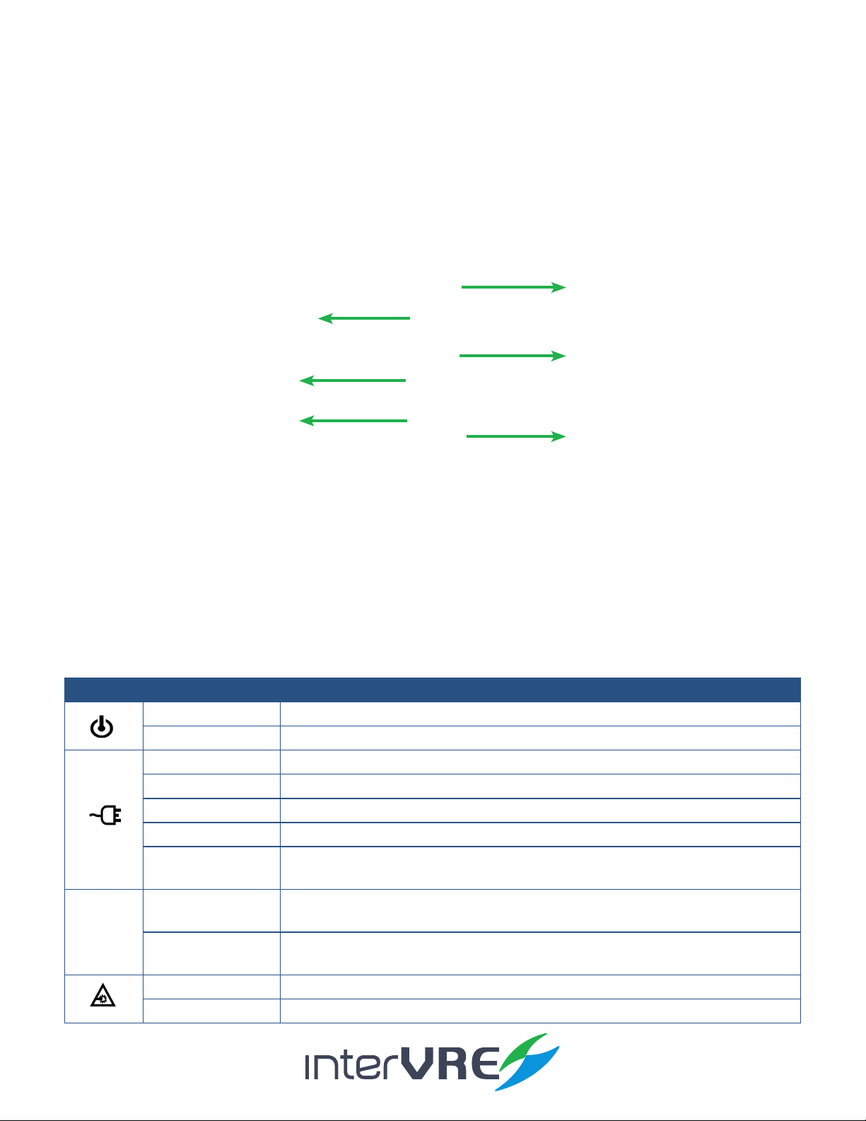
Table2.1LEDIndicatorDefinitions
2. Description
LED STATUS DESCRIPTION
Green On
O O, and unplugged in
Green Plugged in and baery is fully charged
Green (ashing) Baery is on charge
Red (ashing) Unplugged in, and baery is weak
Red Baery error
O • O
• Unplugged in, and baery level is above the ‘crical threshold’
Green Result status: success ( Current result of the applicaon does not exceed the
predened threshold)
Red Result status: failure (Current result of the applicaon exceeds the predened
threshold)
Green (ashing) Laser status LED, at least one module is transming an opcal signal
O No module is transming signal
Description
LED Indicators
Funcon Key
On/O Buon
Number Key
Direcon Key
Colour Touch Screen

IVR-6123 Handheld OTDR Test Set
10
2.1.3 Buttons
Table 2.2 describes the funcons of IVR-6123 Handheld OTDR Test Set’s buons.
Table2.2ButtonsDescription
Button Description
F1, F2, and F3 Funcon keys: Select the one sub menu from main menu displayed on the screen
Funcon keys: Switch the main menu
CANCEL X Cancel/Exit
OK √ OK/Conrm
• AB lines:
• Move AB lines right or le
• Move AB lines up or down
• Zoom:
• Zoom the curve horizontally
• Zoom the curve vercally
• Move:
• Move the screen right or le
• Move the screen up or down
AUTO Click to run the test automacally
• Switch mode:
• AB lines
• Zoom
• Move
Menu Back to main menu
Test • Long press: Switch the test mode
• Manual
• Real-me
• Short press: Start/Stop test
[1] Number key: Event list
?[3] Number key: Help informaon
INFO [4] Number key: Curve informaon
VFL [6] Number key: Open/Close VFL funcon
Open le
Save le
Restore the curve
On/O (Specic operaon informaon can be seen in Secon 5.1)
Description

IVR-6123 Handheld OTDR Test Set
11
2.2 Right Panel
2.2.1 RightPanelDiagram
Figure 2.2 IVR-6123 Handheld OTDR Test Set Right Panel View
2.2.2 Interfaces
Table 2.3 describes the interfaces of IVR-6123 Handheld OTDR Test Set.
Table2.3InterfacesDescription
DC Connector
USB Port (Type A)
RJ 45 Port
USB Port (Type B)
Interfaces Quantity Description
RJ-45 Port 1 Connect to Ethernet network
USB Host Ports 1• Connect USB memory drive;
• Connect keyboard;
• And connect mouse device, etc
Mini USB port 1Connect a USB cable for data transferring between the
device and a computer
Audio Output Port 1Connect headphone/microphone
DC Connector 1Connect A/C adapter
Description

IVR-6123 Handheld OTDR Test Set
12
2.3 Top Panel
Figure 2.3 IVR-6123 Handheld OTDR Test Set Top Panel View
Figure 2.4 IVR-6123 Handheld OTDR Test Set Top Panel View (PON)
2.4 BottomPanel
Figure 2.5 IVR-6123 Handheld OTDR Test Set Bottom Panel View
PM Interface
VFL Interface
SM Interface
PM Interface
VFL Interface
SM Interface
Baery Compartment
Description

IVR-6123 Handheld OTDR Test Set
13
3.1 EnvironmentalGuidelines
The IVR-6123 can work normally and stably under the severe environmental condion. Table 3.1
denes these environmental condions which are complied with the IVR-6123.
Table3.1EnvironmentalRanges
3.2 AdapterandBattery
3.2.1 AC/DCAdapter
AC/DC adapter can be plugged into any standard electrical socket but only for indoor using,
and can charge rechargeable Lithium-Ion baery.
Table3.2InputandOutputRequirement
3.2.2 RechargeableLithium-IonBattery
Rechargeable Lithium-Ion baery will supply the power for the device automacally when
the AC/DC adapter has been unplugged.
(Note: IVR-6123 Handheld OTDR Test Set will only work normally when the baery has been
installed in the baery compartment properly and the compartment cover has been locked
properly whether the device is using power source or not).
• The device work will not be aected by switching power supply between power source
and Lithium-Ion baery;
• Automacally charge when the device has been connected to power source;
• At least 8 connuous working hours under Bellcore TR-NWT-001138 standard.
3. Specifications
Voltage Current
Input 100-240VAC Max 1.6A
Output 15VDC 2A
Specifications
TemperatureRange HumidityRange
Operaonal -10°C � 50°C 0% � 95% (non-condensing)
Storage -40°C � 70°C 0% � 95% (non-condensing)

IVR-6123 Handheld OTDR Test Set
14
3.3 OtherPhysicalSpecifications
Table 3.3 describes other physical specicaons of IVR-6123 Handheld OTDR Test Set.
Table3.3OtherPhysicalSpecifications
Specifications
Specification Description
Power consumpon < 10W
Dimension Dimension (H×W×D) = 80mm x 135mm x 250mm;
Weight < 1.1kg

IVR-6123 Handheld OTDR Test Set
15
4.1 GeneralSafetyInformation
If the device has not been stored properly under the storage temperature range, the device’s
temperature must be guaranteed to reach the operaonal temperature before turn it on (Specic
environmental informaon can be found in Table 3.1).
4.2 LaserSafetyInformation
• Do not install or detach bres directly when a light source is acvated;
• Do not aempt to look directly into the bre, in case your eyes will be injured by opcal signal;
• The device is Class 1M laser product, complies with IEC 60825-1 Amendment: 2001 and 21 CFR
1040.10, hence invisible laser radiaon could be emied from opcal bre output port;
• Safety can be guaranteed by operang the device under a predictable and reasonable condions,
however using an opcal instrument to view the laser beam whether is diverged or not is potenally
hazardous, therefore do not aempt to use an opcal instrument to view the laser beam directly;
• When the laser safety light is ashing, which indicates at least one module is transming an
opcal signal, please check all modules working status, because the module which is transming
the signal might not be the one currently using.
4.3 ElectricalSafetyInformation
• Venlaon should be guaranteed around the device;
• Operang the device under the environment with highly inammable gas will cause a signicant
safety incident;
• To avoid lightning strike, do not aempt to operate the device during the thunderstorm,
parcularly when any part of the device surface (Cover, panels, etc.) has been damaged.
• Damage will be occurred if the input voltage or current of power source has exceeds the
maximum voltage or current limitaon, (Specic informaon for input requirement can be seen in
Secon 3.2 Adapter and Baery);
• If the device needs to be powered o completely, please make sure the adapter has been
unplugged, and removes the baeries;
• Replacement of any components or modules must be conducted under complete power o condion;
4. Safety Information
Safety

IVR-6123 Handheld OTDR Test Set
16
• Capacitors in the device may be sll under the charged condion even if the device has been
disconnected from its power supply;
• Only the person who is authorised by the rm can open the device without power o to do the
test, maintenance, and repair, and emergency workers must be present.
Safety

IVR-6123 Handheld OTDR Test Set
17
5.1 TurntheDeviceOnorOff
Power on/o buon: , Table 5.1 describes sepcic instrucon of turnning the device on or o.
Table5.1TurnOnorOffInstruction
5.2 InstallingorUpgradingtheApplications
All essenal applicaons have been preinstalled and congured at the factory. Also, extra
applicaons will be installed or exisng applicaons will be required to upgrade, when new
test modules have been purchased and installed, or newest version of the applicaon has been
purchased. Table 5.2 describes the hardware requirements for applicaons installing or upgrading.
Table5.2ApplicationInstallingorUpgradingHardwareRequirements
Applicaons can be installed or upgraded by the following steps:
• Turn on the computer and insert the installaon CD into the CD-ROM drive;
• Copy ‘Setup. exe’ into the USB memory sck;
• Plug the USB memory sck into IVR-6123 Handheld OTDR Test Set;
5. Installation of the Device
Installation
Function Description
Turn on Press on/o buon to turn on the device,
Sleep
• Press on/o buon for 5 seconds unl the device beeps once;
• Then release the on/o buon, the device will be hibernated;
• Then press on/o buon once, the device will be awaked; (Note: The device
only can be hibernated when all applicaons have been terminated),
Turn o Press on/o buon for 10 seconds unl device is powered o.
Name Quantity
CD for Installaon 1
Computer with USB Port 1
IVR-6123 Handheld OTDR Test Set 1
USB Memory Drive or USB Cable 1 or 1

IVR-6123 Handheld OTDR Test Set
18
• Select ‘System’ from main menu and enter ‘Explore’, then enter USB memory folder;
Figure 5.1 Explore
• Run ‘IVR-6123_OTDR _V1.0.0.1_SETUP.exe’ soware;
• Click ‘Setup’ buon.
5.3 InstallingaUSBKeyboardorMouse
USB keyboard and mouse are supported by IVR-6123 Network Test Plaorm, please follow the
following steps to install a keyboard or mouse:
• Plug the keyboard or mouse into the USB A type port which is placed on the right side of the
device;
• Keyboard or mouse will be detected and recognised automacally by the system. (Note: It is not
necessary to turn o the device before connecng the keyboard or mouse. The system will detect automacally.
Even a keyboard is connected, the touch screen keyboard will sll be displayed when operang under system.)
5.4 InstallingOpticalFibre
To guarantee the accuracy of test result, please follow the following instrucon to install the opcal bre:
• Please check the opcal bre which will be installed into the device has proper connector rstly.
Unmatchable connector will damage ferrule;
• Then do the bre end’s clearance: use coon bud with alcohol to wipe the opcal bre end gently
Installation

IVR-6123 Handheld OTDR Test Set
19
and soly, and use compressed air to dry it completely, then check the end visually and make sure
it clean; (Note: INTERVRE will not be responsible for damage which occurred from improper port’s clearance
or operaon.)
• Unscrew the dust cap of the interface connector;
• Plug the opcal bre’s connector into the device’s interface carefully, please ensure the opcal
bre’s end has not been touched with the outside of interface and other place. If the connector is
protrude type, please make sure the device’s interface is concave type, can t the connector;
• Push the connector into the device’s interface, and ensure the opcal bre has been fully
connected with the device. If the connector has screw sleeves, please ghten it up by screwing
the screw. However, do not over screw which could damage the bre and device. (Note: If the
opcal bre has not been installed properly, serious signal loss and light reecon will occur.)
Installation

IVR-6123 Handheld OTDR Test Set
20
6.1 FunctionSelect
IVR-6123 has 2 operaonal interface: OTDR and iOTA. Select and double click the icon to start an
interface. If ‘Auto start’ has been selected, the operaonal interface will be as same as previous
when turn on the device next me.
Figure 6.1 Function Select
6.2 OTDRInterface
OTDR interface is comprised by 4 parts: Status bar; Curve window; Event informaon; and Main
menu.
Figure 6.2 OTDR Interface
6. Main Interface
Interface
Status Bar
Event Informaon
Curve Window
Main Menu
Table of contents
Other intervre Test Equipment manuals


