manuals.online logo
Brands
  1. Home
  2. •
  3. Brands
  4. •
  5. IntesisBox
  6. •
  7. Recording Equipment
  8. •
  9. IntesisBox PA-AC-MBS-1 User manual

IntesisBox PA-AC-MBS-1 User manual

Interfaz PA-AC-MBS-1 FW:2.3
Interface PA-AC-MBS-1 FW:2.3
1 / 2
© Intesis Software S.L.U. - Todos los derechos reservados/ All rights reserved
IntesisBox es una marca registrada de / is a registred trademark of Intesis Software SLU
La información en este documento puede variar sin previo aviso. / This information is subject to change without notice.
Doc. Rev 1.0
URL
email
Phone
http://www.intesisbox.com
info@intesisbox.com
+34 938047134
•Esta interfaz debe ser instalada por personal técnico
acreditado (electricista, instalador o personal técnico
cualificado) y siguiendo todas las instrucciones de
seguridad.
•La interfaz debe ser instalada en una ubicación con acceso
restringido.
•Antes de manipular en el interior del aire acondicionado,
asegúrese de que está completamente desconectado de la
red eléctrica.
•En caso de instalación mural del interfaz junto a la unidad
interior del aire acondicionado, fije la interfaz de forma
segura siguiendo las instrucciones del diagrama de abajo.
•En caso de instalación de la interfaz en el interior de la
unidad interior de aire acondicionado, fije la interfaz y los
cables de comunicación preferiblemente en algún punto de
la carcasa de plástico de forma que no interfieran al libre
movimiento de partes móviles y alejados al máximo de
tubos conductores de líquidos y cables eléctricos.
•This interface must be installed by accredited technical
personnel (electrician, installer or qualified technical
personnel) and they must follow all the safety instructions.
•This interface must be installed in an acces restricted
location
•Before manipulating the AC indoor unit, make sure it is
completely disconnected from Mains Power.
•In case of wall mounting of the interface next to the AC
indoor unit, attach the interface safely following the
instructions of the diagram below.
•In case of installation of the interface inside the AC indoor
unit, attach the interface and communication cables
preferably to any proper point of the plastic cover of each
unit and take care to not block free movement of mobile
parts. Locate them as far as possible from pipes containing
liquids and power cables.
•Desconecte el aire acondicionado de la red eléctrica.
•Fije la interfaz a la pared junto a la unidad interior del aire
acondicionado siguiendo las instrucciones del diagrama de
abajo o dentro de la unidad interior del aire acondicionado
(respete las instrucciones de seguridad anteriores).
•Conecte el extremo largo del cable suministrado al conector
CN-CNT de la unidad interior de A.A. y el otro extremo al
conector AC Unit de la pasarela IntesisBox.
•Conecte el bus EIA-485 al conector EIA485 de la interfaz.
Respete la polaridad.
•Tape la unidad interior del aire acondicionado y vuelva a
conectarla a la red eléctrica.
•Siga las instrucciones del Manual de Usuario para la
configuración y puesta en servicio de la interfaz.
•Siga las instrucciones de la página siguiente para
configurar la interfaz a través de los micro interruptores.
•Disconnect the air conditioning from the Mains Power.
•Attach the interface next to the AC indoor unit (wall
mounting) following the instructions of the diagram below or
install it inside the AC indoor unit (respect the safety
instructions given above).
•Connect the long end of the supplied cable in the CN-CNT
connector of the AC indoor unit and the other end into the
“AC Unit” connector of our gateway.
•Connect the EIA-485 bus to the connector EIA485 of the
interface.
•Close the AC indoor unit and reconnect it to Mains Power.
•Follow the instructions on the User’s Manual to configure
and commission the interface.
•Follow the instructions of the next page to configure the
interface through on-board DIP-switches.
WARNING
ATENCIÓN
Siga atentamente estas instrucciones de seguridad e
instalación. Un manejo inadecuado puede ocasionar daños
graves para su salud y daños irreparables en la interfaz y/o
en la unidad interior del aire acondicionado.
Follow carefully this safety and installation instructions. Not
proper work may lead to a serious damage for your health and
may harm seriously the interface and/or the AC indoor unit.
IMPORTANTE: La ampliación o acortamiento del cable
de conexión que se incluye con el interfaz puede provocar un
funcionamiento incorrecto. Mantenga el cable de conexión lo
más alejado posible del cableado eléctrico y del cable de
tierra, no los enrolle juntos.
IMPORTANT: Extending or shortening the connecting
cable included with the interface may cause it to malfunction.
Keep the connecting cable as far away as possible from
electrical wires and ground wire. Do not bundle them together.
El Manual de Usuario está disponible en:
https://www.intesisbox.com/en/panasonic-modbus-ac-pa-ac-mbs-1/gateway/
The User’s Manual is available at:
https://www.intesisbox.com/en/panasonic-modbus-ac-pa-ac-mbs-1/gateway/
Instrucciones de seguridad
Safety intructions
Instrucciones de instalación
Installation instructions
CN-CNT
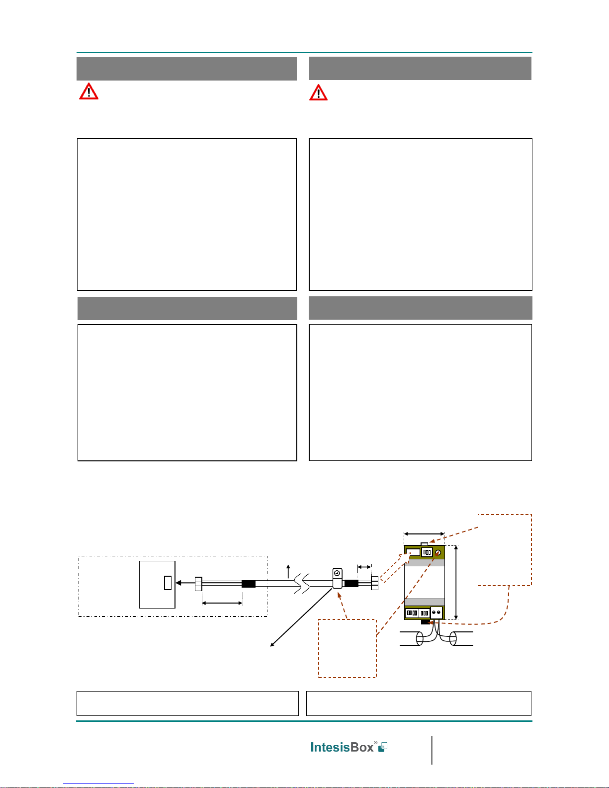
Unidad interior aire acondicionado
AC indoor unit
Tarjeta control interior
Internal control board
200 mm / 7.9”
40 mm / 1.6”
Cable de conexión
suministrado con el
interfaz.
Connection cable
supplied with the
interface.
Tornillo de fijación
Fixing screw
90 mm / 3.5”
IntesisBox®
DK-AC-MBS-1
MODBUS RTU
EIA-485
Bus
EIA485
A B
AC Unit
53 mm / 2.1”
Para fijación mural,
extraiga hacia fuera
las grapas superior
e inferior hasta oir
el "click".
For wall mounting,
extract the upper
and lower staples
until you hear the
"click".
Use este agujero
para fijar el cable con
la grapa y tornillo
suministrados.
Use this hole to
attach the cable
using the staple and
screw provided.
Interfaz PA-AC-MBS-1 FW:2.3
Interface PA-AC-MBS-1 FW:2.3
2 / 2
© Intesis Software S.L.U. - Todos los derechos reservados/ All rights reserved
IntesisBox es una marca registrada de / is a registred trademark of Intesis Software SLU
La información en este documento puede variar sin previo aviso. / This information is subject to change without notice.
Doc. Rev 1.0
URL
email
Phone
http://www.intesisbox.com
info@intesisbox.com
+34 938047134
IMPORTANTE: Es necesario resetear el equipo (quitar tensión) tras modificar
la configuración de los micro interruptores para que ésta se aplique.
IMPORTANT: It is required to reboot or power cycle the interface every time
the DIP switch configuration changes.
SW1-P1..4
Descripción
Description
SW3-P7..8
SW4-P3
Descripción
Description
SW4-P1..2-4
Descripción
Description
La unidad de A.A. no tiene modo ventilación
AC unit does not have fan mode
2400bps
Los valores de temperatura en los registros Modbus se
representan en decigrados (x10)
Temperature values in Modbus register are represented in
decidegrees (x10)
La unidad de A.A. tiene modo ventilación (Valor p. defecto)
AC unit has fan mode (Default value)
4800bps
Los valores de temperatura en los registros Modbus se
representan en grados (x1) (Valor por defecto).
Temperature values in Modbus register are represented in degrees
(x1) (Default value).
La unidad de A.A. no tiene lamas horizontales
AC unit does not have horizontal vanes
9600bps
(Valor por defecto
default value)
Los valores de temperatura en los registros Modbus se
representan en grados Fahrenheit
Temperature values in Modbus register are represented in
Fahrenheit degrees
La unidad de A.A. tiene lamas horizontales (Valor defecto)
AC unit does has horizontal vanes (Default value)
19200bps
Los valores de temperatura en los registros Modbus se
representan en grados Celsius (Valor por defecto)
Temperature values in Modbus register are represented in Celsius
degrees (Default value)
Mantenga el switch en esta posición (Valor por defecto)
Keep the switch into this position (Default value)
38400bps
Resistencia interna de 120Ωconectada al bus EIA-485
Internal termination resistor of 120Ω connected to EIA-485 bus
No cambie el switch a esta posición (no aplicable)
Do not turn the switch into this position (not applicable)
57600bps
Bus EIA-485 sin resistencia de terminación (Valor por defecto).
EIA-485 bus without termination resistor (Default value).
Mantenga el switch en esta posición (Valor por defecto)
Keep the switch into this position (Default value)
76800bps
No cambie el switch a esta posición (no aplicable)
Do not turn the switch into this position (not applicable)
115200bps
Dirección de esclavo Modbus - Modbus Slave address
Direcc
Add
SW3-P1..6
Direcc
Add
SW3-P1..6
Direcc
Add
SW3-P1..6
Direcc
Add
SW3-P1..6
Direcc
Add
SW3-P1..6
Direcc
Add
SW3-P1..6
0
11
22
33
44
55
1
12
23
34
45
56
2
13
24
35
46
57
3
14
25
36
47
58
4
15
26
37
48
59
5
16
27
38
49
60
6
17
28
39
50
61
7
18
29
40
51
62
8
19
30
41
52
63
9
20
31
42
53
10
21
32
43
54
Configuración del número de esclavo Modbus y baudios.
Configuration of Modbus Slave number and baud rate.
Configuración de los baudios, magnitud temperatura (x1/x10), unidades de
temperatura (ºC/ºF) y resistencia de terminación de EIA-485.
Configuration of baud rate, temperature magnitude (x1/x10), temperature
units (Cº/Fº) and termination resistor for EIA-485.
IntesisBox®
PA-AC-MBS-1
EIA485
A B
AC Unit
SW3
SW4
SW1
1 2 3 4
SW1
1 2 3 4
SW4
1 2 3 4 5 6 7 8
SW3
ON SAB
ON SAB
ON SAB
ON SAB
ON SAB
ON SAB
ON SAB
ON SAB
ON SAB
Configuración por micro interruptores
Configuration through DIP switches
ON SAB
ON SAB
ON SAB
ON SAB
ON SAB
ON SAB
ON SAB
ON SAB
ON SAB
ON SAB
ON SAB
ON SAB
ON SAB
ON SAB
ON SAB
ON SAB
ON SAB
ON SAB
ON SAB
ON SAB
ON SAB
ON SAB
ON SAB
ON SAB
ON SAB
ON SAB
ON SAB
ON SAB
ON SAB
ON SAB
ON SAB
ON SAB
ON SAB
ON SAB
ON SAB
ON SAB
ON SAB
ON SAB
ON SAB
ON SAB
ON SAB
ON SAB
ON SAB
ON SAB
ON SAB
ON SAB
ON SAB
ON SAB
ON SAB
ON SAB
ON SAB
ON SAB
ON SAB
ON SAB
ON SAB
ON SAB
ON SAB
ON SAB
Configuración de la función de ventilación y lamas horizontales
Selection of the fan function available and horizontal vanes present
ON
ON
ON
ON
ON
ON
ON
ON
ON
ON
ON
ON
ON
ON
ON
ON
ON
ON
ON
ON
ON
ON
AC UNIT
ON
ON
ON
ON
ON
ON
ON
ON

Other IntesisBox Recording Equipment manuals

IntesisBox DK-RC-MBS-1 User manual

IntesisBox

IntesisBox DK-RC-MBS-1 User manual

IntesisBox TO-RC-BAC-1 User manual

IntesisBox

IntesisBox TO-RC-BAC-1 User manual

IntesisBox MH-RC-MBS-1 User manual

IntesisBox

IntesisBox MH-RC-MBS-1 User manual

IntesisBox PA-RC2-BAC-1 User manual

IntesisBox

IntesisBox PA-RC2-BAC-1 User manual

IntesisBox PA-RC2-BAC-1 User manual

IntesisBox

IntesisBox PA-RC2-BAC-1 User manual

IntesisBox MH-RC-BAC-1 User manual

IntesisBox

IntesisBox MH-RC-BAC-1 User manual

IntesisBox PA-AW2-MBS-1 User manual

IntesisBox

IntesisBox PA-AW2-MBS-1 User manual

IntesisBox PA-AW-MBS-1 User manual

IntesisBox

IntesisBox PA-AW-MBS-1 User manual

IntesisBox HA-AC-KNX-16 User manual

IntesisBox

IntesisBox HA-AC-KNX-16 User manual

IntesisBox SM-RC-MBS-1 User manual

IntesisBox

IntesisBox SM-RC-MBS-1 User manual

IntesisBox PA-AC-BAC-1 Setup guide

IntesisBox

IntesisBox PA-AC-BAC-1 Setup guide

IntesisBox PA-RC2-WMP-1 User manual

IntesisBox

IntesisBox PA-RC2-WMP-1 User manual

IntesisBox TO-RC-MBS-1 User manual

IntesisBox

IntesisBox TO-RC-MBS-1 User manual

IntesisBox FJ-RC-WMP-1 User manual

IntesisBox

IntesisBox FJ-RC-WMP-1 User manual

IntesisBox ME-AC-BAC-1L User manual

IntesisBox

IntesisBox ME-AC-BAC-1L User manual

IntesisBox DK-RC-MBS-1 User manual

IntesisBox

IntesisBox DK-RC-MBS-1 User manual

IntesisBox MH-RC-MBS-1 User manual

IntesisBox

IntesisBox MH-RC-MBS-1 User manual

IntesisBox PA-RC2-MBS-1 User manual

IntesisBox

IntesisBox PA-RC2-MBS-1 User manual

IntesisBox KNX Series User manual

IntesisBox

IntesisBox KNX Series User manual

IntesisBox HI-AW-KNX-1 User manual

IntesisBox

IntesisBox HI-AW-KNX-1 User manual

IntesisBox LG-RC-WMP-1 User manual

IntesisBox

IntesisBox LG-RC-WMP-1 User manual

IntesisBox IS-IR-WMP-1 User manual

IntesisBox

IntesisBox IS-IR-WMP-1 User manual

IntesisBox DK-AC-WMP-1 User manual

IntesisBox

IntesisBox DK-AC-WMP-1 User manual

IntesisBox PA-AW-KNX-1 User manual

IntesisBox

IntesisBox PA-AW-KNX-1 User manual

Popular Recording Equipment manuals by other brands

TT Systems Tele-Recorder VTR-700 user manual

TT Systems

TT Systems Tele-Recorder VTR-700 user manual

QRS PNO3WB instructions

QRS

QRS PNO3WB instructions

Aiphone JKTLI Operation manual

Aiphone

Aiphone JKTLI Operation manual

Yellowtec PUC2 manual

Yellowtec

Yellowtec PUC2 manual

Hach SD900 user manual

Hach

Hach SD900 user manual

Tascam MMR-8 Owner's manual update

Tascam

Tascam MMR-8 Owner's manual update

Elster PFA technical information

Elster

Elster PFA technical information

Voiceye Mate VMP-100 user manual

Voiceye

Voiceye Mate VMP-100 user manual

Sentiotec STP-INFACE-T instruction manual

Sentiotec

Sentiotec STP-INFACE-T instruction manual

Sanyo VZU-485 instruction manual

Sanyo

Sanyo VZU-485 instruction manual

Akai HV 1 Service manual

Akai

Akai HV 1 Service manual

Brigade MDR 500 Series Installation and operation guide

Brigade

Brigade MDR 500 Series Installation and operation guide

Tubbutec OrganDonor installation manual

Tubbutec

Tubbutec OrganDonor installation manual

Rohde & Schwarz HAMEG Instruments HO740 FITTING INSTRUCTION

Rohde & Schwarz

Rohde & Schwarz HAMEG Instruments HO740 FITTING INSTRUCTION

Hach MP-Dock user manual

Hach

Hach MP-Dock user manual

Philips CDR950BK99 Instructions for use

Philips

Philips CDR950BK99 Instructions for use

Fava PT6 user manual

Fava

Fava PT6 user manual

Sound Devices CL-12 user guide

Sound Devices

Sound Devices CL-12 user guide

manuals.online logo
manuals.online logoBrands
  • About & Mission
  • Contact us
  • Privacy Policy
  • Terms and Conditions

Copyright 2025 Manuals.Online. All Rights Reserved.