manuals.online logo
Brands
  1. Home
  2. •
  3. Brands
  4. •
  5. IntesisBox
  6. •
  7. Server
  8. •
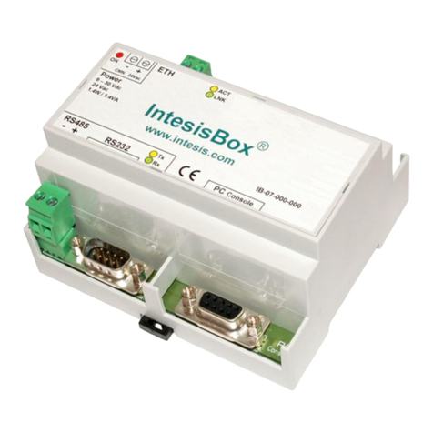
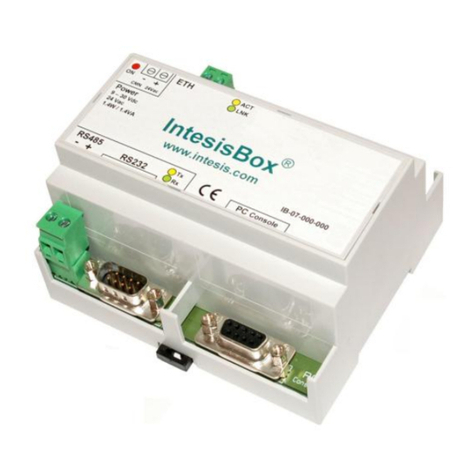
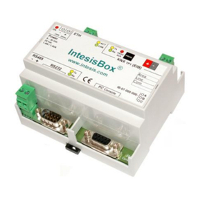
  9. IntesisBox Modbus Server-Mitsubishi Heavy Industries AC User manual

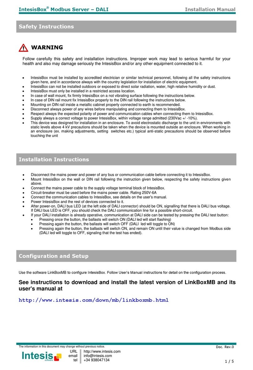
IntesisBox Modbus Server-Mitsubishi Heavy Industries AC User manual

Doc. Rev. 2
Installation Manual
URL
email
tel
http://www.intesis.com
[email protected]m
+34 938047134
1 / 4
This information is subject to change without notice.
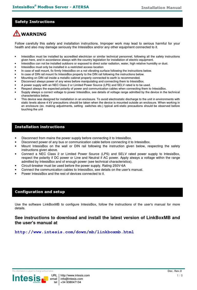
IntesisBox®Modbus Server –Mitsubishi Heavy Industries AC
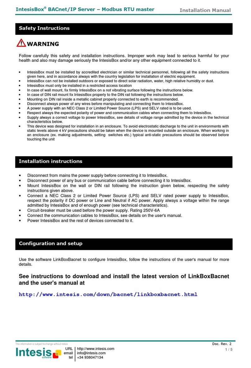
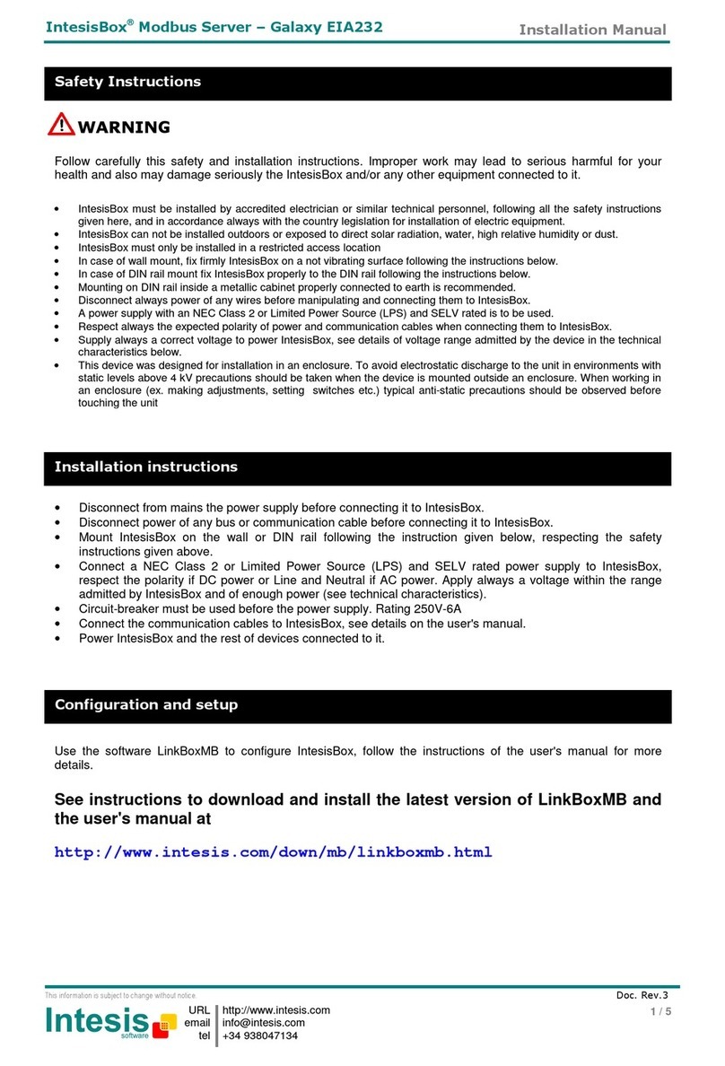
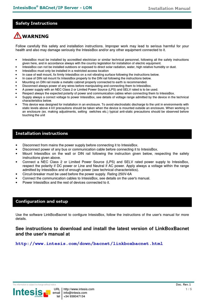
IntesisBox must be installed by accredited electrician or similar technical personnel, following all the safety instructions
given here, and in accordance always with the country legislation for installation of electric equipment.
IntesisBox can not be installed outdoors or exposed to direct solar radiation, water, high relative humidity or dust.
IntesisBox must only be installed in a restricted access location
In wall mount, fix firmly IntesisBox on a not vibrating surface following the instructions below.
Mounting inside a metallic cabinet properly connected to earth is recommended.
Disconnect always power of any wires before manipulating and connecting them to IntesisBox.
Respect always the expected polarity of power and communication cables when connecting them to IntesisBox.
Supply always a correct voltage to power IntesisBox, see details of voltage range admitted by the device in the technical
characteristics below.
This device was designed for installation in an enclosure. To avoid electrostatic discharge to the unit in environments with
static levels above 4 kV precautions should be taken when the device is mounted outside an enclosure. When working in
an enclosure (ex. making adjustments, setting switches, etc.) typical anti-static precautions should be observed before
touching the unit.
Safety Instructions
WARNING
Follow carefully this safety and installation instructions. Improper work may lead to serious harmful for your
health and also may damage seriously the IntesisBox and/or any other equipment connected to it.
Use the software LinkBoxMB to configure IntesisBox, follow the instructions of the user's manual for more
details.
See instructions to download and install the latest version of LinkBoxMB and
the user's manual at
http://www.intesis.com/down/mb/linkboxmb.html
Configuration and setup
Disconnect the mains power and power of any bus or communication cable before connecting it to
IntesisBox.
Mount IntesisBox following the instructions given below, respecting the safety instructions given above.
Connect the mains power cable to the supply voltage terminal block of IntesisBox.
Circuit-breaker must be used before the mains power cable. Rating 250V-6A
Connect the communication cables to IntesisBox, see details on the user's manual.
Power IntesisBox and the rest of devices connected to it.
Installation instructions
Doc. Rev. 2
Installation Manual
URL
email
tel
http://www.intesis.com
[email protected]m
+34 938047134
2 / 4
This information is subject to change without notice.
IntesisBox®Modbus Server –Mitsubishi Heavy Industries AC
Use the holes to fix the box in the wall using screws. Use the template below for the wall holes:
Wall mount
Wall mount
Dimensions
External dimensions.
215 mm
167 mm
61 mm
Top view of the box
Ø 5 mm
195 mm
138 mm
10 mm
15 mm
Doc. Rev. 2
Installation Manual
URL
email
tel
http://www.intesis.com
[email protected]m
+34 938047134
3 / 4
This information is subject to change without notice.
IntesisBox®Modbus Server –Mitsubishi Heavy Industries AC
Connections and indications
________________________________________________________________________________________
Notes:
1. Mains power conection: 230VAC (see sectionTechnical Characteristics). The device provides switch and a protection fuse. Use the supplied cable with IntesisBox (1,6m).
2. Console conection: Connect the supplied console cable with IntesisBox (1.8 meters long, standard DB9 male-DB9 female) between your PC and the console port of the
device. Use the software LinkBoxMB to configure IntesisBox. See the user's manual for details.
3. Modbus connection: IntesisBox allows different connection types: Modbus TCP (ETH port), Modbus RTU EIA485 (C1 port), or Modbus RTU EIA232 (C2 port), this must
be configured within LinkBoxMB software.
Modbus TCP: Connect the cable coming from the Modbus TCP master device to the connector ETH of IntesisBox, use a crossover ethernet CAT5 cable if
connecting directly to the Modbus TCP master device, or an straight ethernet CAT5 cable if connecting to a switch or hub of the LAN of the building. If
connecting using the LAN of the building contact the network administrator and make sure that TCP/IP traffic and the TCP port used (502 by default) are
allowed through all the LAN path.
Modbus RTU EIA485: Connect the EIA485 bus to the connector Modbus RTU EIA485 of IntesisBox (C1). Respect the polarity. Remember the
characteristics of the standard EIA485 bus: maximum distance of 1200 meters, maximum 32 device connected, and a 120 ohms terminator resistor in
each end of the bus. IntesisBox comes with an internal bus byasing circuit which incorporates internal bus terminator resistor, and thus if you connect
IntesisBox in one end of the bus then it is not necessary to install additional 120 ohms resistor in that end.
Modbus RTU EIA232: Connect the serial EIA232 cable coming from the Modbus RTU master device to the Modbus RTU EIA232 connector of IntesisBox
(C2), this is a male DB9 connector (DTE) in which only lines TX, RX and GND are used, see pinout details in the user's manual. Respect the maximum
distance of 15 meters for this EIA232 line.
4. A-B connection: Connect the SuperLink®bus coming from the Mitsubishi Heavy Industries AC to the conector A-B of IntesisBox. Recpect the polarity, and consult your
distributor for more details.
5. The device provides a “RESET” button.
6. The device provides a selector to choose the SuperLink® bus type. If it belong to the OLD version (SuperLink®1), or to the NEW version (SuperLink®2).
7. OP led: indication that the device is operative.
8. ERROR led: the led is ON when there is a communication error.
9. HOST led: the led is blinking when there is connectivity between the two circuits that compose IntesisBox.
10. PAC led: the led is blinking when there is activity in the SuperLink® bus, ie when there is communication between IntesisBox and AC system.
Device front view
Device back view
1
2
3
4
5
6
7
8
9
10
Doc. Rev. 2
Installation Manual
URL
email
tel
http://www.intesis.com
[email protected]m
+34 938047134
4 / 4
This information is subject to change without notice.
IntesisBox®Modbus Server –Mitsubishi Heavy Industries AC
Enclosure
Industrial sheet metal.
Size: 215mm x 167mm x 61mm.
Weight: 2.025 Kg
Color
Gray metalized.
Power
100 to 240VAC~
50 to 60Hz
5W max.
Power connector: C14 (male) 1
Fuse
250V
1.5A
Dimensions: 20x5mm
Terminal wiring
(for low-voltage
signals)
Per terminal: solid wires or stranded wires (twisted or with ferrule)
1 core: 0.75 … 1.25mm2
2 cores: 0.75 … 1.25mm2
3 cores: not permitted
Mounting
Wall
Modbus TCP port
1 x Ethernet 10Base-T (RJ45).
Modbus RTU ports
1 x Serial EIA232 (DB9 male DTE). SELV
1 x Serial EIA485 (Plug-in screw terminal block 2 poles). SELV
A-B port
1 x Superlink®terminals (Plug-in screw terminal block 2 poles “A”
“B”). SELV
LED indicators
2 x Ethernet port link and activity (LNK, ACT).
4 x MHI Interface (OP, ERR, HOST, PAC)
Push buttons
1 x Reset Device
Selectors
1 x SLK selector
Console port
EIA232. (DB9 female DCE). SELV
Configuration
Via console port. 2
Firmware
Allows upgrades via console port.
Operational
temperature range
0°C to +40°C
Operational
humidity range
5% to 95%, non condensing
Protection
IP20 (IEC60529).
RoHS conformity
Compliant with RoHS directive (2002/95/CE).
Norms and
standards
CE conformity to EMC directive (2004/108/EC) and Low-voltage
directive (2006/95/EC)
EN 61000-6-2
EN 61000-6-3
EN 60950-1
EN 50491-3
1
A power cable with connector C14 male 1.6 meters long is supplied with the device.
2
Standard cable DB9male-DB9female 1.8 meters long is supplied with the device for connection to a PC COM port for configuring
and monitoring the device. The configuration software, compatible with Windows®operating systems, is also supplied.
Technical characteristics

Other IntesisBox Server manuals

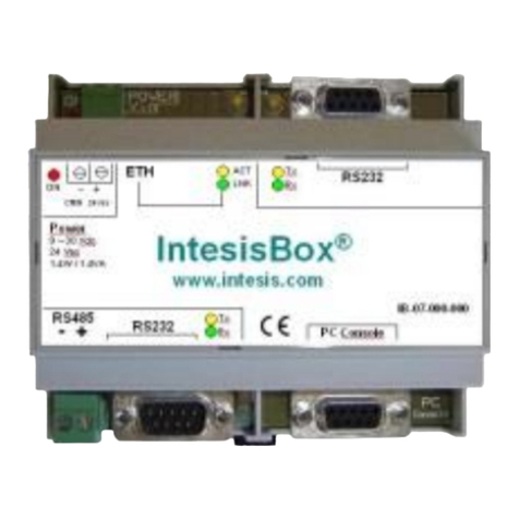
IntesisBox BACnet/IP Server–Modbus TCP master User manual

IntesisBox

IntesisBox BACnet/IP Server–Modbus TCP master User manual

IntesisBox Modbus Server-ATERSA User manual

IntesisBox

IntesisBox Modbus Server-ATERSA User manual

IntesisBox IBOX-MBS-KNX-100 User manual

IntesisBox

IntesisBox IBOX-MBS-KNX-100 User manual

IntesisBox Modbus Server-AlgoRex User manual

IntesisBox

IntesisBox Modbus Server-AlgoRex User manual

IntesisBox Modbus Server-Cerberus ISO1745 User manual

IntesisBox

IntesisBox Modbus Server-Cerberus ISO1745 User manual

IntesisBox BACnet/IP Server-SUNWAYS User manual

IntesisBox

IntesisBox BACnet/IP Server-SUNWAYS User manual

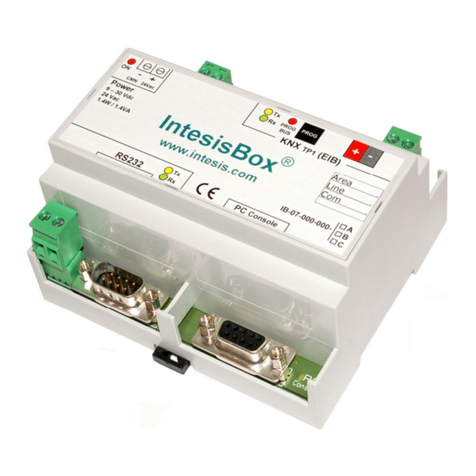
IntesisBox KNX TP-1 (EIB) User manual

IntesisBox

IntesisBox KNX TP-1 (EIB) User manual

IntesisBox IBOX-ASCII-KNX User manual

IntesisBox

IntesisBox IBOX-ASCII-KNX User manual

IntesisBox Modbus Server-Algorinet User manual

IntesisBox

IntesisBox Modbus Server-Algorinet User manual

IntesisBox MH-RC-BAC-1 User manual

IntesisBox

IntesisBox MH-RC-BAC-1 User manual

IntesisBox IBMBSKNX1000000 User manual

IntesisBox

IntesisBox IBMBSKNX1000000 User manual

IntesisBox ASCII Server-KNX User manual

IntesisBox

IntesisBox ASCII Server-KNX User manual

IntesisBox Modbus Server-Galaxy EIA232 User manual

IntesisBox

IntesisBox Modbus Server-Galaxy EIA232 User manual

IntesisBox BACnet/IP Server-DALI User manual

IntesisBox

IntesisBox BACnet/IP Server-DALI User manual

IntesisBox Modbus Server-FIDELIO TCP/IP User manual

IntesisBox

IntesisBox Modbus Server-FIDELIO TCP/IP User manual

IntesisBox ASCII Server-LON User manual

IntesisBox

IntesisBox ASCII Server-LON User manual

IntesisBox IBOX-MBS-TCP2RTU User manual

IntesisBox

IntesisBox IBOX-MBS-TCP2RTU User manual

IntesisBox IBBACMEB0100000 User manual

IntesisBox

IntesisBox IBBACMEB0100000 User manual

IntesisBox IBOX-ASCII-BAC-A User manual

IntesisBox

IntesisBox IBOX-ASCII-BAC-A User manual

IntesisBox BACnet/IP Server-FIDELIO TCP/IP User manual

IntesisBox

IntesisBox BACnet/IP Server-FIDELIO TCP/IP User manual

IntesisBox Modbus Server-FC330A User manual

IntesisBox

IntesisBox Modbus Server-FC330A User manual

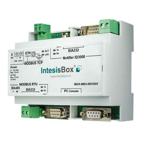
IntesisBox BACnet/IP Server-Notifier ID3000 User manual

IntesisBox

IntesisBox BACnet/IP Server-Notifier ID3000 User manual

IntesisBox BACnet/IP Server-LON User manual

IntesisBox

IntesisBox BACnet/IP Server-LON User manual

IntesisBox IBMBSMEB0100000 User manual

IntesisBox

IntesisBox IBMBSMEB0100000 User manual

Popular Server manuals by other brands

GDC SR-1000 STANDALONE INTEGRATED MEDIA BLOCK user manual

GDC

GDC SR-1000 STANDALONE INTEGRATED MEDIA BLOCK user manual

Digital Equipment VAX 6000-400 installation guide

Digital Equipment

Digital Equipment VAX 6000-400 installation guide

IBM 7380E1U datasheet

IBM

IBM 7380E1U datasheet

Nvidia RTX Service manual

Nvidia

Nvidia RTX Service manual

Axis 241Q Blade installation guide

Axis

Axis 241Q Blade installation guide

IBM xSeries 366 Problem determination and service guide

IBM

IBM xSeries 366 Problem determination and service guide

Mediastar Evolution 775 quick start guide

Mediastar Evolution

Mediastar Evolution 775 quick start guide

Moxa Technologies NPort 5600-8-DT user manual

Moxa Technologies

Moxa Technologies NPort 5600-8-DT user manual

Compaq ProLiant 1200 manual

Compaq

Compaq ProLiant 1200 manual

Polycom DOC2558B Hardware guide

Polycom

Polycom DOC2558B Hardware guide

AMX MAX-HT04 installation guide

AMX

AMX MAX-HT04 installation guide

IBM System x3400 M3 Types 7378 Product guide

IBM

IBM System x3400 M3 Types 7378 Product guide

NEC N8100-1056F user guide

NEC

NEC N8100-1056F user guide

Supermicro MicroBlade MBE-628L-416 user manual

Supermicro

Supermicro MicroBlade MBE-628L-416 user manual

Lantronix Micro125 user guide

Lantronix

Lantronix Micro125 user guide

Oracle SPARC T5-2 Service manual

Oracle

Oracle SPARC T5-2 Service manual

Dell PowerEdge M630p owner's manual

Dell

Dell PowerEdge M630p owner's manual

Balcrank 3110-012 Operation, installation, maintenance and repair guide

Balcrank

Balcrank 3110-012 Operation, installation, maintenance and repair guide

manuals.online logo
manuals.online logoBrands
  • About & Mission
  • Contact us
  • Privacy Policy
  • Terms and Conditions

Copyright 2025 Manuals.Online. All Rights Reserved.