Intuitive Circuits GeoStamp+ User manual

GeoStamp+®
Copyright © 2010 Intuitive Circuits, LLC
GPS on-screen composite video overlay
Version 1.02

Description
GeoStamp+®is an on-screen composite video overlay device that overlays GPS
(Global Positioning System) latitude, longitude, heading (track), speed, altitude,
date, and time onto any incoming NTSC or PAL composite video source such as a
color video camera. In addition to displaying GPS information, GeoStamp+®can
also display a user defined message as well as real-time distance and bearing to a
user defined waypoint.
GeoStamp+®produces a self-generated screen if no video input source is available.
All NMEA 0183 compatible GPS receivers are supported.
Specifications
Dimensions: 4 1/4" x 3 1/2" x 1 1/4"
Weight: 8.0 oz.
RoHS compliant: Yes
Input voltage: 7.0 to 14.0 volts DC (150 ma max.)
DC plug: 2.1 mm x 5.5 mm, center tip positive
Operating temperature: -40C to +85C (extended temperature range standard)
Video format: Composite video
Video level: 1 volt peak to peak
Video impedance: Input 75 ohm, output 75 ohm resistively terminated
GPS input: NMEA 0183. 4,800 - 38,400 baud. GPRMC and
GPGGA sentences.
Speed format: MPH, KPH, and knots
Altitude format: Feet and meters
Heading (track) format: Compass cardinal points (e.g. NW) and degrees
Time format: UTC with user time zone adjustment
Date format: mm/dd/yy and dd/mm/yy
User custom message length: 10 characters
2figure 1

3
Connections
GeoStamp+®has four connectors (see figure 1).
Connector Hookup
VIDEO IN (optional) • Attach noise free NTSC or PAL composite video source
• Leave disconnected for self-generated video output
VIDEO OUT • Attach to video monitor, DVR, video transmitter, etc.
GPS RECEIVER • Pin 2 - Attaches to GPS receiver serial output
• Pin 5 - Attaches to GPS receiver serial ground
DC IN • +7.0 to +14 volts DC
• 2.1 mm x 5.5 mm DC coax plug, center tip positive
DIP Switch Configuration
GeoStamp+®comes configured for NTSC video format and 4,800 baud GPS
operation. To reconfigure these settings GeoStamp+®has 4 internal dip switches.
To access the dip switches disconnect all cables from the GeoStamp+®unit then
remove the 2 screws from the rear of the enclosure. After removing the rear panel
and bezel the circuit board will slide out.
DIP # Description
1 & 2 GPS RS-232 baud rate
DIP 1 DIP 2 Baud
OFF OFF 4,800
OFF ON 9,600
ON OFF 19,200
ON ON 38,400
3 NTSC or PAL video format
OFF = NTSC
ON = PAL
4 Firmware flash update
OFF = Normal operation
ON = Firmware flash mode
Note: DIP switch inputs are only checked during power-up.

4
On-Screen Menu Configuration
At any time press the "MENU" button to enter the on-screen menu configuration.
The "UP", "DOWN", and "ENTER" buttons move the cursor and change the
settings. All configuration information is stored in non-volatile memory so
information is retained even with loss of power to GeoStamp+®.
Main Menu:
Menu Option Action / Setting
Enable GPS Overlay • ON - Display the overlay text
• OFF - Pass video through without displaying the
overlay text
Display Options Menu... Display the Options Menu
Field Formatting Menu... Display the Field Formatting Menu
Save Changes and Exit Save changes and exit the Main Menu
Discard Changes and Exit Discard changes and exit the Main Menu
Display Options Menu:
Menu Option Action / Setting
Screen Layout Select an on-screen GPS field layout format
• Standard - Fields are displayed on the top and bottom
of the screen
• Top - Fields are displayed on the top of the screen
• Bottom - Fields are displayed on the bottom of the screen
• Left - Fields are displayed on the left side of the screen
• Right - Fields are displayed on the right side of the screen
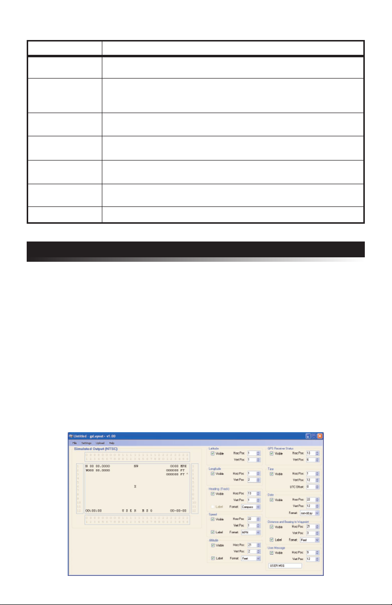
• Custom - Field layout is configured via gsLayout+ application
Backgnd Frame • ON - Draw a background frame behind the overlay text
• OFF - Do not draw a background frame behind the overlay text
Show Status • ON - Display the GPS receiver status on-screen
• OFF - Do not display the GPS receiver status on-screen
Show Altitude • ON - Display altitude on-screen
• OFF - Do not display altitude on-screen
Show Ranging • ON - Display distance and bearing to waypoint on-screen
• OFF - Do not display distance and bearing to waypoint on-screen
Show User Msg • ON - Display the user defined message on-screen
• OFF - Do not display the user defined message on-screen
User Message Enter an optional 10 character on-screen message
• MENU button to decrement cursor position
• ENTER button to increment cursor position
• UP / DOWN buttons to cycle through characters
Download Download a custom field layout via the gsLayout+ application
Custom Layout...
Main Menu Return to Main Menu

5
Field Formatting Menu:
Menu Option Action / Setting
Altitude • Meters
• Feet
Speed • Knots
• KPH
• MPH
Heading • Degrees (e.g. 90)
• Compass (e.g. NW)
Ranging • Meters
• Feet
Date • mm-dd-yy
• dd-mm-yy
UTC Offset Time offset from UTC (-12 through +12) e.g. -5 is EDT
• ENTER button to increment value
Main Menu Return to Main Menu
gsLayout+ GPS Field Layout Utility
In addition to the GeoStamp+® built-in on-screen GPS field layout formats (e.g. standard,
top, etc) custom GPS field layout screens can be created using gsLayout+, a powerful
Windows PC based GPS field layout utility (see figure 2). The gsLayout+ utility
manages positioning and formatting of all the on-screen GPS fields. The user
configurable information is uploaded from the PC to the GeoStamp+® unit via a
RS-232 null modem cable. All uploaded information is stored in the GeoStamp+®
device's non-volatile memory.
gsLayout+ system requirements: Microsoft Windows 2000 operating system or
later with minimum 1024 x 768 video screen resolution and one RS-232 serial port
(or USB to RS-232 converter).
To install gsLayout+ insert the Intuitive Circuits Utilities disc and run setup.exe
located in the gsLayout+ folder. Follow the installation instructions.
figure 2

6
Operation
After power is applied GeoStamp+®performs the following operations:
1. Establish communications with the attached GPS receiver
2. Wait for the GPS receiver fix with a minimum of 4 satellites
3. Update the on-screen fields after each valid NMEA GPRMC and GPGGA
sentence is received from the GPS receiver
4. Check for "MENU", "UP", and "DOWN" button presses
At any time press the "MENU" button to enter the on-screen menu configuration.
Status Icon:
If the "Show Status" option is enabled (by default) the following icons may appear:
Icon Status
No or invalid communications with the attached GPS receiver
The attached GPS receiver does not have a satellite fix
"GPS FIX" LED:
The "GPS FIX" LED illuminates when the attached GPS receiver has a fix with a
minimum of 4 satellites. A GPS fix is required for on-screen GPS information to update.
Distance and Bearing to Waypoint:
If the "Show Ranging" option is enabled then distance and bearing information
from the current location to the user defined waypoint is displayed in real-time.
At any time while there is a GPS fix press the "UP" button to set the current
location as the waypoint. Pressing the "DOWN" button will clear the waypoint.
It is not necessary to clear the waypoint before setting it again.
gsLayout+ GPS Field Layout Utility (cont.)
To download gsLayout+ go to the Intuitive Circuits secure download page at
http://www.icircuits.com/store/downloads_secure.php
Login: (Contact Intuitive Circuits)
Password: (Contact Intuitive Circuits)
Download the gsLayout+.zip file, unzip the file into a temporary folder and run
setup.exe. Follow the installation instructions. After the installation is complete the
temporary folder can be removed.
The gsLayout+ program shortcut is located on the computer desktop and in the
Start>>Programs>>Intuitive Circuits folder.

Solution
• Verify power supply output (7.0 to 14 volts DC)
• Verify polarity of supply to GeoStamp+®
• Verify internal fuse is good.
• No valid communications with the attached
GPS receiver
• Verify GPS receiver is connected properly
and has been configured to send NMEA 0183
data at the selected baud rate (4800 default)
• The attached GPS receiver does not have a
satellite fix but is communicating properly
with GeoStamp+®
• Verify a clear view to the sky
• Wait up to 10 minutes for initial GPS receiver fix
• Verify that the GeoStamp+®"VIDEO IN" has
a noise free video signal
• Enable the Background Frame in the Display
Options Menu
7
Trouble Shooting Tips
Problem
Green Power LED will not illuminate
GeoStamp+®
will not turn on
Blinking Clock icon
No GPS information on-screen
or fields do not update
Blinking Satellite Dish icon
Yellow "GPS FIX" LED off
No GPS information on-screen
or fields do not update
On-screen text is difficult to read
Warranty & Service
If the product fails to perform as described in our product description or specification,
within 1 year from the date of shipment to the buyer, we will repair or replace the
product and/or accessories originally supplied. Failure due to improper installation,
misuse, abuse or accident is not covered by this warranty. Incidental and consequential
damages are not covered by this warranty. The buyer must first obtain a Return
Material Authorization number by calling (248) 588-4400, or send email to
Intuitive Circuits, 3928 Wardlow Ct., Troy, MI 48083, freight prepaid.

Intuitive Circuits, LLC
3928 Wardlow Ct.
Troy, MI 48083
Voice: (248) 588-4400
Fax: (248) 588-4455
http://www.icircuits.com
Table of contents
Popular Automobile Accessories manuals by other brands

AL-KO
AL-KO AKS 3004 Service information

Car-Interface
Car-Interface CI-RL4-MIB92 manual

E&G Classics
E&G Classics 1045-019U-15B Upper Replacement

Whelen Engineering Company
Whelen Engineering Company CEM8 installation guide

Metra Electronics
Metra Electronics 99-8715 installation instructions

Yakima
Yakima HoldUp manual