Invacare LiNX DLX-REM400 User manual

©2020InvacareCorporation
Allrightsreserved.Republication,duplicationormodicationinwholeorinpartisprohibited
withoutpriorwrittenpermissionfromInvacare.Trademarksareidentiedby™and®.Alltrademarks
areownedbyorlicensedtoInvacareCorporationoritssubsidiariesunlessotherwisenoted.
MakingLife'sExperiencesPossibleisaregisteredtrademarkintheU.S.A.

Contents
1General.........................................5
1.1AboutThisManual.............................5
1.2SymbolsinThisManual..........................5
1.3WarrantyInformation...........................5
1.4ServiceLife...................................5
1.5LimitationofLiability............................6
2Safety..........................................7
2.1Generalsafetynotes............................7
3Components......................................9
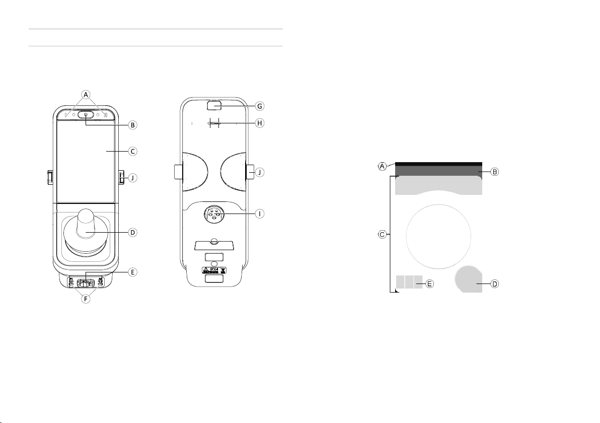
3.1UserinterfaceREM400..........................9
3.2Screencompositionoverview.....................9
3.2.1Batterybar................................10
3.2.2StatusBar.................................10
3.2.3UserFunctionCardOverview...................11
3.3Navigationbutton..............................15
3.4LabelsontheProduct...........................16
4Setup...........................................20
4.1Generalinformationonsetup.....................20
4.1.1ConditionalControlInput/Output(ControlIO).......20
4.2Wiring......................................20
4.3Connectingtheremote..........................21
5Usage..........................................23
5.1PoweringUp/DownRemote.......................23
5.2MenuScreen.................................24
5.2.1ControlsonMenuScreen......................25
5.2.2ConguringTime............................26
5.2.3LockingScreentoAvoidUnintentionalResponse.....27
5.2.4ConguringSettings..........................28
5.2.5ConguringOdometer........................30
5.3SelectingFunctions.............................31
5.3.1FunctionChangeInhibits......................31
5.4UsingDirectNavigation..........................31
5.4.1Swipe-and-TapMode.........................32
5.4.2Tap-OnlyMode.............................33
5.4.3ControlInput(CI)............................34
5.5UsingIndirectNavigation.........................34
5.5.1QuadrantMapping...........................36
5.5.2MenuSelect...............................37
5.5.3NavigationEntryPointsinMenuSelect...........40
5.5.4MenuScan................................41
5.5.5NavigationEntryPointsinMenuScan............44
5.6Usingthemultipurposebuttons....................46
5.7UsingtheToggleSwitches(Optional)................46
5.8Proportional/DiscreteDrivingMode.................47
5.8.1UsingJoystick..............................47
5.8.2ControllingMaximumSpeed....................48
5.9Latcheddrivingmode...........................50
5.9.1Externalstopswitch..........................52
5.9.21StepUp.................................53
5.9.33StepUp.................................54
5.9.45StepUp.................................55
5.9.53StepUp/Down............................56
5.9.65StepUp/Down............................57
5.9.7CruiseControl..............................58
5.10Emergencystop...............................59
5.11Operatingthepositionlights.....................59
5.12Operatingthehazardlights......................60
5.13Operatingthedirectionindicators.................62
5.14Operatingthehorn............................63
5.15OperatingLightingFunctionsandHornviaUtility
FunctionCard................................63
5.16Locking/unlockingtheremote....................64
5.17RestMode..................................65
5.18Thesleepmode..............................66
5.19Operatingpoweredseatingfunctions...............67
5.19.1ThroughSeatingCards.......................67
5.19.2ThroughExternalSwitches....................69

5.19.3SpeedReductionandSeatingFunctionInhibits.....73
5.20ConnectivityCards.............................75
5.20.1ConguringConnectivityCard..................76
5.20.2MouseMover.............................84
5.20.3SwitchControl.............................88
5.21AudibleCues.................................94
5.22Usingsecondaryinputs.........................97
5.22.1UsingManualSwing-AwayChinControl..........98
5.22.2UsingPoweredSwing-AwayChinControl.........100
5.22.3UsingtheCompactSingleSwitchJoystick.........101
5.22.4UsingMicroExtremityControlJoystick...........102
5.22.5UsingPediatricCompactJoystick...............103
5.22.6UsingtheSip-N-Puff.........................104
5.22.7UsingtheSip-N-PuffHeadArray................105
5.22.8UsingtheHeadArray........................107
5.22.9UsingtheFourSwitchProximityArray...........110
5.22.10UsingtheRemoteStopSwitch................111
5.22.11UsingtheWirelessMouseEmulator............111
5.23DisablingBluetooth............................114
5.24ChargingtheBatteries..........................114
5.24.1Batteryalarms.............................115
5.25UsingtheUSBcharger..........................115
6Maintenance.....................................117
6.1ReplacingMouthpiece...........................117
6.2ReplacingSalivaTrap............................117
6.3CleaningSip-N-Puff.............................118
7Troubleshooting...................................119
7.1Faultdiagnosis................................119
7.1.1FaultCodesandDiagnosisCodes................119
7.2OON(“OutOfNeutral”).........................121
8TechnicalData....................................123
8.1Technicalspecications..........................123

General
1General
1.1AboutThisManual
Thisdocumentisasupplementtothepowerwheelchair’s
documentation.
TheproductitselfdoesnotbearaCEmarkbutispartofa
productthatcomplieswiththeMedicalDeviceRegulation
2017/745,ClassIconcerningmedicaldevices.Itistherefore
coveredbythepowerwheelchair’sCEmarking.Seethe
powerwheelchair’sdocumentationformoreinformation.
Notethattheremaybesectionsinthisdocument,whichare
notrelevanttoyourproduct,sincethisdocumentapplies
toallavailablemodels(onthedateofprinting).Ifnot
otherwisestated,eachsectioninthisdocumentreferstoall
modelsoftheproduct.
Invacarereservestherighttoalterproductspecications
withoutfurthernotice.
Beforereadingthisdocument,makesureyouhavethe
latestversion.YoundthelatestversionasaPDFonthe
Invacarewebsite.
Formoreinformationabouttheproduct,forexample
productsafetynoticesandproductrecalls,contactyour
Invacarerepresentative.Seeaddressesattheendofthis
document.
1.2SymbolsinThisManual
Symbolsandsignalwordsareusedinthismanualandapply
tohazardsorunsafepracticeswhichcouldresultinpersonal
injuryorpropertydamage.Seetheinformationbelowfor
denitionsofthesignalwords.
WARNING
Indicatesahazardoussituationthatcouldresult
inseriousinjuryordeathifitisnotavoided.
CAUTION
Indicatesahazardoussituationthatcouldresult
inminororslightinjuryifitisnotavoided.
IMPORTANT
Indicatesahazardoussituationthatcouldresult
indamagetopropertyifitisnotavoided.
Tips
Givesusefultips,recommendationsand
informationforefcient,trouble-freeuse.
Tools
Identiesrequiredtools,componentsanditems
whichareneededtocarryoutcertainwork.
1.3WarrantyInformation
Weprovideamanufacturer’swarrantyfortheproduct
inaccordancewithourGeneralTermsandConditionsof
Businessintherespectivecountries.
Warrantyclaimscanonlybemadethroughtheprovider
fromwhomtheproductwasobtained.
1.4ServiceLife
Weestimateaservicelifeofveyearsforthisproduct,
provideditisusedinstrictaccordancewiththeintended
useassetoutinthisdocumentandallmaintenanceand
1637423-H5

Invacare®LiNX
servicerequirementsaremet.Theestimatedservicelifecan
beexceedediftheproductiscarefullyusedandproperly
maintained,andprovidedtechnicalandscienticadvances
donotresultintechnicallimitations.Theservicelifecan
alsobeconsiderablyreducedbyextremeorincorrectusage.
Thefactthatweestimateaservicelifeforthisproductdoes
notconstituteanadditionalwarranty.
1.5LimitationofLiability
Invacareacceptsnoliabilityfordamagearisingfrom:
•Non-compliancewiththeusermanual
•Incorrectuse
•Naturalwearandtear
•Incorrectassemblyorset-upbythepurchaserora
thirdparty
•Technicalmodications
•Unauthorisedmodicationsand/oruseofunsuitable
spareparts
61637423-H

Safety
2Safety
2.1Generalsafetynotes
WARNING!
Riskofinjuryordamagetothemobilitydevice
Donotinstall,maintainoroperatethisequipment
beforeyouhavereadandunderstoodallthe
instructionsandallthemanualsforthisproduct
andallotherproductsthatyouuseorinstall
togetherwiththisproduct.
–Followtheinstructionsintheusermanuals.
WARNING!
Riskofseriousinjuryordamagetothemobility
deviceorsurroundingproperty
Wrongsettingscanmakethemobilitydevice
uncontrollableorunstable.Anuncontrolledor
unstablemobilitydevicecancauseanunsafe
situationsuchasacrash.
–Performanceadjustmentsmustonlybemade
byqualiedtechniciansorbypersonswho
completelyunderstandtheprogramming
parameters,theadjustmentprocess,the
congurationofthemobilitydeviceandthe
capabilitiesofthedriver.
–Performanceadjustmentsmustonlybemade
indryconditions.
WARNING!
Riskofinjuryordamageduetoelectricalshorts
Connectorpinsoncablesconnectedtothepower
modulecanstillbeliveevenwhenthesystem
isoff.
–Cableswithlivepinsshouldbeconnected,
restrainedorcovered(withnon-conductive
materials)sothattheyarenotexposedto
humancontactormaterialsthatcouldcause
electricalshorts.
–Whencableswithlivepinshavetobe
disconnected,forexample,whenremovingthe
buscablefromtheremoteforsafetyreasons,
makesuretorestrainorcoverthepins(with
non-conductivematerials).
CAUTION!
Riskofinjuryfromhotsurfaces
Remotemodulecangethotwhenexposedto
strongsunlightforlongperiods.
–Donotleavemobilitydeviceindirectsunlight
forlongperiods.
Riskofdamagetotheconnectorpins
Ifyoutouchtheconnectorpins,theycanbecome
dirtyortheycanbedamagedbyelectrostatic
discharge.
–Donottouchtheconnectorpins.
1637423-H7

Invacare®LiNX
Riskofdamagetothemobilitydevice
Therearenouser-serviceablepartsinsideany
case.
–Donotopenordisassembleanycase.
Riskofinjuryduetounintendedmovement
Itisrecommendedthatthemobilitydevice,tted
withaGyromodule,hasadrivefunctionwith
disabledGyro.Ifthemobilitydeviceisusedina
movingvehicle(e.g.boat,busortrain)maybe
theGyrofunctionisimpairedanddrivedemands
canresultinunintendedmovement.
–Whendrivingonamovingvehiclechoosea
drivefunctionwithdisabledGyro.
–Ifthemobilitydevicedoesnothaveadrive
functionwithdisabledGyro,contactyour
Invacareprovider .
81637423-H

Components
3Components
3.1UserinterfaceREM400
AMultipurposebuttons
BON/OFFbutton/StatusLED
CTouchdisplay
DJoystick
EBussocket
FStereojacksockets
GInfraredtransmitter
HSpeaker
IChargersocket
JToggleswitches
3.2Screencompositionoverview
ABatterybar
BStatusbar
CUserfunctioncard
DNavigationbutton
EFunctioninformation
1637423-H9

Invacare®LiNX
3.2.1Batterybar
Thebatterybarprovidesagraphicaldisplayofthebattery’s
currentstateofchargeand,whenabatterychargeris
connected,thechargingstatus.
Batterybardisplaysgreen
whenstateofchargeis
between60and100%.
Batterybardisplaysorange
whenstateofchargeis
between20and59%.
Batterybardisplaysred
whenstateofchargeisless
than20%.
Charging.
3.2.2StatusBar
Fig.3-1
AProlename
BTime
CStatusinformation
ProleName
Theprolenamecanonlybesetbytheprovider .
Time
Thetimeisdisplayedasa12–or24–hourclock.Itisset
usingthecoordinateduniversaltime(UTC)andanoffset
basedonthelocation(country)oftheuser.TheUTCis
automaticallyacquiredwhenasystemisconnectedtoa
programminganddiagnostictool.Thecountry-basedoffset
issetthroughtheremotemodule’sMenuscreen.See5.2.4
ConguringSettings,page28.
StatusInformation
ThestatusinformationdisplaysthecurrentstateoftheLiNX
systemwithstatusicons.
Thisnotiesyouthatadrivelock-out
isactive.Adrivelock-outisastate
thatpreventsthewheelchairbeing
driven.See5.19.3SpeedReductionand
SeatingFunctionInhibits,page73for
moreinformationaboutlock-outsand
slow-downs.
Thisnotiesyouthatadriveslow-down
isactive.Adriveslow-downisastate
thatpreventsthewheelchairbeing
drivenatmaximumspeedforsafety
reasons.Instead,thewheelchairis
allowedtodriveatareducedspeed
forthedurationoftheactivedrive
slow-down.See5.19.3SpeedReduction
andSeatingFunctionInhibits,page73
formoreinformationaboutlock-outs
andslow-downs.
101637423-H

Components
Thisnotiesyouthatafaultoccurred.
Thenumberindicatesthetypeoffault.
See7.1.1FaultCodesandDiagnosis
Codes,page119formoreinformation
aboutfaultcodes.
Thisnotiesyouthataseatinglock-outis
active.Aseatinglock-outisastatethat
preventsthewheelchair’sseatingbeing
operated.See5.19.3SpeedReduction
andSeatingFunctionInhibits,page73
formoreinformationaboutlock-outs
andslow-downs.
ThisnotiesyouthatBluetooth
connectivityisdisabled.See5.23
DisablingBluetooth,page114formore
informationaboutdisablingBluetooth.
Threebatteryalarmsareshownontheright-handsideof
thestatusbar.See5.24.1Batteryalarms,page115 .
3.2.3UserFunctionCardOverview
Left-orRight-Handed
WiththeLiNXsystem,itispossible,toadjustthefunction
cardsforleft-handedorright-handedusers.See5.2Menu
Screen,page24.
Fig.3-2Left-handedFig.3-3Right-handed
Beaware,thatinthefollowingmanualright-handed
functioncardsaredisplayedonly.Allbuttonshave
thesamefunctionsforright-andleft-handed,sothe
descriptionscanbeusedforleft-handedusers,too.
FunctionCardHeader
Fig.3-4
Thefunctioncardtypeisidentiedbythecolorofthe
functioncard’sheader:
•greenindicatesadrivecard,
•orangeindicatesaseatingcard,
•blueindicatesaconnectivitycard,and
•purpleindicatesautilitycard.
TheiconAindicatesthetypeofprimaryinput.
1637423-H11

Invacare®LiNX
ThetextBisprogrammablebyyourproviderandcanbe
usedtonamethefunction.
IndicatorMeaning
DLX-REM400
DLX-REM500
DLX-REM2xx
DLX-CR400
DLX-CR400LF
DLX-ACU200
Inputmoduleor
third-partyinterface
HeadArray
SipandPuff
Userswitch
DriveCard
Fig.3-5
Drivecardscanbepre-setwithdifferentmaximumspeeds
totyourneedsandyourenvironment.Forexampleadrive
cardwithpre-setlowermaximumspeedcanbeusedfor
indoorsandadrivecardwithpre-settotalmaximumspeed
foroutdoors.Inadditiontothatyoucanalsocontrolthe
pre-setmaximumspeed,see5.8.2ControllingMaximum
Speed,page48.
Withadrivecardyouarealsoabletosoundthehornandto
operatethelightingfunctions.See5.14Operatingthehorn,
page63and5.11Operatingthepositionlights,page59.
Thespeedometer/odometerfeatureisenabledbythe
manufacturer.Ifthemanufacturerdoesnotenableit,you
donothaveaspeed/distanceindication.Ifitisenabled,you
canchoosetodisplaythespeedometer/odometerandyou
cansettheunitstometricorimperial,see5.2.4Conguring
Settings,page28.
121637423-H

Components
Speedometerdisplaysstandstill.
Whiledriving,thespeedometerdisplaysthe
wheelchair’scurrentspeed.
Theodometerdisplaysthedistancetravelled
bythewheelchairsinceitwaslastresetto
zeroorrolledovertozero.
Theodometercandisplayuptoamaximum
distanceof9999kmormiles,afterwhich
itrollsovertozero.
Atanytimetheodometercanberesetback
tozero,see5.2.5ConguringOdometer,
page30.
Thefunctioninformationdisplayseitherthelatcheddriving
mode,see5.9Latcheddrivingmode,page50ortheGyro
indication,seetablebelow.
nosymbolNoGyroisconnectedtothesystemor
enabledfordrivefunction.
Gyrodisabled.
Gyroenabled.
SeatingCard
Fig.3-6
Seatingcardsareforoperatingtheseatingfunctions,see
5.19.1ThroughSeatingCards,page67.
ConnectivityCard
Fig.3-7MouseMoverfunctionFig.3-8SwitchControlfunction
Connectivitycardsallowyoutocommunicatewithexternal
devices.Theconnectivityfunctionsthataresupportedby
1637423-H13

Invacare®LiNX
yourremoteareMouseMoverandSwitchControl.By
default,thesefunctionsaredisabled.Contactyourprovider
tochangetheconguration.
ThemousemoverallowsyoutocontrolthecursoronaPC
orlaptop’sscreenwithauserinputonthewheelchair,such
asthejoystickontheremotemoduleoranexternaljoystick.
Switchcontrolisanaccessibilityfeaturethatallowsyouto
navigateandselectitemsonyouriOSorAndroiddevice
usingtheremote'sjoystickortouchscreen.
FormoreinformationaboutConnectivitycardsandhowto
usethem,see5.20ConnectivityCards,page75.
UtilityCard
Fig.3-9Exampleofa
three-quadrant(3Q)navigation
utilitycard
Fig.3-10Exampleofa
four-quadrant(4Q)navigation
utilitycard
Utilitycardallowsyoutooperatesystemcontrols(suchas
lightingfunctionsandhorn)aswellascontroloutputswith
externalinputs.Theutilitycardfunctionissuitableforboth
three-quadrant(3Q)andfour-quadrant(4Q)inputs.
Utilitycardallowsyoutooperatetwocontrols/outputs
perquadrant,accordingtothedurationthattheuserinput
isactivated:
•AShortpress/
Momentarypress,
and
•BLongpress.
Fig.3-11
Bydefault,thisfunctionisonlyenabledforchair
congurationswithanexternalcontrolinputthatwillnot
allowthecontrolofhornorlights.Contactyourprovider
tochangethecongurationandtosetupyourdesired
operations.
Foranexamplehowtouseanutilitycardindailyuse,
see5.15OperatingLightingFunctionsandHornviaUtility
FunctionCard,page63.
141637423-H

Components
Arrangement
Functioncards
F1F2F3F4F5F6
P1
P2
P3
Pro-
les
P4
Userfunctioncardsarearrangedinrowsofproles.Each
prolecanholduserfunctioncards,whichcanbeofthe
sametype,forexamplealldrivecards,orcanbeamixture
ofdrive,seatingandconnectivitycards.
Themaximumnumberoffunctioncardsacrossallprolesis
40.Inacongurationwithveproles,forexample,each
prolecanholduptoeightfunctioncards.
3.3Navigationbutton
Dependingonthecongurationoftheremotemodule
andtheuser’sneeds,thenavigationbuttonisdisplayed
bottom-leftorbottom-rightonthescreen.
Whenactivated,thenavigationbuttonchangesitscolor
fromgreytoblue.
Thenavigationbuttonhastwoimportantfunctions:
1.Avisualindicationoftheconguredinteractionmode.
Conguredforswipe-and-tapactions
Thismeans,thatswipingandtappingthescreen
activatesdifferentfunctions.
Conguredfortapactions
Thismeans,thatonlytappingthescreenactivates
differentfunctions.Swipeinputsareignored.
Formoreinformationaboutchangingthe
interactionmode,referto5.2.4Conguring
Settings,page28.
2.Anavigationfunctiondependingoncontextand
activationduration.Forexample,ashortpresson
thenavigationbutton,whileviewinganactiveuser
functioncard,opensthecardpreviewdisplay,referto
5.3SelectingFunctions,page31.Alongpressopens
thestatusscreen,referto5.2.4ConguringSettings,
page28.
Additionaltothetouchdisplay,externalinputscanbeused
tointeractwiththesystem,referto5.22Usingsecondary
inputs,page97.
1637423-H15

Invacare®LiNX
3.4LabelsontheProduct
LabelsonDynamicControls’Parts
LabelsofDynamicControls’partsarelocatedonrearsideof
thepart.Dependingonthepartnotalllabelsareavailable.
Fig.3-12Rearsideof
DLX-REM400
Fig.3-13RearsideofDLX-IN500
inputmodule
AProductlabelcontaining:
1.Partnumber
2.DynamicControlslogo
3.DynamicControls’part
description
4.DynamicControls'
websiteaddress
5.Serialnumber
6.Warningtoread
manualbeforeuse
7.Ingressprotection
rating
8.WEEEsymbol
BHardwareandapplication
rmwareversionlabel:
1.Hardwareversion
2.Hardwaremajor
version
3.Hardwareminor
version
4.Applicationversion
5.Applicationmajor
version
6.Applicationminor
version
161637423-H

Components
CProductlabelcontaining:
•DynamicControls'logo
•Theproduct'sbarcode
•Theproduct'sserial
number
•Theproduct'spart
number
DTamperevidentseal.
EThisistheWEEEsymbol
(WasteElectricaland
ElectronicEquipment
Directive).
Thisproducthasbeen
suppliedfroman
environmentallyaware
manufacturer.Thisproduct
maycontainsubstances
thatcouldbeharmful
totheenvironmentif
disposedofinplaces
(landlls)thatarenot
appropriateaccordingto
legislation.
•The‘crossedout
wheeliebin’symbolis
placedonthisproduct
toencourageyou
torecyclewherever
possible.
•Pleasebe
environmentally
responsibleandrecycle
thisproductthrough
yourrecyclingfacility
atitsendoflife.
FIPX4Thisistheenclosure's
ingressprotectionrating.
1637423-H17

Invacare®LiNX
G
READINSTALLATION
MANUALBEFOREUSE
Recommendationtoread
theinstructionmanual
beforeusingthemodule.
HProductlabelcontaining:
•DynamicControls'
websiteaddress
•DynamicControls’
Bluetoothregistration
Serialnumberanddateofmanufacture
TheserialnumberonaDynamicControlsproductprovides
boththedateofmanufactureaswellasauniqueserial
numberfortheparticularmodule.
Theformat,asshownabove,isMYYnnnnnn,where:
•Misforthemonthofmanufacture,usingthelettersA
toL(A=Jan,B=Feb,C=Mar,etc.),
•YYistheyearofmanufacture,
•nnnnnnisauniquesixdigitsequentialnumber.
Forexample,theremote’sserialnumber,asshownabove,
beginswithA14indicatingthatitwasmanufacturedin
January2014,anditsunique,sequentialvalueis132800.
LabelsonToggleSwitches
Fig.3-14
Power
Speedpotleft
Speedpotright
Functionandprole
Seating
A
Blank
181637423-H

Components
LabelsonAdaptiveSwitchLabs’Parts
LabelsofAdaptiveSwitchLabs’partsarelocatedeitheron
leftrearsideofthepart(headarrays)ortheinterfacebox.
Dependingontheusedpartnotalllabelsareavailable.
Productlabel(headarray)
containing:
•A:AdaptiveSwitch
Labs’logo
•B:Serialnumber
Productlabel(interface
boxes)containing:
•A:Modelnumber
•B:Serialnumber
•C:AdaptiveSwitch
Labs’logo
•D:AdaptiveSwitch
Labs’contact
information
Productlabelcontaining:
•AdaptiveSwitchLabs’
Bluetoothregistration
•Informationabout
conditions
1637423-H19

Invacare®LiNX
4Setup
4.1Generalinformationonsetup
Thetasksdescribedinthischapterareintendedtobe
performedbytrainedandauthorizedservicetechnicians
forinitialsetup.Theyarenotintendedtobeperformed
bytheuser.
4.1.1ConditionalControlInput/Output(ControlIO)
Theindividualprogrammingofthewheelchairwithone
oftheLiNXAccessToolsmustbemadebyaqualied
technician.
TheLiNXsystemnowsupportsconditionalcontrolIO,
extendingthecurrentalwaysrule-basedmodel,wherea
singleoutputactionisalwaysactivatedinresponsetoa
singleinputaction.Withtheintroductionofconditional
controlIO,aqualiedtechniciancannowcreate:
•multiplealwaysrules—oneormoreoutputsare
alwaysactivatedfromasingleinput,
•conditionalrules—oneormoreoutputsareactivated
fromasingleinputifthespeciedconditionsaretrue,
•conditional/elserules—anoutputisactivatedfrom
asingleinputifaspeciedconditionistrue,else
(otherwise)analternativeoutputisactivatedifthe
samespeciedconditionisfalse.
ThebenetofconditionalIOistwo-fold.Firstly,asingle
inputcannowactivatemultipleoutputs.Secondly,control
inputscanbeoverloaded.Overloadingiswhereasingle
inputcanhavemultipleuses,eachofwhichdependson
speciedconditions.Thismeansthataninputcanbeused
toactivateoneoutputifthesystemisinonestateor
function,andthenactivateadifferentoutputwhenthe
systemisinanotherstateorfunction.Forexample,abuddy
buttonthatisusedtostopawheelchairwhendrivingcan
alsobeusedtoextendaseatingmotionwheninaseating
function.
4.2Wiring
Forsafeandreliableoperation,theinstallationofloomsand
cablesmustfollowthebasicprinciplesofpowerwiring.
Cablesmustbesecuredbetweentheirconnectorsandany
pointofexingsothatexingforcesarenottransferred
totheconnectors.
CAUTION!
Riskofinjuryanddamagetotheremote
Damagetocablesincreaseswiringimpedance.A
damagedcablecanpotentiallyproducelocalized
heat,sparksorarcingandbecomeasourceof
ignitiontosurroundingammablematerial.
–Theinstallationmustensurethatallpower
cables,includingthebuscable,areprotected
againstdamageandpotentialcontactwith
ammablematerials.
Riskofdamage
Cablesandremotemodulescangetdamagedif
notpositionedproperly.
–Routeandpositioncablesandremotemodules
sothattheyarefreefromphysicalstrain,abuse
ordamage,suchassnagging,crushing,impacts
fromexternalobjects,pinchingorabrasion.
201637423-H
Other manuals for LiNX DLX-REM400
1
Table of contents
Other Invacare Remote Control manuals

Invacare
Invacare LiNX DLX-REM500 User manual

Invacare
Invacare LiNX DLX-REM110 User manual

Invacare
Invacare LiNX REM400 Configuration guide

Invacare
Invacare REM 24 SD User manual

Invacare
Invacare IDC User manual

Invacare
Invacare LiNX DLX-REM110 User manual

Invacare
Invacare MK6i Series User manual

Invacare
Invacare Shark II/SPJ+ User manual

Invacare
Invacare A-Series User manual

Invacare
Invacare G91S User manual