Inventum Technologies BV –VMS-47C55-EN-V1
5. Installation
5.1 Preparation
Disconnect power at supply line, circuit breaker or fuse
before installing the device.
Do not place the device in a metal casing.
1. Press the clip and pull the top section from the
bottom section.
2. Open the safety cover. Use a small flat-tip
screwdriver to loosen the clip.
3. When using screws: Use the mounting plate as
a template.
4. When using tape:
a. Make sure the surface is smooth,
clean, and degreased.
b. Remove the foil from the double-sided
tape.
5. Remove the breakout plastic from the cable
input of the housing.
5.2 Installation procedure
Make sure that the power supply is disabled.
Recommended position: We advise to place the sensor at
1 to 1.5 m from the ground in a living room.
1. Lead the power cable through the back hole
(A) or cable entrances (B).
2. Place the bottom section of the device.
3. Fasten the bottom section using the screws
or tape.
4. Connect the power cable in the screw
terminals.
5. Connect the 0-10Vdc output cable in the
screw terminals (OUT & GND).
5.3 Commissioning
1. Enable the 230V power supply. All LEDs are ON for 3 seconds.
2. Wait until the status LED shows the binding mode. If the device
shows another indication, the device is already bound. See 7.2
on how to bind the device again.
3. Make sure the fan box is in binding mode.
4. Tap the button. The device tries to bind to the control device. The
status LED indicates whether this has been successful. If the
connection failed, make sure that the RF Receiver is in
connection mode and try again.
6. Operation
6.1 Show status
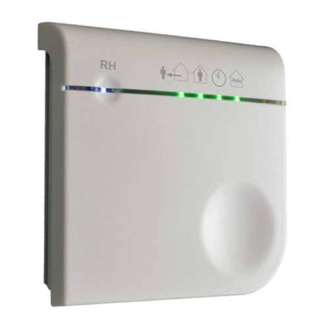
Tap the button. The Status LED and Mode LEDs show the status of
the system.
6.2 Set mode
From status screen (see 6.1)
1. Tap the button. The mode LEDs show the next selection.
2. If needed, tap the button within 2 seconds, until the selection
shows the required mode.
3. Wait 2 seconds. The device applies the requested mode. The
Status LED and Mode LEDs show the status of the system.
7. Configuration
7.1 Configuration setpoints
From the status screen (see 6.1), use table above.
1. Tap the button. The mode LEDs show the next selection.
2. If needed, tap the button within 2 seconds, until the selection
shows the item.
3. Press and hold the button until the Status LED starts flashing
white.
4. Release the button. The status LED shows the item selected, and
the Mode LEDs show its current value.
5. If needed, tap the button within 10 seconds, until the Mode LEDs
show the value to set.
When setting the fan speed, make sure that the medium fan
speed is between the low and high fan speed.
6. Wait 10 seconds. The device applies the configured value. The
Status LED and Mode LEDs show the status of the system.
7.2 Bind the device again
From the status screen (see 6.1).
1. Tap the button. The mode LEDs show the next selection.
2. If needed, tap the button within 2 seconds, until the selection
shows the 5th LED.
3. Press and hold the button until the Status LED starts flashing
white.
4. Release the button. The status LED shows the binding mode.
5. Tap the button. The device will try to bind to the control device. It
shows the result on the status LED.
7.3 Perform a factory reset
From the status screen (see 6.1).
1. See 7.2 step 1 –4.
2. Press and hold the button for 10 seconds. The status LED shows
white.
3. Release the button. The device releases its binding, resets the
configured CO2 level to the default value, and restarts. The
device will return to the binding mode.
8. Technical data
