Mark 7 BulletSense RL 1050 User manual

BULLETSENSE 1050/RL1100 INSTRUCTION MANUAL VERSION 1.2
1
101-1082: Mark 7® BulletSense
1050 Super/RL 1050/RL1100
Instruction Manual V 1.2
Read this manual completely. Understand all safety and operating instructions. Failure to
comply with the warnings and instructions may result in serious injury, illness or death.

BULLETSENSE 1050/RL1100 INSTRUCTION MANUAL VERSION 1.2
2
Package Contents
Please review these contents and inform us right away if you appear to be missing any of these items:
Item No.
Description
QTY
1
Primer Tube Assembly
1
2
BulletSense Mirror Mount Assembly
1
3
BulletSense Sensor Head Assembly
1
4
3/8” – 16 x 3 ¼” L Cap Screw
1
5
Spacer Rod
1
6
Shoulder Screw –5/16”-18
1
1
2
4
3
5
6

BULLETSENSE 1050/RL1100 INSTRUCTION MANUAL VERSION 1.2
3
Sensor Head Mounting:
1. First remove the bin support 3/8” pan head socket cap screw using a 7/32” Allen key
Figure 1: Removing Bin Support Screw.
2. Mount the BulletSense® Main Assembly on the case feeder support pole using the supplied 3/8”
socket cap screw and the aluminum spacer. Reference Figure 2 below.
Figure 2: Mounting the Main Assembly
Remove

BULLETSENSE 1050/RL1100 INSTRUCTION MANUAL VERSION 1.2
4
Mounting Configurations:
1. Before going any further, it is important to decide which station to configure BulletSense®.
BulletSense® comes configured to sense bullets in Station 8 from the factory, but it can be
configured for either station #7 or station #8. If you are running a Dillon powder check or a
Mark 7 Digital Powder Check, you must configure the mount for station #8. If you are not
running a powder check configure the mount to work with station #7.
2. To switch the mounting configuration, loosen the 2X brass thumb screws in the lower mount
and remove the upper mount. Loosen the shaft locking collar and re-clamp on the rod with a
slight gap from the upper mount as shown below.
Figure 3: Removing the upper mount for station configuration change

BULLETSENSE 1050/RL1100 INSTRUCTION MANUAL VERSION 1.2
5
3. Remove the 2X 5/16” threaded dowel pins from the upper mount. Use a ¼” wrench to remove
the pins from the lower mount and thread them into the desired mounting configuration shown
in the figure below.
Figure 4: Station 7 Setup (Left) & Station 8 Setup (Right)

BULLETSENSE 1050/RL1100 INSTRUCTION MANUAL VERSION 1.2
6
Station 8 Setup and laser Alignment (For use with Powder check):
NOTE: On RL 1050, and some very early model Super 1050, the mirror bracket can not be mounted
on the rocker bolt due to a raised ledge in the casting. For these units only the primer stack tube
can be used. Please refer to Station 7 Setup.
1. Refer to the Mounting Configurations section on Page 4 to make sure the sensor assembly is
configured properly to sense in Station 8. In the Station 8 configuration, the mirror is mounted
off a remote mount to the right of Station 3. This is how the product is factory configured.
2. Hold the primer rocking assembly in place with your finger or a pry bar and remove the shoulder
bolt, see Figure 5. Place the split washer on the longer shoulder bolt supplied with the Station 8
hardware and fasten the mount to the frame, see Figure 6.
Figure 5: Remove the shoulder bolt to mount on station 8 adapter.
Remove
Hold
Hold

BULLETSENSE 1050/RL1100 INSTRUCTION MANUAL VERSION 1.2
7
Figure 6: Mounting station 8 adapter to the RL1100 frame.
3. Slide the mirror onto the rod in the orientation shown in Figure 6. Gently tighten the set screw
to hold the assembly in place until the next step. The mirror needs to be aligned with the diode
so keep the mount snug but not fully tight at this stage.
WARNING –Class 3R laser: avoid eye contact at all times; do not look directly into the laser when
adjusting the laser alignment.
4. Power on the console which will automatically turn on the laser. Next step is to align the laser
so the mirror reflects the laser beam into the sensor. When you first power on the sensor, look
at the mirror to see where the laser beam is directed. Use a white card to help find the exact
position if it’s difficult to detect the position.
Slide mirror
assembly
onto the rod

BULLETSENSE 1050/RL1100 INSTRUCTION MANUAL VERSION 1.2
8
5. Using the brass thumbscrew beneath the laser assembly, coarse adjust the laser housing so the
laser hits the middle of the tube with the mirror mount.
Figure 7: Station 8 Setup
6. Adjust Laser beam onto the mirror with the 2X 6-32 set screws on the top of the assembly.
Once the Laser diode is hitting the mirror surface. Rotate the mirror so the laser beam is
reflected back to the sensor main body. Once the reflected laser beam appears on the sensor
main body, continue adjusting the set screws to direct the laser beam into the sensor hole as
shown in the following figures.

BULLETSENSE 1050/RL1100 INSTRUCTION MANUAL VERSION 1.2
9
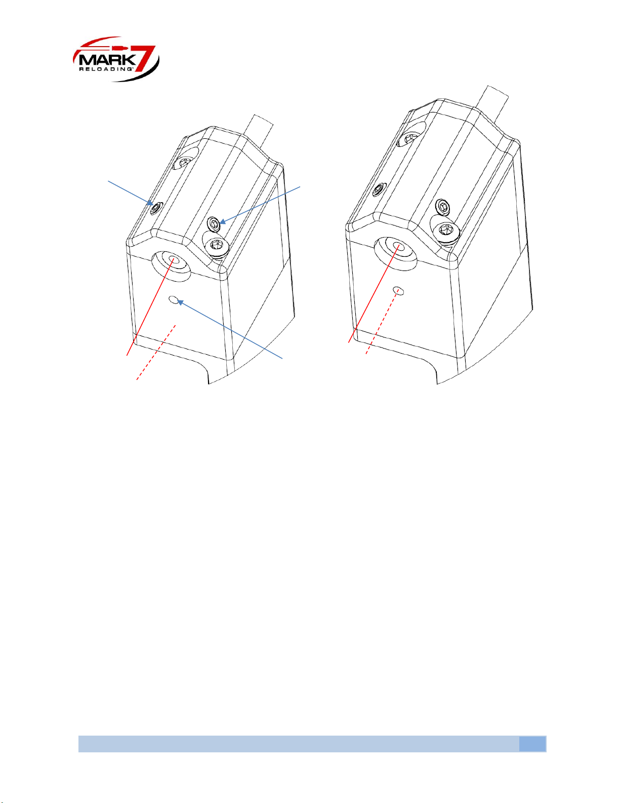
Figure 8: Laser fine adjustment. Before adjustment (left), after adjustment (right)
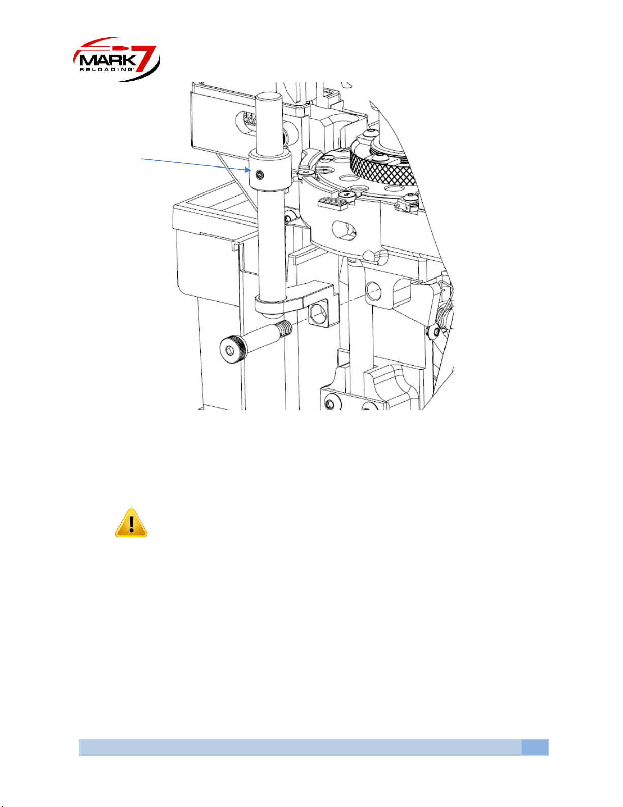
7. Now that the laser beam is aligned, lock the mirror in-place by gently tightening the set screw
on the Mirror Mount. Do not over tighten.
8. Next the Sensor vertical height must be set for the given caliber and projectile being used.
9. To set the height, place a case with the neck flared in Station 7 and place a projectile in the
proper orientation into the case at the level where it would be when dropped from the
Bulletfeeder drop tube.
10. Loosen the 2X brass thumb screws and shaft locking collar and gently position the upper mount,
shown in Figure 9, so the laser beam goes OVER the tip of the bullet and hits the mirror. The
reflected beam should return and hit the tip of the bullet, breaking the beam path, as shown in
Figure 10. When the vertical height is adjusted properly a shadow will be cast on the sensor
preventing the sensor to see the laser beam. When the bullet is not present, upside or sideways
the beam will pass over the bullet and contact the sensor triggering the machine to stop.
Adjust
Adjust
Sensor Hole

BULLETSENSE 1050/RL1100 INSTRUCTION MANUAL VERSION 1.2
10
Figure 9: Direct beam over the tip of the bullet (left) the reflected beam will hit the back side of the bullet (Right)
Figure 10: Properly orientated Bullet- Beam interrupted (Left) Improper orientated Bullet –Beam not interrupted (Right)
11. Once the proper height has been achieved ensure the 2X brass set screws are tightened and
tighten the shaft locking collar, see Figure 9. The shaft locking collar is used to lock in the
required height adjustment. If you need to remove the BulletSense® assembly for press
maintenance or for any reason you can choose to remove the upper mount only. When re-
installing, the vertical position will be maintained.
Brass Thumb Screws
Shaft Locking Collar

BULLETSENSE 1050/RL1100 INSTRUCTION MANUAL VERSION 1.2
11
Station 7 Setup and laser Alignment:
1. Refer to the Mounting Configurations section on Page 4 to make sure the sensor assembly is
configured properly to sense in station 7. In this configuration the Mirror is installed on the
primer tube.
2. Connect BulletSense® to I/O Port #3. Do not power on the console at this point.
Figure 11. Console port location
3. Remove the Dillon low primer sensor/ PrimerSense® assembly and the knurled primer tube top
nut. Then remove the priming mechanism and slide it off the primer tube. Sometimes a flat
screwdriver is needed to open the clamp for easier removal.
Figure 12: Removing low primer sensor and priming mechanism from priming tube
Remove outer tube
Remove
Remove

BULLETSENSE 1050/RL1100 INSTRUCTION MANUAL VERSION 1.2
12
4. Slide the Mirror down the tube in the orientation shown below. Gently tighten the set screw to
hold the assembly in place until the next step. The mirror needs to be aligned with the laser so
keep the mount snug but not fully tight at this stage.
Figure 13: Mounting the mirror for Station 7
WARNING –Class 3R laser: avoid eye contact at all times; do not look directly into the laser when
adjusting the laser alignment.
5. Power on the console which will automatically turn on the laser. Next step is to align the laser
so the mirror reflects the laser beam into the sensor. When you first power on the sensor, look
at the mirror to see where the laser beam is directed. Use a white card to help find the exact
position if it’s difficult to detect the position.
Tighten

BULLETSENSE 1050/RL1100 INSTRUCTION MANUAL VERSION 1.2
13
6. Using the brass thumbscrew beneath the laser assembly, coarse adjust the laser housing so the
laser hits the middle of the tube with the mirror mount.
Figure 14: Laser Beam (Not aligned) directed on the edge of the mirror.
7. Adjust Laser beam onto the mirror with the 2X 6-32 set screws on the top of the assembly.
Once the Laser diode is hitting the mirror surface. Rotate the mirror so the laser beam is
reflected back to the sensor main body. Once the reflected laser beam appears on the sensor
main body, continue adjusting the set screws to direct the laser beam into the sensor hole as
shown in the following figures.

BULLETSENSE 1050/RL1100 INSTRUCTION MANUAL VERSION 1.2
14
Figure 15: Laser fine adjustment. Before adjustment (left), after adjustment (right)
8. Now that the laser beam is aligned, lock the mirror in-place by gently tightening the set screw
on the Mirror Mount. Do not over tighten.
9. Next the Sensor vertical height must be set for the given caliber and projectile being used.
10. To set the height, place a case with the neck flared in Station 7 and place a projectile in the
proper orientation into the case at the level where it would be when dropped from the
Bulletfeeder drop tube.
11. Loosen the 2X brass thumb screws and shaft locking collar and gently position the upper mount,
shown in Figure 16, so the laser beam goes OVER the tip of the bullet and hits the mirror. The
reflected beam should return and hit the tip of the bullet, breaking the beam path, as shown in
Figure 17. When the vertical height is adjusted properly a shadow will be cast on the sensor
preventing the sensor to see the laser beam. When the bullet is not present, upside or sideways
the beam will pass over the bullet and contact the sensor triggering the machine to stop.
Adjust
Adjust
Sensor Hole

BULLETSENSE 1050/RL1100 INSTRUCTION MANUAL VERSION 1.2
15
Figure 16: Direct beam over the tip of the bullet (left) the reflected beam will hit the back side of the bullet (Right)
Figure 17: Properly orientated Bullet- Beam interrupted (Left) Improper orientated Bullet –Beam not interrupted (Right)
12. Once the proper height has been achieved ensure the 2X brass set screws are tightened and
tighten the shaft locking collar, see Figure 16. The shaft locking collar is used to lock in the
required height adjustment. If you need to remove the BulletSense® assembly for press
maintenance or for any reason you can choose to remove the upper mount only. When re-
installing, the vertical position will be maintained.
Brass Thumb Screws
Shaft Locking Collar

BULLETSENSE 1050/RL1100 INSTRUCTION MANUAL VERSION 1.2
16
Operating BulletSense®:
1. With a clear shell plate enter the Reloader application, confirm that you have the required
software firmware version.
2. BulletSense® Plugged into I/O Port 3.
3. Confirm that the laser is aligned with the sensor opening. Note: Every time the unit is turned on
the laser must be aligned to the sensor hole for the calibration process, or the sensor will not be
recognized.
4. Perform a system calibration the go to the sensors tab and make sure BulletSense® is enabled.
5. Press RUN or Single Cycle. With a clear shell plate, the following notification should appear
stating that a “Bullet Not Properly Positioned.”
Figure 18: Sensor Page (enable BulletSense®)
Figure 19: BulletSense® Notification

BULLETSENSE 1050/RL1100 INSTRUCTION MANUAL VERSION 1.2
17
Troubleshooting
Refer to the knowledge base section on our website under SUPPORT for troubleshooting articles relating
to setup and operation.
http://www.markvii-loading.com/knowledgebase
Please contact us for technical support
Phone: 1-888-462-7577
Hours: 9:00am-4:30pm, ET, M–F
This manual suits for next models
2
Table of contents
Other Mark 7 Accessories manuals