SERVICE MANUAL ODE-3 FRAME SIZE 3
Page 2of 23
Contents Page no:
Service Request Form ..........................................................................................................3
Multimeter checks:................................................................................................................3
Control terminal checks:..................................................................................................................3
Input Terminal Checks: ...................................................................................................................4
Output Terminal checks:.................................................................................................................5
IGBT tests (480V).................................................................................................................6
IGBT tests (240V).................................................................................................................7
Brake chopper test 240V & 480V..................................................................................................8
Main components on an ODE-3............................................................................................9
Control PCB......................................................................................................................................9
Power board PCB 240 & 480V.....................................................................................................10
Inrush circuit test (480V & 240V).........................................................................................12
IGBT pin outs......................................................................................................................13
4.0kW, 240V, 5.5 -7.5kW, 480V...................................................................................................13
5.5kW, 220V, 11.0kW, 480V ........................................................................................................13
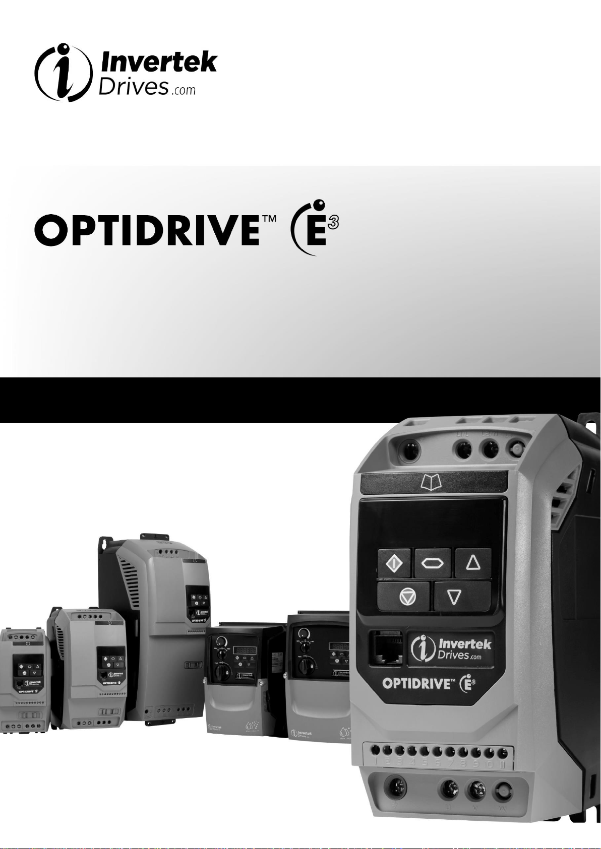
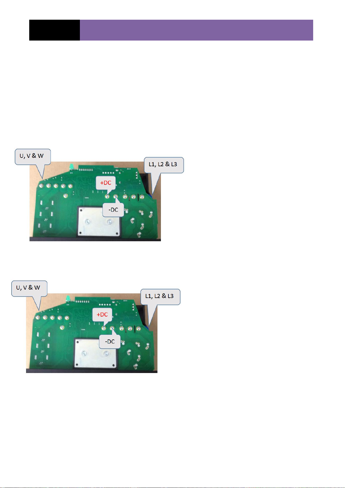
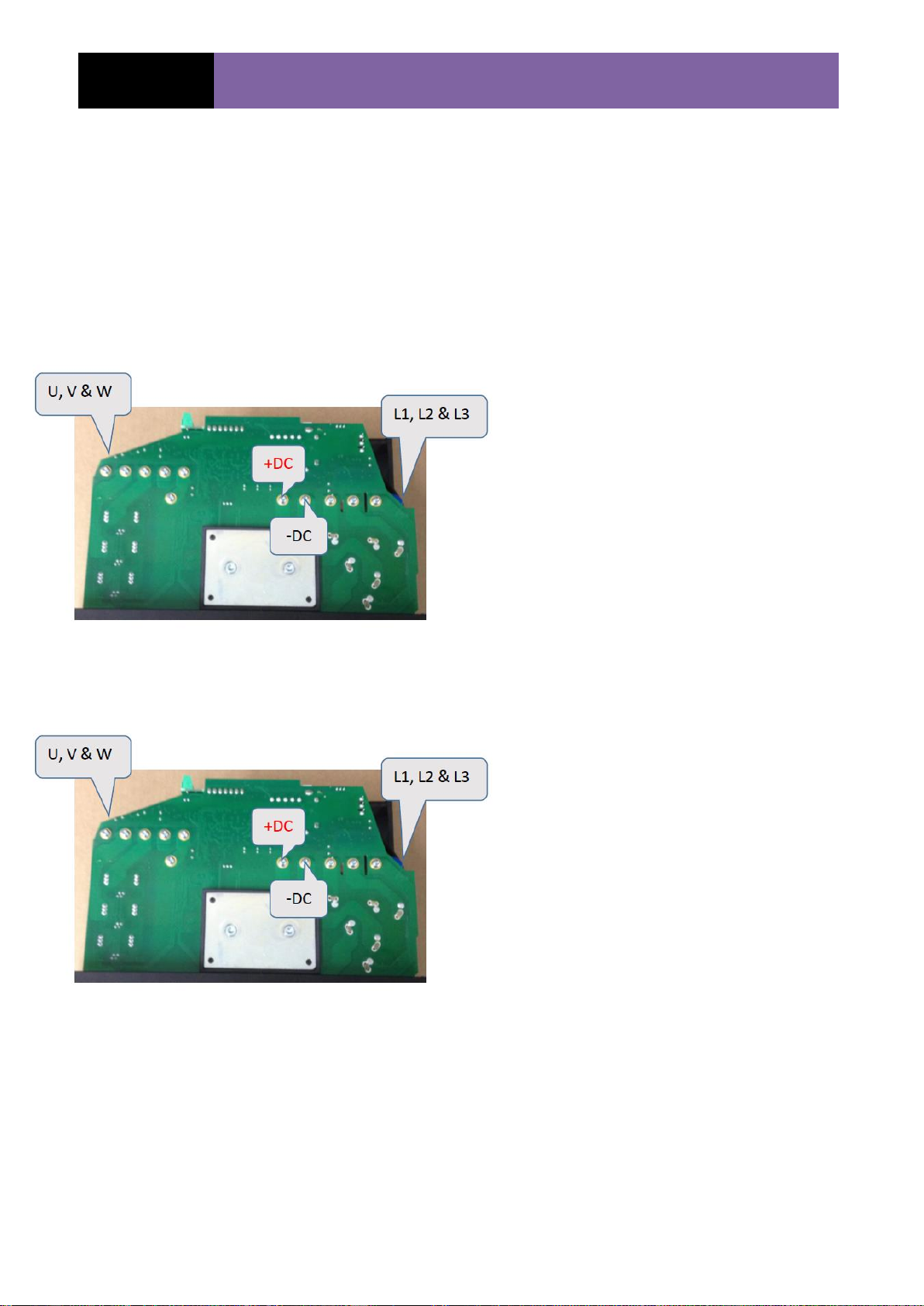
DC Bus check.....................................................................................................................14
Power board (supply rails)...................................................................................................15
Power board Pin outs..........................................................................................................16
PCB pin outs...................................................................................................................................16
Control board PCB pin outs..........................................................................................................17
Control board (Supply rails).................................................................................................18
Control board (Digital inputs/outputs, Comms & display).....................................................19
Parameter group 0..............................................................................................................20
Fault codes.........................................................................................................................21
Drive test procedure (240 - 480V).......................................................................................22