Inverto Unifiber 6286 User manual

1
User manual
Unifiber™
1310nm Optical LNB with 10.40\10.41GHz LO
IDLF-OPL410-1314X-OPR
Item:6286, 6295

2
Product description
Wideband 40 mm low noise down converter units 6286, 6295 are dedicated for operation with
the Inverto Uniber optical receivers in satellite-only installations that do not require distribution
of DTT signal.
Safety instructions
■Installation of the products must be done according IEC60728-11 and national safety standards.
■The products are powered from 10 - 20 V DC. This voltage is not dangerous to life.
■Any repairs must be done by a skilled personnel.
■Power supply must have a short circuit protection.
This product complies with the relevant clauses of the European Directive 2002/96/EC.
The unit must be recycled or discarded according to applicable local and national regulations.
This product is in accordance to following norms of EU: EMC norm EN50083-2, safety
norm EN62368-1 and RoHS norm EN50581.
This product is in accordance with Custom Union Technical Regulations:
“Electromagnetic compatibility of technical equipment“ CU TR 020/2011, “On safety of
low-voltage equipment“ CU TR 004/2011.
This product is in accordance with the UK Radio Equipment Regulations 2017, Electrical
Equipment (Safety) Regulations 2016 & Electromagnetic Compatibility Regulations 2016.
Designated standards: EN303372-2, EN55032, EN55035, EN 62368. The full text of the
UKCA declaration of conformity is available at: www.inverto.tv/support_dc
This product is in accordance with safety standard AS/NZS 60065: 2012 and EMC standards
of Australia.
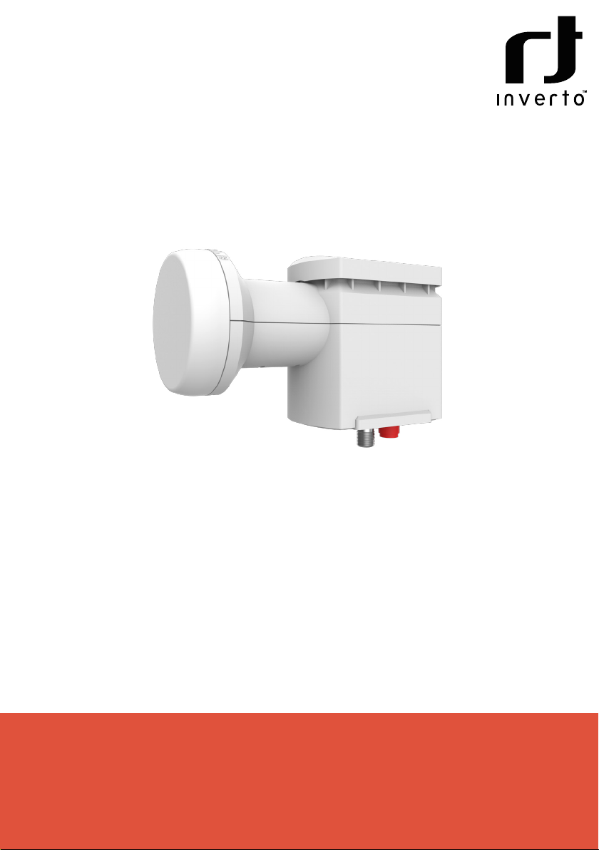
External view of 6286 / 6295
Date:27/07/2022
DO NOT SCALE DRAWING
SCALE:1:2
SHEET 1 OF 1
6268 DR-IDLF-OPL410-1314O-OPR
© 2022 FTA Communication Technologies S.à r.l.
TITLE:
REVISION
A4
FTA Communication Technologies S.à r.l., 17 Route
de Luxembourg, Gonderange, L-6182, Luxembourg
63
140
40
33
13
95
Optical
output
DC In
/Horizontal out
Figure 1. External view of the LNB

3
Optical connections
Note: All optical connectors and adapters should be cleaned before connecting them. If optical
reception power of the receiver decrease, ber connection should be cleaned and maintained. Reel
cleaners or prepackaged lint free wipes or swabs with alcohol are the most convenient means of
cleaning optical connectors. Fiber connectors should never be left uncovered.
1. Align the FC/UPC connector key-way (type R) with the acceptable key-way.
connector key-way
2. Push rmly to locate the key-ways and then rotate the coupling ring.
coupling ring
rotate clock-wise to finish
3. Guard the minimum recommended bending radius of ber cables which is 30 mm.
Installation instructions
- Read the safety instruction rst.
- For outdoor installation.
- For LNB and dish adjustment use RF test output at DC IN connector (Figure 1).
- Dish alignment can be carried out using the Horizontal polarization SAT IF signal (wideband).
The signal is AGC controlled so dish alignment should be based on maximum MER level measuring.
Optical cable installation instruction
We recommend to use relatively bigger dishes for ensure better MER value of the transmitted
signals.
2. Insert the optical cable [1] in to the appropriate hole of the
connectors cover.
3. Install the optical cable connector on the LNB adapter.
4. Remove protective lm from insulation tape.
5. Roll the insulation tape on the optical connector (the side of
the tape is not important).
6. Push connectors cover back on the LNB.
1. Take o the connectors cover by pressing its sides and pulling
downward.

4
Requirements for external power supply unit (PSU)
■Output voltage +20 V ± 1 V
■Output current Recommended to use PSU with 50%
extra power reserve
■Ripple at single and/or double < 10 mV p-p
mains frequency
■Ripple & noise < 200 mV p-p
■Double insulated (marked )
■Meet EN 55022 class B conducted emissions requirements, measuring with grounded load
* Reducer 5.5/2.1 to 3.5/1.3 mm is supplied with the product.
TECHNICAL SPECIFICATIONS
Type 6286 IDLF-OPL410-1314O-OPR 6295 IDLF-OPL410-13141-OPR
Input frequency range 10.7-12.75 GHz
Noise gure typical 0.7dB
Wideband and DTT outputs 10.40 GHz 10.41 GHz
LO initial accuracy ± 500 kHz
LO temperature drift ± 150 kHz
LO phase noise < -75 dBc/Hz@10 kHz
Cross-pole isolation 22 dB
Optical output +4 dBm, 1310 nm, FC/UPC
Main characteristics
Supply voltage 10-20 V
Power consumption 4 W max.
Operating temperature range -30° ~ +60° C
Dimensions/Weight (packed) 141x89x63 mm/0.35 kg

5

6
For purpose of brevity, some product descriptions in this sheet remain at platform level and may not be referred to as de-
tailed datasheets of the products. Inverto Digital Labs reserves the right to amend, omit or add products, product-lines, and /
or features without notice. As product specifications may change without notice, always contact Inverto to obtain the latest
product specification sheets.
FTA Communication Technologies S.à.r.l Tel. +352 264 367 1 Fax. +352 264 313 68 V050122
This manual suits for next models
1
Table of contents
Other Inverto Media Converter manuals