Invest Solar SIC-P-M-3T24-IS User manual


Table Of Contents
Information on this Manual.................................................................................................................................................................. 1
Validity...............................................................................................................................................................................................1
Scope................................................................................................................................................................................................. 1
Target Group.................................................................................................................................................................................... 1
Safety Instructions.......................................................................................................................................................................... 1
Introduction.............................................................................................................................................................................................2
Product Overview
.............................................................................................................................................................................3
Installation...............................................................................................................................................................................................4
Unpacking and Inspection..............................................................................................................................................................4
Mounting the Unit............................................................................................................................................................................4
Battery Connection.......................................................................................................................................................................... 5
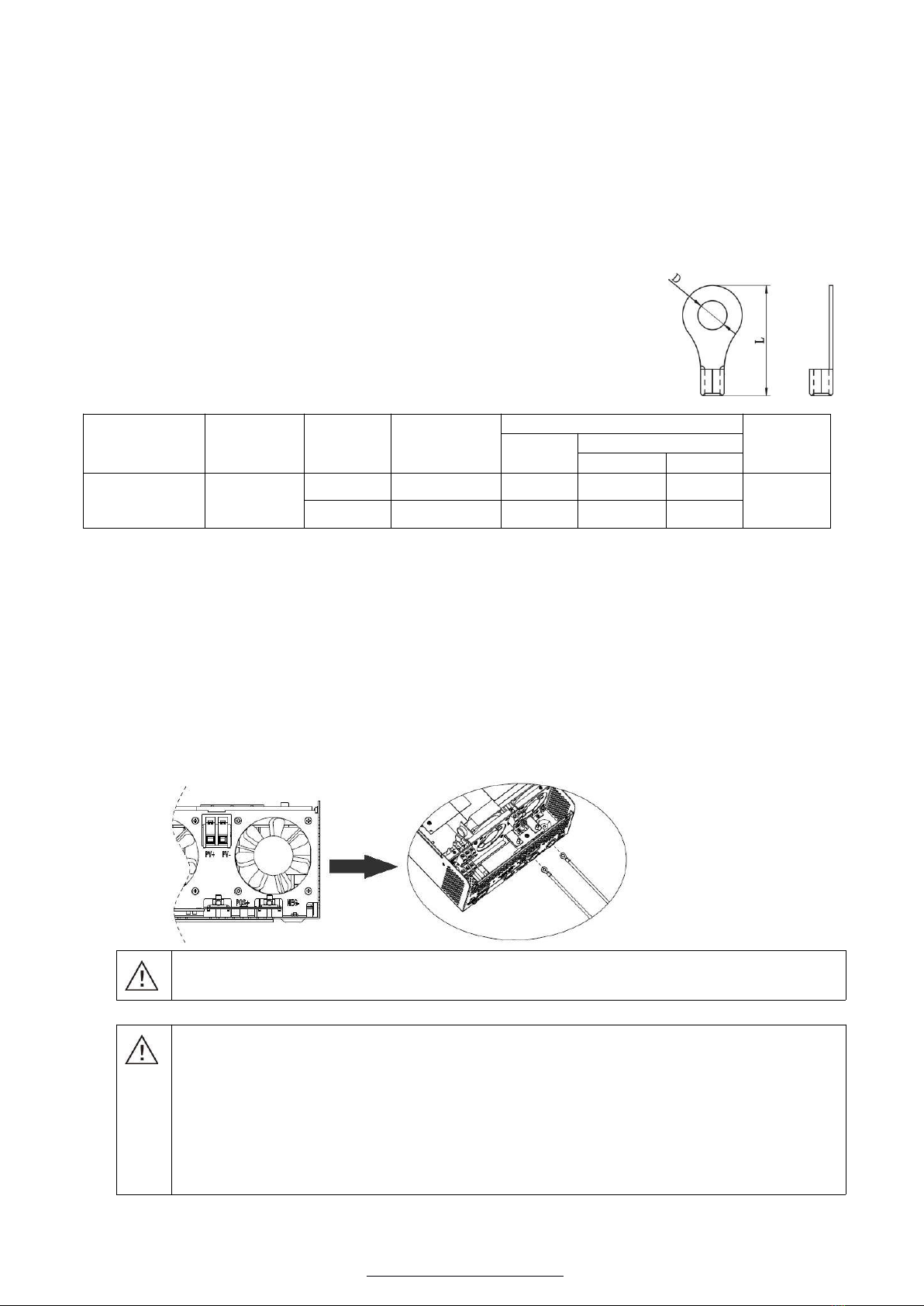
Lead-acid Battery Connection....................................................................................................................................................5
Lithium Battery Connection (optional)..................................................................................................................................... 6
AC Input/Output Connection......................................................................................................................................................... 8
PV Connection.................................................................................................................................................................................. 9
Communication Connection......................................................................................................................................................... 10
Dry Contact Signal.........................................................................................................................................................................10
Operation...............................................................................................................................................................................................11
Power ON/OFF............................................................................................................................................................................... 11
Operation and Display Panel........................................................................................................................................................11
LCD Display Icons..................................................................................................................................................................... 12
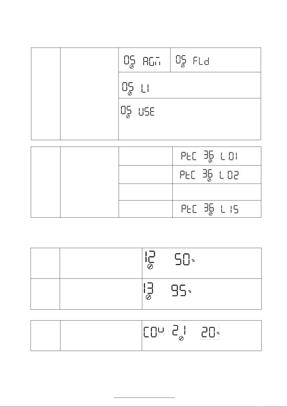
LCD Setting................................................................................................................................................................................ 14
Display Setting............................................................................................................................................................................... 18
Operating Mode Description........................................................................................................................................................ 21
Warning Indicator..........................................................................................................................................................................22
Fault Reference Code....................................................................................................................................................................23
Specifications........................................................................................................................................................................................ 24
Trouble Shooting.................................................................................................................................................................................. 28

http://www.investsolar.co.za
1
Information on this Manual
Validity
This manual is valid for the following devices:
Off grid solar inverter with MPPT controller, 3KVA, model SIC-P-M-3T24-IS
Scope
This manual describes the assembly, installation, operation and troubleshooting of this unit. Please read this
manual carefully before installations and operations.
Target Group
This document is intended for qualified persons and end users. Tasks that do not require any particular
qualification can also be performed by end users. Qualified persons must have the following skills:
Knowledge of how an inverter works and is operated
Training in how to deal with the dangers and risks associated with installing and using electrical devices
and installations
Training in the installation and commissioning of electrical devices and installations
Knowledge of the applicable standards and directives
Knowledge of and compliance with this document and all safety information
Safety Instructions
WARNING: This chapter contains important safety and operating instructions.
Read and keep this manual for future reference.
1.
CAUTION – Only qualified personnel can install this device with battery.
2.
Before using the unit, read all instructions and caution marks on the unit, understand the batteries and all
appropriate sections of this manual.
3.
NEVER cause AC output and DC input short circuited. Do NOT connect to the mains when DC input short
circuits.
4.
NEVER charge a frozen battery.
5.
Do not disassemble the unit. Take it to a qualified service center when service or repair is required.
Incorrect re-assembly may result in a risk of electric shock or fire.
6.
To reduce risk of electric shock, disconnect all wiring before attempting any maintenance or cleaning.
Turning off the unit will not reduce this risk.
7.
Be very cautious when working with metal tools on or around batteries. A potential risk, such as dropping a
tool to spark or short circuit batteries or other electrical parts, could cause an explosion.
8.
For optimum operation of this off grid solar inverter, please follow required spec to select appropriate cable
size. It’s very important to correctly operate this off grid solar inverter.
9.
Please strictly follow installation procedure when you want to disconnect AC or DC terminals. Please refer
to INSTALLATION section of this manual for the details.
10.
GROUNDING INSTRUCTIONS –This off grid solar inverter should be connected to a permanent grounded
wiring system. Be sure to comply with local requirements and regulation to install this inverter.
11.
Fuses with particular standard are provided as over-current protection for the battery supply.
12.
Warning!! Only qualified service persons are able to service this device. If errors still persist after following
troubleshooting table, please send this off grid solar inverter back to local dealer or service center for
maintenance.

http://www.investsolar.co.za
2
Introduction
Hybrid Power System
This is a multifunctional off grid solar inverter, integrated with a MPPT solar charge controller, a high frequency
pure sine wave inverter and a UPS function module in one machine, which is perfect for off grid backup power
and self-consumption applications. The transformerless design provides reliable power conversion in compact
size.
The whole system also need other devices to achieve complete running such as PV modules, generator, or
utility grid. Please consult with your system integrator for other possible system architectures depending on
your requirements. The WiFi / GPRS module is a plug-and-play monitoring device to be installed on the
inverter. With this device, users can monitor the status of the PV system from the mobile phone or from the
website anytime anywhere.
Features
power 3KW, power factor 1
MPPT solar charge controller
High frequency inverter with small size and light weight
Pure sine wave AC output
Overload, short circuit and deep discharge protection
Configurable AC/ solar input priority via LCD setting
Compatible to mains voltage or generator power
WIFI/ GPRS remote monitoring

http://www.investsolar.co.za
3
Product Overview
Lead-acid Model Lithium Model
6. AC input
7. WiFi/GPRS communication port
8. USB communication port
9. Dry contact
10. PV input
11. Power on/off switch
12. Battery input
15. AC output
16. Circuit breaker
17. BMS communication Port (only supported the RS485 protocol)
18. RS485 communication Port (for expansion)
1. LCD display
2. Status indicator
3. Charging indicator
4. Fault indicator
5. Function buttons

http://www.investsolar.co.za
4
Installation
Unpacking and Inspection
Before installation, please inspect the unit. Be sure that nothing inside the package is damaged. You should
have received the following items in the package:
The unit x 1
User manual x 1
USB Communication cable x 1
Software CD x 1
Preparation
Before connecting all wiring, please take off bottom cover by removing two screws as shown below.
Mounting the Unit
Consider the following points before selecting where to install:
Do not mount the inverter on flammable construction materials.
Mount on a solid surface
Install this inverter at eye level in order to allow the LCD display
to be read at all times.
The ambient temperature should be between 0°C and 55°C to
ensure optimal operation.
The recommended installation position is to be adhered to the
wall vertically.
Be sure to keep other objects and surfaces as shown in the right
diagram to guarantee sufficient heat dissipation and to have
enough space for removing wires.
SUITABLE FOR MOUNTING ON CONCRETE OR
OTHER NON-COMBUSTIBLE SURFACE ONLY.
Install the unit by screwing three screws. It’s recommended to use M4 or M5 screws.

http://www.investsolar.co.za
5
Battery Connection
Lead-acid Battery Connection
CAUTION: For safety operation and regulation compliance, it’s requested to install a separate DC over-current
protector or disconnect device between battery and inverter. It may not be requested to have a disconnect
device in some applications, however, it’s still requested to have over-current protection installed. Please refer
to typical amperage in below table as required fuse or breaker size. Ring terminal:
WARNING: All wiring must be performed by a qualified person.
WARNING: It's very important for system safety and efficient operation to use
appropriate cable for battery connection. To reduce risk of injury, please use the
proper recommended cable and terminal size as below.
Recommended battery cable and terminal size:
Model
Maximum
Amperage
Battery
capacity
Wire Size
Ring Terminal
Torque
value
Cable
mm2
Dimensions
D (mm)
L (mm)
SIC-P-M-3T24-IS
164A
100AH
1*2AWG
38
6.4
33.2
2~ 3 Nm
200AH
2*6AWG
28
6.4
29.2
Note: The recommended charge current is 0.2C for lead-acid battery.
Please follow below steps to implement battery connection:
1.
Assemble battery ring terminal based on recommended battery cable and terminal size.
2.
Connect all battery packs as units requires. It’s suggested to connect at least 100Ah capacity battery for
3KVA model .
3.
Insert the ring terminal of battery cable flatly into battery connector of inverter and make sure the bolts are
tightened with torque of 2-3 Nm. Make sure polarity at both the battery and the inverter/charge is correctly
connected and ring terminals are tightly screwed to the battery terminals.
WARNING: Shock Hazard
Installation must be performed with care due to high battery voltage in series.
CAUTION!! Do not place anything between the flat part of the inverter terminal and the ring
terminal. Otherwise, overheating may occur.
CAUTION!! Do not apply anti-oxidant substance on the terminals before terminals are connected
tightly.
CAUTION!! Before making the final DC connection or closing DC breaker/disconnector, be sure
positive (+) must be connected to positive (+) and negative (-) must be connected to negative
(-).

http://www.investsolar.co.za
6
Lithium Battery Connection (optional)
If choosing lithium battery for these series pruducts, you are allowed to use the lithium battery only which have
configured. There're two connectors on the lithium battery, RJ45 port of BMS and power cable.
Please follow below steps to implement lithium battery connection:
1. Assemble battery ring terminal based on recommended battery cable and terminal size (same as Lead acid, see
section Lead-acid Battery connection for details) .
2. Insert the ring terminal of battery cable flatly into battery connector of inverter and make sure the bolts are
tightened with torque of 2-3Nm. Make sure polarity at both the battery and the inverter/charge is correctly connected
and ring terminals are tightly screwed to the battery terminals.
3. Connect the end of RJ45 of battery to BMS communication port of inverter.
4. The other end of RJ45 insert to battery comm port.
Note: if choosing lithium battery, make sure to connect the BMS communication cable between the battery and the
inverter. You need to choose battery type as “lithium battery”
Lithium battery communication and setting
In order to communicate with battery BMS, you should set the battery type to “LI” in Program 5. Then the LCD will
switch to Program 36, which is to set the protocol type. There are several protocols in the inverter. Please get
instruction from the supplier to choose which protocol to match the BMS.
Connect the end of RJ45 of battery to BMS communication port of inverter
Make sure the lithium battery BMS port connects to the inverter is Pin to Pin, the inverter BMS port pin assignment
shown as below:
Pin number
BMS port
1
RS485B
2
RS485A
3
--
4
--
5
--
6
--
7
--
8
--

http://www.investsolar.co.za
7
LCD setting
To connect battery BMS, need to set the battery type as “LI” in Program 05.
After set “LI” in Program 05, it will switch to Program 36 to choose battery type.
There will be 15 options(LI 01,LI 02…LI 15) under Program 36.
05
Battery type
AGM (default)
Flooded
Lithium (only suitable when communicated with BMS)
User-Defined
If “User-Defined” is selected, battery charge voltage and low DC
cut-off voltage can be set up in program 19, 20 and 21.
36
Protocol to communicate
with battery BMS
Protocol 1
Protocol 2
.
.
.
.
.
.
Protocol 15
Note: When the battery type set to Li, the setting option 12, 13, 21 will change to display percent.
Note: When the battery type set as “LI”, the Maximum charge current can't be modified by the user. When the
communication fail, the inverter will cut off output.
12
Setting voltage point back to
utility source when selecting
“SBU priority” or “Solar first” in
program 01
Default 50%, 20%~50% Settable
13
Setting voltage point back to
battery mode when selecting
“SBU priority” or “Solar first” in
program 01
Default 95%, 60%~100% Settable
21
Low DC cut-off voltage.
If self-defined is selected in
program 5, this program can be
set up
Default 20%, 5%~30% Settable

http://www.investsolar.co.za
8
AC Input/Output Connection
CAUTION: Before connecting to AC input power source, please install a separate AC breaker between
inverter and AC input power source. This will ensure the inverter can be securely disconnected during
maintenance and fully protected from over current of AC input. The recommended spec of AC breaker is 32A
for 3KVA.
CAUTION: There are two terminal blocks with “IN” and “OUT” markings. Please do NOT mis-connect input
and output connectors.
WARNING: All wiring must be performed by a qualified personnel.
WARNING: It’s very important for system safety and efficient operation to use appropriate cable for AC input
connection. To reduce risk of injury, please use the proper recommended cable size as below.
Suggested cable requirement for AC wires
Model
Gauge
Torque Value
SIC-P-M-3T24-IS
12 AWG
1.2~ 1.6 Nm
Please follow below steps to implement AC input/output connection:
1.
Before making AC input/output connection, be sure to open DC protector or disconnector first.
2.
Remove insulation sleeve 10mm for six conductors. And shorten phase L and neutral conductor N 3 mm.
3.
Insert AC input wires according to polarities indicated on terminal block and tighten the terminal screws. Be
sure to connect PE protective conductor first.
→Ground (yellow-green)
L→LINE (brown or black)
N→Neutral (blue)
WARNING:
Be sure that AC power source is disconnected before attempting to hardwire it to the unit.
4.
Then, insert AC output wires according to polarities indicated on terminal block and tighten terminal screws.
Be sure to connect PE protective conductor first.
→Ground (yellow-green)
L→LINE (brown or black)
N→Neutral (blue)
5.
Make sure the wires are securely connected.
CAUTION: Important
Be sure to connect AC wires with correct polarity. If L and N wires are connected reversely, it may cause
utility short-circuited.

http://www.investsolar.co.za
9
CAUTION: Appliances such as air conditioner are required at least 2~3 minutes to restart because it’s required
to have enough time to balance refrigerant gas inside of circuits. If a power shortage occurs and recovers in a
short time, it will cause damage to your connected appliances. To prevent this kind of damage, please check
with manufacturer of air conditioner that if it’s equipped with time-delay function before installation. Otherwise,
this power inverter will trigger overload fault and cut off output to protect your appliance but sometimes it still
causes internal damage to the air conditioner.
PV Connection
CAUTION: Before connecting to PV modules, please install separately a DC circuit breaker between inverter and
PV modules.
WARNING: All wiring must be performed by a qualified personnel.
WARNING: It'’ very important for system safety and efficient operation to use appropriate cable for PV module
connection. To reduce risk of injury, please use the proper recommended cable size as below.
Model
Typical Amperage
Cable Size
Torque
SIC-P-M-3T24-IS
50A
8 AWG
1.4~1.6 Nm
PV Module Selection:
When selecting proper PV modules, please be sure to consider below parameters:
1.
Open circuit Voltage (Voc) of PV modules not exceeds max. PV array open circuit voltage of inverter.
2.
Open circuit Voltage (Voc) of PV modules should be higher than min. battery voltage.
INVERTER MODEL
SIC-P-M-3T24-IS
Max. PV Array Open Circuit Voltage
102Vdc max
PV Array MPPT Voltage Range
30~80Vdc
Min. battery voltage for PV charge
17Vdc
Please follow below steps to implement PV module connection:
1.
Remove insulation sleeve 10 mm for positive and negative conductors.
2.
Check correct polarity of connection cable from PV modules and PV input
connectors. Then, connect positive pole (+) of connection cable to positive
pole (+) of PV input connector. Connect negative pole (-) of connection
cable to negative pole (-) of PV input connector.
3.
Make sure the wires are securely connected.
Final Assembly
After connecting all wiring, please put bottom cover back by screwing
two screws as shown below.

http://www.investsolar.co.za
10
Communication Connection
Please use supplied communication cable to connect to inverter and PC. Insert bundled CD into a computer and
follow on-screen instruction to install the monitoring software. For the detailed software operation, please
check user manual of software inside of CD.
Dry Contact Signal
There is one dry contact available on the rear panel. When program 24 is set as “disable”, it could be used to
deliver signal to external device when battery voltage reaches warning level. When program 24 is set as
“enable” and the unit is working in battery mode, it could be used to trigger the grounding box to connect
neutral and grounding of AC output together.
When program 24 is set as “disable” (default setting):
Unit Status
Condition
Dry contact port:
NC & C
NO & C
Power Off
Unit is off and no output is powered.
Close
Open
Power On
Output is powered from Utility.
Close
Open
Output is
powered
from
Battery or
Solar
Program 01
set as Utility
Battery voltage < Low DC warning
voltage
Open
Close
Battery voltage > Setting value in
Program 13 or battery charging
reaches floating stage
Close
Open
Program 01
is set as
SBU or
Solar first
Battery voltage < Setting value in
Program 12
Open
Close
Battery voltage > Setting value in
Program 13 or battery charging
reaches floating stage
Close
Open
When program 24 is set as “enable” (only for 4kva/5kva model):
Unit Status
Condition
Dry contact port:
NC & C
NO & C
Power Off
Unit is off and no output is powered.
Close
Open
Power On
Unit works in standby mode, line mode or fault mode
Close
Open
Unit works in battery mode or power saving mode
Open
Close

http://www.investsolar.co.za
11
Operation
Power ON/OFF
Once the unit has been properly installed and the batteries are connected well, simply press On/Off switch
(located on the button of the case) to turn on the unit.
Operation and Display Panel
The operation and display panel, shown in below chart, is on the front panel of the inverter. It includes
three indicators, four function keys and a LCD display, indicating the operating status and input/output
power information.
1. LCD display
2. Status indicator
3. Charging indicator
4. Fault indicator
5. Function buttons
LED Indicator
LED Indicator
Messages
Green
Solid On
Output is powered by utility in Line mode.
Flashing
Output is powered by battery or PV in battery mode.
Green
Solid On
Battery is fully charged.
Flashing
Battery is charging.
Red
Solid On
Fault occurs in the inverter.
Flashing
Warning condition occurs in the inverter.
Function Buttons
Button
Description
ESC
To exit setting mode
UP
To go to previous selection
DOWN
To go to next selection
ENTER
To confirm the selection in setting mode or enter setting mode

http://www.investsolar.co.za
12
LCD Display Icons
Icon
Function Description
Input Source Information
Indicates the AC input.
Indicates the PV input
Indicate input voltage, input frequency, PV voltage, battery voltage and charger
current.
Configuration Program and Fault Information
Indicates the setting programs.
Indicates the warning and fault codes.
Warning: flashing with warning code.
Fault:lighting with fault code
Output Information
Indicate output voltage, output frequency, load percent, load in VA, load in Watt
and discharging current.
Battery Information
Indicates battery level by 0-24%, 25-49%, 50-74% and 75-100% in battery
mode and charging status in line mode.
These two signs indicate the charge priority. SOLAR indicates solar first. UTILITY
indicate utility first. SOLAR blinking indicates solar only; SOLAR and UTILITY both
on indicates combined charging.
In AC mode, it will present battery charging status.
Status
Battery voltage
LCD Display
Constant Current
mode / Constant
Voltage mode
<2V/cell
4 bars will flash in turns.
2 ~ 2.083V/cell
Bottom bar will be on and the other three
bars will flash in turns.
2.083 ~ 2.167V/cell
Bottom two bars will be on and the other
two bars will flash in turns.
> 2.167 V/cell
Bottom three bars will be on and the top
bar will flash.
Floating mode. Batteries are fully charged.
4 bars will be on.

http://www.investsolar.co.za
13
In battery mode, it will present battery capacity.
Load Percentage
Battery Voltage
LCD Display
Load >50%
< 1.717V/cell
1.717V/cell ~ 1.8V/cell
1.8 ~ 1.883V/cell
> 1.883 V/cell
50%> Load > 20%
< 1.817V/cell
1.817V/cell ~ 1.9V/cell
1.9 ~ 1.983V/cell
> 1.983
Load < 20%
< 1.867V/cell
1.867V/cell ~ 1.95V/cell
1.95 ~ 2.033V/cell
> 2.033
Load Information
Indicates overload.
Indicates the load level by 0-24%, 25-49%, 50-74% and 75-100%.
0%~24%
25%~49%
50%~74%
75%~100%
Mode Operation Information
Indicates unit connects to the mains.
Indicates unit connects to the PV panel.
Indicates load is supplied by utility power.
Indicates the utility charger circuit is working.
Indicates the DC/AC inverter circuit is working.
These three signs indicate the output priority. SOL.FIRST indicates solar first.
BAT.FIRST indicates battery first. UTI.FIRST indicates utility first.
Mute Operation
Indicates unit alarm is disabled.

http://www.investsolar.co.za
14
LCD Setting
After pressing and holding ENTER button for 3 seconds, it will enter setting mode. Press “UP” or “DOWN”
button to select setting programs. Then press “ENTER” button to confirm the selection or ESC button to exit.
Setting Programs:
Program
Description
Setting Option
01
Output source
priority: To configure
load power source
priority
Solar first
Solar energy provides power to the loads as first priority.
If solar energy is not sufficient to power all connected loads,
battery energy will supply power the loads at the same time.
Utility provides power to the loads only when any one condition
happens:
-
Solar energy is not available
-
Battery voltage drops to either low-level warning voltage or
the setting point in program 12.
Utility first (default)
Utility will provide power to the loads as first priority.
Solar and battery energy will provide power to the loads only
when utility power is not available.
SBU priority
Solar energy provides power to the loads as first priority.
If solar energy is not sufficient to power all connected loads,
battery energy will supply power to the loads at the same time.
Utility provides power to the loads only when battery voltage
drops to either low-level warning voltage or the setting point in
program 12.
02
Maximum charging
current: To configure total
charging current for solar
and utility chargers.
(Max. charging current =
utility charging current +
solar charging current)
24V 3KVA MPPT model: default 50A, 10A~80A settable
(If Li is selected in Program 5, this program can’t be set up)
03
AC input voltage range
Appliance (default)
If selected, acceptable AC input
voltage range will be within
90~280VAC
UPS
If selected, acceptable AC input
voltage range will be within
170~280VAC

http://www.investsolar.co.za
15
04
Power saving mode
enable/disable
Saving mode disable
(default)
If disabled, no matter connected load
is low or high, the on/off status of
inverter output will not be effected.
Saving mode enable
If enabled, the output of inverter will
be off when connected load is pretty
low or not detected.
05
Battery type
AGM (default)
User-Defined
If “User-Defined” is selected, battery
charge voltage and low DC cut-off
voltage can be set up in program 19,
20 and 21.
Flooded
Lithium
(Only suitable when communicated with BMS)
06
Auto restart when
overload occurs
Restart disable (default)
Restart enable
07
Auto restart when over
temperature occurs
Restart disable (default)
Restart enable
08
Output voltage
230V (default)
220V
240V
208V
09
Output frequency
50Hz (default)
60Hz
10
Number of series
batteries connected
(e.g. Showing batteries are connected in 2 series)
11
Maximum utility
charging current
24V 3KVA model: default 20A, 20A/30A Settable
(If Li is selected in Program 5, this program can’t be set up)

http://www.investsolar.co.za
16
12
Setting voltage point
back to utility source
when selecting “SBU
priority” or “Solar
first” in program 01
24V model: default 23.0V, 22.0V~25.6V Settable
13
Setting voltage point
back to battery mode
when selecting “SBU
priority” or “Solar first”
in program 01
24V model: default 27.0V, 24.0V~29.0V Settable
14
Charger source priority:
To configure charger
source priority
If this off grid solar inverter is working in Line, Standby or Fault
mode, charger source can be programmed as below:
Solar first
Solar energy will charge battery as
first priority.
Utility will charge battery only when
solar energy is not available.
Utility first
Utility will charge battery as first
priority.
Solar energy will charge battery only
when utility power is not available.
Solar and Utility
Solar energy and utility will both
charge battery.
Only Solar
Solar energy will be the only charger
source no matter utility is available or
not.
If this off grid solar inverter is working in Battery mode or Power
saving mode, only solar energy can charge battery. Solar energy
will charge battery if it's available and sufficient.
15
Alarm control
Alarm on (default)
Alarm off
16
Backlight control
Backlight on (default)
Backlight off
17
Beeps while primary
source is interrupted
Alarm on (default)
Alarm off
18
Overload bypass:
When enabled, the unit
will transfer to line mode
if overload occurs in
battery mode.
Bypass disable (default)
Bypass enable

http://www.investsolar.co.za
17
19
Bulk charging voltage
(C.V voltage).
If USE is selected in
program 5, this program
can be set up
24V model: default 28.2V, 24.0V~29.2V Settable
20
Floating charging
voltage.
If USE is selected in
program 5, this program
can be set up
24V model: default 27.0V, 24.0V~29.2V Settable
21
Low DC cut-off voltage.
If USE is selected in
program 5, this program
can be set up
24V model: default 21.0V, 20.0V~24.0V Settable
24
Deliver signal to
external device when
battery voltage reaches
warning level
(When set as “Disable”)
Disable: Neutral and grounding of AC output is disconnected.
(Default)
Enable: Neutral and grounding of AC output is connected.
(only for 4kva/5kva model)

http://www.investsolar.co.za
18
Display Setting
The LCD display information will be switched in turns by pressing “UP” or “DOWN” key. The selectable
information is switched as below order: input voltage, input frequency, PV voltage, MPPT charging current,
MPPT charging power, battery voltage, output voltage, output frequency, load percentage, load in VA,
load in Watt, DC discharging current, main CPU Version and second CPU Version.
Setting Information
LCD display
Input voltage/Output voltage
(Default Display Screen)
Input Voltage=230V, output voltage=230V
Input frequency
Input frequency=50Hz
PV voltage
PV voltage=60V
Charging current
Current ≧10A
Current < 10A
Table of contents
Other Invest Solar Inverter manuals
Popular Inverter manuals by other brands

SUPREME
SUPREME Aqua-Gen 3D Instuctions for use

SMA
SMA SUNNY TRIPOWER 20000TL High Efficiency Quick installation guide

Growatt
Growatt MIC 600TL-X Installation & operation manual

Ningbo
Ningbo SUN-250G Installation and operation manual

Haier
Haier 1U25JEJFRA Service manual

Hoymiles
Hoymiles HMT-2000-4T Series Quick installation guide