Invisible QC0144 User manual

Installation Manual
Optical Pulse Transmitter
QC0144
Manual Ref: QC0144
Version: NOV16 1.0

Invisible Systems Limited P a g e | 2
7-9 Beetham Road, Milnthorpe Cumbria, LA7 7QL, England
Phone: 01539 722 520 Email: info@invisible-systems.com
QC0144 Optical Pulse Transmitter Installation Manual
System Concept
Version Tracking
Date
Author
Changes
v 1.0
15/12/2016
Chris Body
RF Transmitters connect to sensors or meters and send data to the infrastructure internet
connected Gateway on site
The Gateway stores and transfers the data to the Realtime Online cloud server over a secure
mobile cellular connection
Realtime Online provides a web based portal of visualisation dashboards, reports, graphs and
transmits out tailored automatic reports and notifications in the event of exceptions

Invisible Systems Limited P a g e | 3
7-9 Beetham Road, Milnthorpe Cumbria, LA7 7QL, England
Phone: 01539 722 520 Email: info@invisible-systems.com
QC0144 Optical Pulse Transmitter Installation Manual
INDEX
Contents
1. Introduction ....................................................................................................................................4
2. Installation ......................................................................................................................................5
3. Sensor Numbering ..........................................................................................................................7
4. Locating Sensors .............................................................................................................................7
5. Checking operation .........................................................................................................................9
6. Dashboard configuration ..............................................................................................................11
7. Meter Validation...........................................................................................................................12
8. Appendix 1 –Part Numbers. .........................................................................................................13
Document Name
Manual Description
Version
QC0140
Unboxed Ultra RF Gateway Installation Manual
1.0
QC0141
Boxed Ultra RF Gateway Installation Manual
1.0
QC0142
3 Phase Wireless Meter Installation Manual
1.0
QC0143
21-42 Channel Sub-meter Installation Manual
1.0
QC0144
Optical Pulse Transmitter Installation Manual
1.0

Invisible Systems Limited P a g e | 4
7-9 Beetham Road, Milnthorpe Cumbria, LA7 7QL, England
Phone: 01539 722 520 Email: info@invisible-systems.com
QC0144 Optical Pulse Transmitter Installation Manual
1. Introduction
The Optical Pulse Transmitter is a battery powered wireless transmitter capable of capturing pulse
information from metering equipment fitted with a visible flashing pulse output. This sensor uses a
special reader head to count the number of flashes made by the ‘Impulse’ LED found on many
domestic and commercial electricity meters. Since the number of flashes relates to a certain
amount of electricity consumed it can easily be converted into kWh. This sensor uses a modified
version of the pulse sensor. The data collected by the additional wireless gateway can be viewed on
the Realtime Online platform.
Features
A variety of available radio frequency options
Small footprint
Automatic data collection and transmission
Wireless, range of up to 15km line of sight
Battery powered with up to 3-year battery life
None invasive and rapid installation with no cabling required
Technical information
Operating frequency 868MHz (Other frequencies available 915 MHz)
Measurement Accuracy in line with equipment it is connected to.
Operating range up to 15km
Suitable to monitor any device with a visible pulse output
Storage Conditions: 0 °C to +50 °C
Relative Humidity: 25% to 95%
Operating Temperature: 0 °C to 40 °C
Mains powered optional
Applications
Energy Monitoring
Bill validation
Sub-metering
Installations where use of CT/VT’s is not practical.

Invisible Systems Limited P a g e | 5
7-9 Beetham Road, Milnthorpe Cumbria, LA7 7QL, England
Phone: 01539 722 520 Email: info@invisible-systems.com
QC0144 Optical Pulse Transmitter Installation Manual
2. Installation
This sensor is supplied with a special sensor head that must be placed exactly over the flashing LED
using the self-adhesive backing.
The LED also needs to be close to or flush with the utility meter case for it to be seen more
accurately, if the light is recessed inside the meter the pulse light may not be seen.
Note that there is a guide mark in the shape of a cross on
the sensor to aid positioning.
The sensor cannot be re-positioned once placed, so ensure
that it is correctly positioned when attaching to the meter.
These sensors are known to perform badly if there is a large
amount of ambient light, so it is preferable to install these
inside a closed cabinet with the transmitter part outside.
Pulse Ranges
0 –5,000 pulses per hour
Update Rate
Every 7 ½ Mins (8 times per hour).
Most Realtime-Online™ sensors have a unique mounting clip on the battery compartment
which allows the sensor to be installed:
Mounted with screws through the mounting clip.

Invisible Systems Limited P a g e | 6
7-9 Beetham Road, Milnthorpe Cumbria, LA7 7QL, England
Phone: 01539 722 520 Email: info@invisible-systems.com
QC0144 Optical Pulse Transmitter Installation Manual

Invisible Systems Limited P a g e | 7
7-9 Beetham Road, Milnthorpe Cumbria, LA7 7QL, England
Phone: 01539 722 520 Email: info@invisible-systems.com
QC0144 Optical Pulse Transmitter Installation Manual
3. Sensor Numbering
Each sensor is supplied with a unique serial number marked on the side together with a barcode
which is used to identify the sensor on the Realtime-Online dashboard.
It is vital that these numbers are accurately recorded as otherwise it will be impossible to identify
the sensor in ISL Setup or the server dashboard for the specific site.
Note that a sensor number cannot appear twice on the same site, but can appear on more than one
site dashboard.
4. Locating Sensors
Realtime-Online™ Sensors use radio frequency communication to a local gateway. The distance
between sensors and the gateway can also be very long (up to 15Km line of sight). However,
environmental factors such as walls and furniture can reduce this distance considerably so optimal
placement of sensors is important.
Note that this document does not specifically cover the installation of Gateways which are covered
in a separate document, (see index) but the following general guidance is given.
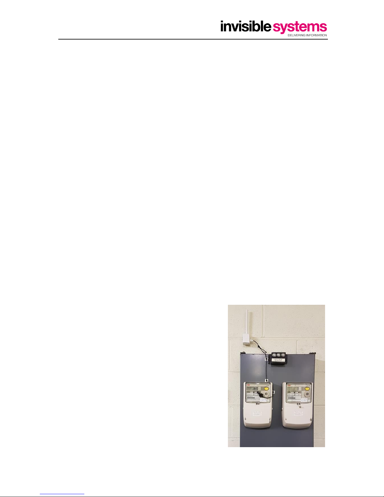
When placing sensors, avoid the following:
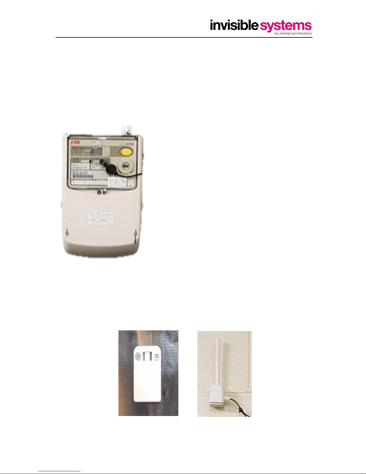
a. Placing the transmitter in metal enclosures (such as a distribution board, a fridge or a server
rack). In these cases, try to locate the sensor head (CT, temp probe etc) inside the enclosure
and lead the cable outside.
b. The transmitters are splashproof and are suitable for installation in outdoor areas, but are
not 100% waterproof. Do not install them in positions where they are liable to be
submerged.
c. Do not install the transmitters close to other RF sources such as alarm systems, door
openers or other radio systems. Although the amount of RF energy transmitted by the
sensors is very small indeed, there is a possibility that they could interfere with other
electrical devices, so they must not be installed close to other devices which could be
affected e.g. medical devices or wireless alarm systems.

Invisible Systems Limited P a g e | 8
7-9 Beetham Road, Milnthorpe Cumbria, LA7 7QL, England
Phone: 01539 722 520 Email: info@invisible-systems.com
QC0144 Optical Pulse Transmitter Installation Manual
When siting the gateway, try to ensure that the location is approximately equidistant in radio signal
terms from all the sensors.
Typically, sensors can be expected to pass through 4 –5 normal internal walls without difficulty.
The following illustration shows how sensors which are hidden behind large metal objects like tanks
or steel walls may have difficulty in transmitting to the gateway.
Notes
Care must be taken when installing this sensor as live electrical circuits are usually within
the vicinity. Seek to guidance of a qualified electrician if you are unsure.
Battery
For safety considerations, all wireless transmitters are transported with the internal battery
disconnected. Usually this can be confirmed if the white connector is passing through the base.
On first use it is therefore necessary to connect the battery
following the steps below:
1. Remove the four screws at the base of the sensor.
Then remove the base and the sealing gasket.
2. Carefully insert the small white plug into the PCB socket
and ensure the cable passes through the notch to avoid
pinching. See diagram below.
3. Replace the sealing gasket, cover and 4 screws. DO NOT
OVERTIGHTEN!
Possible
repeater
location

Invisible Systems Limited P a g e | 9
7-9 Beetham Road, Milnthorpe Cumbria, LA7 7QL, England
Phone: 01539 722 520 Email: info@invisible-systems.com
QC0144 Optical Pulse Transmitter Installation Manual
5. Checking operation
Following installation of the Optical Pulse transmitter, it is suggested that the operation is checked
to ensure the transmitter is being received by the Gateway.
Open Ultra RF Gateway Setup –This should be located on the desktop of your laptop.
On first use, if requested, select
the USB lead being used and
highlight for use.
Screen information being
displayed.
The Screen will show the transmitters it can see in range of the receiver, these can be sorted by
sensor type or ID as per preference.
Name lead
connection and
select it in drop
down list

Invisible Systems Limited P a g e | 10
7-9 Beetham Road, Milnthorpe Cumbria, LA7 7QL, England
Phone: 01539 722 520 Email: info@invisible-systems.com
QC0144 Optical Pulse Transmitter Installation Manual
Each Transmitter will show the following
1. Sensor ID
2. Transmitter Type
3. Battery Voltage
4. Values being received
5. Signal Strength and frequency
It is important to check all of this information to confirm that each sensor is being seen by the
gateway and at regular intervals in relation to (5). Blue colour dots show direct messages being
received and Orange colour dots show messages received via repeaters.
Correct setup and operation of Realtime-online, will require all the Sensor ID’s and Transmitter types
in conjunction with the Gateway ID.
The RSSI is shown in dBm with a bar chart showing signal strength. This is an important parameter.
The table below shows dBm ranges in relation to Signal strength.
The range shown above reads -100dBm this is shown in the table as a Marginal signal therefore will
need improving either by reviewing the transmitter location, moving the Gateway closer or adding a
signal repeater in between transmitter and receiver.
Value
RSSI
dBm
Signal
Strength
Value
RSSI
dBm
Signal
Strength
2
-109
Marginal
17
-79
Good
3
-107
Marginal
18
-77
Good
4
-105
Marginal
19
-75
Good
5
-103
Marginal
20
-73
Excellent
6
-101
Marginal
21
-71
Excellent
7
-99
Marginal
22
-69
Excellent
8
-97
Marginal
23
-67
Excellent
9
-95
Marginal
24
-65
Excellent
10
-93
OK
25
-63
Excellent
11
-91
OK
26
-61
Excellent
12
-89
OK
27
-59
Excellent
13
-87
OK
28
-57
Excellent
14
-85
OK
29
-55
Excellent
15
-83
Good
30
-53
Excellent
16
-81
Good
Further technical reference and product info can be obtained from associated data sheets

Invisible Systems Limited P a g e | 11
7-9 Beetham Road, Milnthorpe Cumbria, LA7 7QL, England
Phone: 01539 722 520 Email: info@invisible-systems.com
QC0144 Optical Pulse Transmitter Installation Manual
6. Dashboard configuration
Following successful login to Realtime-Online™ with your username and password, create new
sensor (System > Sensor Setup > Create New Sensor)
Enter Sensor ID number located on the side of the Optical Pulse Transmitter
Name the Senor as required with reference to site requirements for ease of identification.
Select Sensor Type = ‘Electric’ .
If you want this sensor to appear as the ‘incoming mains’ (displayed on the main dashboard front
page, tick ‘Mains’.
Select unit = ‘kWh’.
Select ‘Pulse 1’ from dropdown.
Enter the appropriate Pulse Factor. this is usually written on the face of the meter. E.g. if the meter
says ‘200 imp / kWh’ then the factor is 1/200 = 0.005
Click ‘Create Sensor’
Example:
6318030

Invisible Systems Limited P a g e | 12
7-9 Beetham Road, Milnthorpe Cumbria, LA7 7QL, England
Phone: 01539 722 520 Email: info@invisible-systems.com
QC0144 Optical Pulse Transmitter Installation Manual
7. Meter Validation
To confirm this meter readings will need to be taken at different intervals and entered into the
meter validation page on Realtime-Online(tm) to determine actual pulse rate.
Check meter validation(Reports>Meter Validation) then pick sensor ID that is fitted
Enter the reading obtained with date and time > Submit
This will need to be done twice as a minimum to allow the Realtime-online™ software to check the
readings. (the longer the time between reading the better the result). An initial check whilst on site
can be done with a few hours between readings however for full and accurate calibration, ideally 7
days between readings is desirable (48 hours minimum).
Click the two readings entered on the left of the screen and then Compare Readings the system will
then work out and validate the correct pulse ratio or suggest the correct one.
If the suggested pulse ratio is significatly diferent to the current Pulse Ratio the amend the Pulse
Factor in Sensor setup to help aid in the calibration of the equipment.
The more readings taken over time help prove correct operation.

Invisible Systems Limited P a g e | 13
7-9 Beetham Road, Milnthorpe Cumbria, LA7 7QL, England
Phone: 01539 722 520 Email: info@invisible-systems.com
QC0144 Optical Pulse Transmitter Installation Manual
8. Appendix 1 –Part Numbers.
Part Number
Item
Description
3999-913-2143
Ultra RF-Indoor Optical Pulse LED
Indoor single input pulse transmitter (2m)
3999-901-1212
Ultra RF Repeater
RF Signal Repeater Mains Powered
200-360-1001
Battery
3.6v Lithium with JST plug

Invisible Systems Limited P a g e | 14
7-9 Beetham Road, Milnthorpe Cumbria, LA7 7QL, England
Phone: 01539 722 520 Email: info@invisible-systems.com
QC0144 Optical Pulse Transmitter Installation Manual
Intentionally left blank

Invisible Systems Limited P a g e | 15
7-9 Beetham Road, Milnthorpe Cumbria, LA7 7QL, England
Phone: 01539 722 520 Email: info@invisible-systems.com
QC0144 Optical Pulse Transmitter Installation Manual
Table of contents