Involar MAC500 Series Operation instructions

INVOLAR Corporation, Ltd.
Tel: +86(0)02151098006 Fax: +86(0)2150277705
E-mail: info@INVOLAR.com
Web: www.INVOLAR.com
invo2
INVOLAR Grid-Connected Photovoltaic
Micro-Inverter
Model Number MAC500-XX
User Operating Manual
(Manual Version_1.12 MAC500-XX)
This manual is an integral part of the unit. Please read the instruction manual
carefully before installation, operation or maintenance. Keep this
instruction manual for future reference.

INVOLAR Corporation, Ltd.
Manual version 1.12 INVOLAR Corporation Ltd. Mar. 2016
2
Contact Information
INVOLAR Corporation Ltd
Power Lab, No.898 Laiting South Road, Shanghai, 201615, China
Tel:86-21-5109 8006
Fax: 86-21-5027 7705
www.INVOLAR.com

INVOLAR Corporation, Ltd.
Manual version 1.12 INVOLAR Corporation Ltd. Mar. 2016
3
Table of Contents
1READ THIS FIRST.................................................................................................................................................. 4
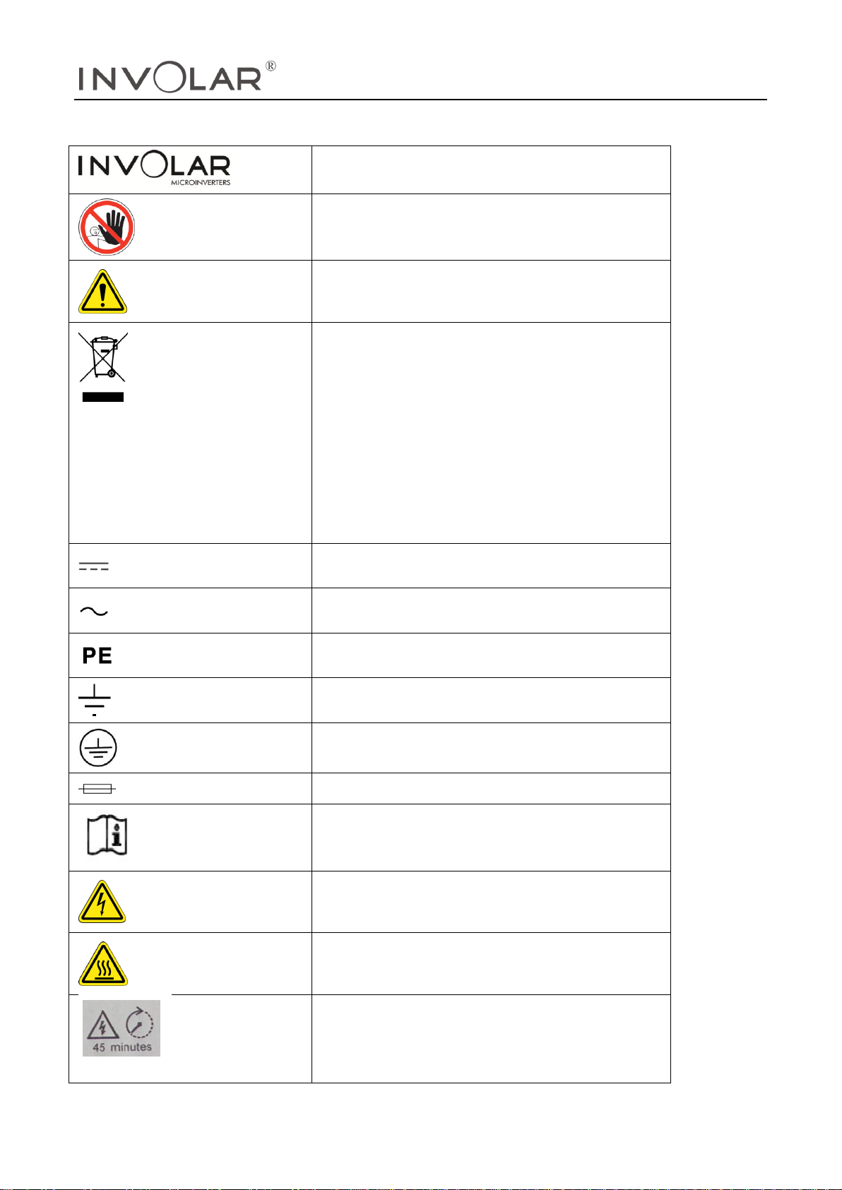
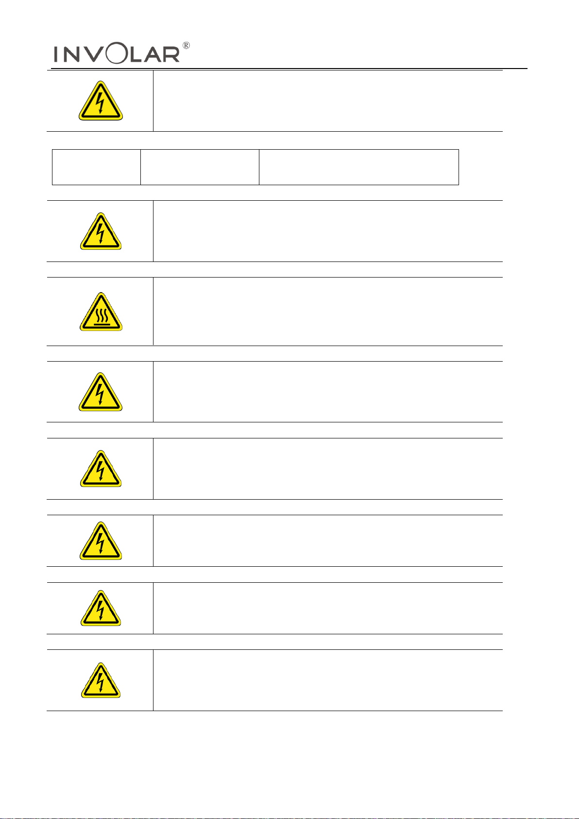
2SAFETY SYMBOLS............................................................................................................................................... 5
3SAFETY INSTRUCTIONSAND EC DIRECTIVES................................................................................................... 8
EC DIRECTIVES ................................................................................................................................12
4THE INVOLAR MICRO-INVERTER SYSTEM INSTRUCTION................................................................................20
THE INVOLAR MICRO-INVERTER SYSTEM........................................................................................20
THE INVOLAR MAC500...............................................................................................................20
FEATURES .........................................................................................................................................21
5INVOLAR MAC500INSTALLATION ......................................................................................................................22
5.1 INVOLAR MAC500OPERATIONAL ENVIRONMENT ..................................................................23
5.2 INVOLAR MAC500 OPERATIONAL CONDITION IN PV SYSTEM ...............................................24
5.3 INSTALLATION STEPS ...................................................................................................................24
5.4 INVOLAR MAC500 OUTSIDE DIMENSION ..............................................................................25
5.5 DETAILED INSTALLATION PROCEDURE.........................................................................................26
6. FUNCTION INSTRUCTIONS.................................................................................................................................31
WORKING MODE ............................................................................................................................31
GRIDCONNECTION .........................................................................................................................32
GRID DISCONNECT .........................................................................................................................32
START-UP CHECKS ...........................................................................................................................33
7DISCONNECTING A MICRO-INVERTER FROM THE PV MODULE.....................................................................34
8MONITORING AND TROUBLESHOOTING AND MAINTENANCE....................................................................35
SAFETY CHECKS................................................................................................................................35
MAINTAIN PERIODICALLY .................................................................................................................35
OVERVIEW.......................................................................................................................................36
MAC500 MICRO-INVERTER STATUS LED INDICATIONS AND ERROR REPORTING........................36
9INTERNET WEB....................................................................................................................................................39
USER REGISTRATION .........................................................................................................................39
USER LOGIN.....................................................................................................................................39
10 INVOLAR MAC500 MICRO-INVERTER TECHNICAL DATA...........................................................................40
TECHNICAL SPECIFICATIONS ............................................................................................................40
11 APPENDIX ..........................................................................................................................................................42
LIMITED WARRANTY .........................................................................................................................42
12. INVOLAR MAC500 MICRO-INVERTER SYSTEM WIRING DIAGRAM ......................................43

INVOLAR Corporation, Ltd.
Manual version 1.12 INVOLAR Corporation Ltd. Mar. 2016
4
IMPORTANT SAFETY
INSTRUCTIONS
SAVE THESE INSTRUCTIONS
1Read This First
This Micro-Inverter with a revolutionary technology maximizes the energy conversion from
photovoltaic solar modules, enhanced system reliability, and greatly simplifies the
installation and reduces the maintenance time and cost.
To reduce the risk of electrical shock, and to ensure the safe installation and operation of
the INVOLAR MAC500 Micro-Inverter, please read this manual carefully and pay attention
to the safety symbols appear throughout this document.
This manual is for end users.

INVOLAR Corporation, Ltd.
Manual version 1.12 INVOLAR Corporation Ltd. Mar. 2016
5
2Safety Symbols
Warnings and cautions tell you about the dangerous conditions thatmay occur
if you do not follow all instructions in this manual.
Please read following safety symbols which indicate dangerous conditions and
important safety instruction.
DANGER
The DANGER symbols in this manual and on MAC500
Micro-inverters indicate a hazard with a high level of risk
which if not avoided, will result in death or serious injury.
WARNING
The WARNING symbols in this manual and on
MAC500Micro-inverters
indicate a hazard with a medium level of riskwhich if
notavoided, could result in death or serious injury.
CAUTION
The CAUTION symbols in this manual and on MAC500
Micro-inverters indicate a hazard with a low level of risk
which if not avoided, could result in minor or moderate
injury.
NOTE
The NOTE symbols in this manual indicate important product information.

INVOLAR Corporation, Ltd.
Manual version 1.12 INVOLAR Corporation Ltd. Mar. 2016
6
Symbols replace words on the equipment, on a display, or in manuals.
Trademark
No access for unauthorized personnel
Caution, risk of danger
Symbol for the marking of electrical and
electronics devices according to Directive
2002/96/EC. Indicates that the device, accessories
and the packaging must not be disposed as
unsorted municipal waste and must be collected
separately at the end of the usage. Please follow
local ordinances or regulations for disposal or
contact an authorized representative of the
manufacturer for information concerning the
decommissioning of equipment.
Direct current
Alternating current
Protective conductor
Earth (ground) TERMINAL
Protective ConductorTerminal
Fuse
Refer to the operating instructions
Caution, risk of electric shock
Caution, hot surface temperature
RISK OF ELECTRIC SHOCK! Energy storage timed
Discharge: 45 minutes! Hazardous voltage present
for up to 45 minutes after disconnection from
power supply.

INVOLAR Corporation, Ltd.
Manual version 1.12 INVOLAR Corporation Ltd. Mar. 2016
7
Isc PV
Maximum short circuit current (DC) value which
the inverter is rated. This rating of the PCE refers to
the absolute maximum current the PV input of the
solar inverter is designed for under conditions of
expected use.
OVC
Overvoltage category (OVC)Designated
category to which the inverter voltage is deemed
suitably safe.
Vmax PV
Maximum rated (DC) input voltage value which
the inverter is rated. This rating of the PCE refers to
the absolute maximum voltage the PV input of the
solar inverter is designed for under conditions of
expected use.
CE mark is attached to the solar inverter to verify
that the unit follows the provisions of the European
Low Voltage and EMC Directives
PV
Photovoltaic
DC terminal, indicating the polarity of the
connections, positive,all positive connections shall
be marked with Redinsulated wire.
DC terminal, indicating the polarity of the
connections, negative, all negative connections
shall be marked with black insulated wires.
PCS
Power conversion equipment, hereby is our
DC/AC inverter
Service Personnel
A person having appropriate technical training
and experience necessary to be aware of hazards
to which that person may be exposed in
performing a task and of measures to minimize the
risks to that person or other persons
Qualified
CompetentPersonnel
Person adequately advised or supervised by an
electrically skilled person to enable him or her to
perceive risks and to avoid hazards which
electricity can create. For the purpose of the
safety information of this manual, a "qualified
person" is someone who is familiar with
requirements for safety, refrigeration system and
EMC and is authorized to energize, ground, and
tag equipment, systems, and circuits in
accordance with established safety procedures.
The INVOLAR inverter system may only be
commissioned and operated by competent
personnel.

INVOLAR Corporation, Ltd.
Manual version 1.12 INVOLAR Corporation Ltd. Mar. 2016
8
DVC
Decisive voltage class
Closed Electrical Operating
Area
Room or location for electrical equipment to
which access is restricted to skilled or instructed
persons by the opening of a door or the removal
of a barrier by the use of a key or tool and
which is clearly marked by appropriate warning
signs
Technical Competence
The procedures described in this manual should be
performed by trained competent personnel only.
Maintenance should only be undertaken bycompetent
individuals who have a general knowledge of and
experience with devices ofthis nature. No repairs
should ever be undertaken or attempted by anyone
not havingsuch competency.
Compliance with safety regulations depends upon installing and configuring system
correctly, including using the specified wirings. The system must be installed only by
professional assemblers who are familiar with requirements for safety, Photovoltaicsystem
and EMC. The assembler is responsible for ensuring that the end system complies with all the
relevant laws in the country where it is to be used.
INVOLAR requires using only genuine replacement parts,manufactured or sold by INVOLAR.
Read completely through each step in every procedure before starting the procedure;any
exceptions may result in a failure to properly and safely complete the attemptedprocedure.
The individual sub-assembly of the system shall be interconnected by means of the wiring
methods outlined in national/international regulations but not limited to the BS7671
Requirements/ VDE regulation 0107.
All electrical installations must be made in accordance with the NationalElectrical
regulations, and any other codes and regulationsapplicable to the installation site.
Servicing of this product in accordance with this manualshould never be undertaken in the
absence of proper tools, test equipment andthe most recent revision to this manual which is
clearly and thoroughlyunderstood.
3Safety Instructionsand EC Directives
This chapter contains the safety instructions which you must follow when installing, operating
and servicing the unit.If ignored, physical injury or death may follow, or damage may occur
to the unit. Read the safetyinstructions before you commence work on the unit. If you are
unable to understand the Dangers, Warnings, Cautions or Instructions, contact the
manufacturer or an authorized servicedealer before installing, operating and servicing the
unit.
For INVOLAR Micro-Inverter Warranty Terms and Conditions, see the appendix of this
manual.
SAVE THESE INSTRUCTIONS- This manual contains important instructions for the

INVOLAR Corporation, Ltd.
Manual version 1.12 INVOLAR Corporation Ltd. Mar. 2016
9
MAC500 that shall be followed during installation and maintenance.
Be aware that only competent personnel should install and /or replace INVOLAR
Micro-Inverters.
Perform all electrical installations in accordance with all local electrical codes.
Compliance with the rules of correct use of tools and personal protective equipment
(PPE) ensuring a safe installation.
The inverter can still be chargedwith a hazardous voltage after being disconnected
from the supply. Allow a 45 minute discharge period before working on the inverter.
Be aware that only competent personnel should maintain INVOLAR Micro-Inverter.
Connect the INVOLAR Micro-Inverter to the electrical utility grid only after receiving
prior approval from the utility company.
During the day time, use opaque covering on PV array to screen the sunshine before
installing the INVOLAR Micro-Inverter, thus eliminating the risk of electric shock to
persons working on the system.
The photovoltaic micro-inverter is not intended to be secured to the back of the
photovoltaic module. Itshould be secured to the framework supporting the PV
module.
MAC500 is intended to be connected only to a dedicated branch circuit.
The device is not provided with ground-fault detector/interrupter unit.
WARNING
Always disconnect the unit from the MAINS and PV supply by the
external customer installed disconnecting devices before
installation, servicing and maintenance works, and placed a
warning sign adjacent to switch “do not turn on maintenance in
progress”.
WARNING
PV arrays become energized when exposed to light.Use safe
working practices whenworking on PV arrays as both AC and DC
can be present.
CAUTION!
The device is intended for fixed installation. Located on a part
that is not removable without shutdown to the operation of the
unit.
WARNING
Risk of electric shock, Do not open cover. No user serviceable
parts inside. Servicing limited to competent service personnel.

INVOLAR Corporation, Ltd.
Manual version 1.12 INVOLAR Corporation Ltd. Mar. 2016
10
WARNING
Do not use fuseswhich are not approved by the manufacturer.
They should be of same type and rating value as specified
Only competent personsshould replace the fuse.
AC fuse (F2,F3)
Littelfuse
215; AC 250V, 3.15A, 5×20mm, rated
breaking capacity: 1500A
WARNING
Risk of electric shock –Both A.C. and D.C. voltage sources are
terminated inside this device. Each circuit must be individually
disconnected before servicing.
WARNING
Hot surfaces –To reduce the risk of burns –Do not touch device
surface when the device is running.
Allow 30 minutes cooling down period after switch off before
handling the device.
WARNING
Risk of electric shock from energy stored in capacitor! Do not
remove cover until 45 minutes after disconnecting all sources of
supply.
WARNING
The printed circuit boards contain components sensitive to
electrostatic discharge. Wear a grounding wrist band when
handling the boards. Do not touch the boards unnecessarily.
WARNING
Do not operate device if found to be damaged or lacking parts.
WARNING
Before installing the unit, obtain approval from the utility
company.
WARNING
Ensure adequate spacing distances between the unit and other
equipment or structures.Ensure that air can pass freely around the
unit for heat dissipation and maintenance accessibility.

INVOLAR Corporation, Ltd.
Manual version 1.12 INVOLAR Corporation Ltd. Mar. 2016
11
DANGER
This photovoltaic micro-inverter is only for use in a closed
electrical operating area! The device shall not be energized
during installation or maintenance!
An internal isolation transformer is provided in the micro-inverter, internal transformer is
galvanic isolation from the MAINS and PV array by reinforced insulation. PV input circuit is
earthed, and non-earthed pole of PV input keeps basic insulation isolation from earthed
metal.
In accordance to EN 62109-1:2010, circuits complying with the requirements for DVC-A are
considered safe to touch, however, since the device is intended for outdoor use and Vmax
PV is rated 50V D.C, which exceeds maximum 35V DC limit for DVC-A in WET LOCATION as
below:
Summary of the limits of the decisive voltage classes
The inverter and PV array are restricted for use in a CLOSED ELECTRICAL OPERATING AREA!
WARNING:
The grid connected inverter is intended to be used with
appropriate PV generator,switch gear, SPDs, distribution board,
electrical protection components and other device to form
complete end systems. Compliance with safety regulations
depends upon installing and configuring inverter correctly,
including using the specified emergency stop device adjacent
to solar inverter. The unit must be installed only by professional
assemblers who are familiar with requirements for safety and

INVOLAR Corporation, Ltd.
Manual version 1.12 INVOLAR Corporation Ltd. Mar. 2016
12
EMC. The assembler is responsible for ensuring that the end
product or system complies with all the relevant laws in the
country where it is to be used.
WARNING:
Fire hazard. Suitable for mounting on concrete or other
non-combustible surface only.
WARNING:
Be aware that the input DC voltage of the INVOLAR
Micro-Inverter shall not exceed 50V, higher voltage may
cause permanent damage to the device; it contains no user
serviceable and INVOLAR-Micro-Inverter Warranty parts.
WARNING:
This unit is not provided with a GFDI device. The inverter must
be fitted with an external device as required by the Article 690
of the National Electrical Code for the Installation location.
WARNING:
The device is not provided with automatic disconnecting
means –this device shall be provided with external relaying
protection in accordance with local codes and local utility
requirements.
WARNING:
To reduce the risk of fire, do not connect to an ac load centre
(circuit breaker panel) having multi-wire branch circuits
connected
CAUTION:
To reduce the risk of fire, connect only to a circuit provided
with 16 amperes maximum branch-circuit overcurrent
protection in accordance with local codes and local utility
requirements.
CAUTION:
Final circuit over current protection of the AC circuit shall be
provided by others and should be suitable for system design.
EC Directives
This chapter follows the requirements of the European Low Voltage
Directives,contains the safety instructions and conditions of acceptability for the
standard, which you must follow when installing, operating and servicing the unit. If

INVOLAR Corporation, Ltd.
Manual version 1.12 INVOLAR Corporation Ltd. Mar. 2016
13
ignored, physical injury or death may follow, or damage may occur to the unit.
Read these instructions before you work on the unit. If you are unable to understand
the Dangers, Warnings, Cautions or Instructions, contact the manufacturer or an
authorized service dealer before installing, operating and servicing the unit.
The Grid Connected Inverter meets the requirements stipulated in Low Voltage
Directive (LVD) 2006/95/EC and Electromagnetic Compatibility (EMC) Directive
2004/108/EC. The unit is tested based on:
EN 62109-1:
EN 61000-6-1;
EN61000-6-2;
EN61000-6-3;
UL1741/IEEE1547
When installing the PV system, startup of the unit (i.e. start of designated operation) is
prohibited until it is determined that the full system meets the requirements stipulated
in the EC Directive (2006/95/EC, 2004/108/EC etc).
The grid connected Inverterleaves the factory completely connecting device and
ready for connection to the mains and PV supply. The unit shall be installed in
accordance with national wiring regulations. Compliance with safety regulations
depends upon installing and configuring system correctly, including using the
specified wirings. The system must be installed only by competent assemblers who
are familiar with requirements for safety and EMC. The assembler is responsible for
ensuring that the end system complies with all the relevant laws in the country where
it is to be used.
The individual subassembly of the system shall be interconnected by means of the
wiring methods outlined in national/international regulations but not limited to the
BS7671 Requirements/ VDE regulation 0107.
[Use Condition]
1. Overvoltage category:overvoltage category III for MAINS connection,
overvoltage category II for PV supply according to IEC/EN 60664-1.
2. Pollution degree: Pollution degree III, not intended for heavy pollution of the air by
dust, smoke, corrosive or radioactive particles, vapors or salt.
3. Class of protection: I.
4. Protection against ingress of water: IP65
WARNINGS
The Degree of protection rating IP65 to IEC 60529 is applicable to
the device when the supplied installation connectors are inserted
correctly, and suitable external cord was fitted. If the unit is not
connected in this way, hazardous live parts may be exposed and
the IP Rating of the unit will be invalid
5. The equipment is rated to operate at an altitude less than 2000 m.

INVOLAR Corporation, Ltd.
Manual version 1.12 INVOLAR Corporation Ltd. Mar. 2016
14
6. Installation:
Equipment not suitable for use in the presence of explosive gases.
Equipment not suitable for use in the presence of flammable gases or liquids.
Not suitable for use in the presence of Exposure to strong electric or magnetic fields
Not suitable for use in the presence of Exposure to heavy vibration and shocks
Not suitable for use by untrained personnel.
7. The unit is suitable for connection to a MAINS circuit capable of delivering not
more than 160 rms symmetrical Amperes. The absolute maximum total PV array short
circuit current (D.C.) that the inverter is rated to have connected to its PV input,
under worst-case conditions of ambient temperature, irradiance, shall be less than
12A.
8. Supply earthing systems and system voltage: TN-C-S, 120/240V (L to N/ L to L)
9.PV modules for non-isolated inverters: PV modules shall have an IEC 61730 Class A
rating, PV modules must have a maximum system voltage rating based upon the AC
mains voltage.
[Surge Protective Devices (SPDs) for PV installation]
Over-voltage protection with surge arresters should be provided when the PV power
system is installed.
The grid connected inverter is not fitted with SPDs in both PV input side and MAINS
side.
Lightning can cause damage either from a direct strike or from surges due to a
nearby strike. Induced surges are the more likely cause of lightning damage in the
majority of installations, especially in rural areas where electricity supplies are usually
by long overhead lines. Surges may be induced on both the PV array conductors
and the A.C. cables leading to the building.
Specialists in lightning protection should be consulted during the endues
application.
Using appropriate external lightning protection, the effect of a direct lightning strike
into a building can be mitigated in a controlled way, and the lightning current can
be discharged into the ground.
Installation of SPDs to protect the inverter against mechanical damage and
excessive stress include a surge arrester in case of a building with external lightning
protection system(LPS) when separation distance s is kept:
To protect the D.C. system, surge suppression devices (SPD Type 2) should be fitted
at the inverter end of the D.C. cabling and at the array, located between the
inverter and the PV generator, if the voltage protection level (VP) of the surge
arresters is greater than 1100 V, anadditional SPD Type 3 required for surge
protection for electrical devices.

INVOLAR Corporation, Ltd.
Manual version 1.12 INVOLAR Corporation Ltd. Mar. 2016
15
To protect the A.C. system, surge suppression devices(SPD, type 2) should be fitted
at the main incoming point of A.C. supply (at the consumer’s cut-out), located
between the inverter and the meter/distribution system;
SPD (test impulse D1) for signal line according to EN 61643-21
All D.C. cables should be installed to provide as short run as possible, positive and
negative cables of the same string or main DC supply should be bundled together,
avoiding the creation of loops in the system.
This requirement for short runs and bundling includes any associated earth/bonding
conductors.
[Selection of fuse and cables]
Mains cable (AC line cable) shall be short circuit protected and thermal overload
protected.
Always fit the input cable with fuses. Normal gG (US: CC or T) fuses will protect the
input cable in shortcircuit situations. They will also prevent damage to adjoining
equipment.
Dimension the fuses according to local safety regulations, appropriate input voltage
and the rated current of the solar inverter.
AC output protected by external fuse (gG, rated current 16 A/ 250 VAC), provided
in all live connections to the AC supply.
The rated shortcircuit breaking capacity of the above protective device shall be at
least equal to the prospective fault current at the point of installation. See section
technical data of this manual for details.
AC output cables: Cu, (L,N+PE, 2x2,5+2,5mm2with a max length of 2m and
operating time of the fuse is less than 5 seconds, installation method B2 according to
EN 60204-1: 2006, annex D: cable in conduit cable trucking system, number of
loaded circuit only one. Use 90 °C wire for ambient temperature between 40 °C and
65 °C.
NOTE
For conditions differing from those mentioned above,
dimension the cablesaccording to local safety
regulations, appropriate input voltage and the load
current of the unit. (You can choose a thicker cable but
the fuses must be rated according to the table.)
NOTE
Fuses must be approved by notified body.
Inverter is provided galvanic isolation from the MAINS to
the PV array, backfeed current to the array is not

INVOLAR Corporation, Ltd.
Manual version 1.12 INVOLAR Corporation Ltd. Mar. 2016
16
considered. However, DC side current is about 20,4A and
decrease to 0A within 20.4ms under the PV input short
circuit condition. Therefore, the current-carrying capacity
of the components and sub-assemblies provided in the
end-use system (connectors, cables, junction box,
switchgear, etc.) and the reverse current PV module shall
be considered based on back feed current and reverse
current. The direct current (DC) circuit breaker or fuse
between each solar generator and inverter shall be
provided based on solar inverter input ratings.
Select DC cables based on the above inverter back feed
current and Isc PV rating and Vmax ratings.
[Isolation Device]
The inverter is not provided with isolation device.
However, as a complete assembly or system, the unit requires that the customer
shall supply external fuses and isolation device. This is not only good practice based
on safety consideration, but is a mandatory requirement as a license condition of an
approved equipment. A manual AC switch disconnectorand DC switch
disconnectormust beprovided located in an accessible position.
Please check the unit nameplate and run ample capacity. A suitably rated Isolating
Switch (this is also an option that could be selected) should be fitted immediately
adjacent to each unit and installed both for AC output and DC input.
All incoming phase lines and neutral conductors and PV generator cables are to be
suitably fused at the Sub-Board to protect the installed wiring and the unit.
During installation, care should be taken to ensure that:
–An appropriate approved disconnect device shall be provided as part of PV
system;installation which shall disconnect simultaneously all live conductors of mains
supply.
–An appropriate approved disconnect device shall be provided as part of the
device;installation which shall disconnect simultaneously all PV input conductors of
PVgenerator.
–The disconnect devices are positioned in close proximity to the equipment and is
easily accessible to the operator.
–It is clearly marked as a disconnect device for the solar inverter unit.
Therefore, install separately a hand operated input disconnecting device (means)
between the PV generator and inverter, between MAINS and inverter. The
disconnecting devices must be of a type that can be locked to the open position
during installation and maintenance work, and constructed to disconnect all live
conductors of its power supply circuit.
Place a warning sign “do not turn on – maintenance in progress” on the external

INVOLAR Corporation, Ltd.
Manual version 1.12 INVOLAR Corporation Ltd. Mar. 2016
17
disconnecting switch when it is shut down, and make sure that on/off remote
controls are inhibited.
Dual supply labeling should be provided at the service termination, meter position
and all points of isolation to indicate the presence of onsite generation and
indicating the position of the main A.C. switch disconnector.
[Emergency Stop Devices]
For safety reasons, install the emergency stop devices at station adjacent to solar
inverter combiner in the endsystem.
The emergency stop of the unit can be enabled using the service switch as required
in section [Isolation device] if this isolation device is installed adjacent to solar
inverter.
[PE Connection and LeakageCurrent]
The endues application shall monitoring of the protective conductor by a residual
current operated protective device (RCD) with rated fault current Ifn ≤30mA which
automatically disconnects the device in the case of a fault.
WARNINGS
EARTH CONNECTION ESSENTIAL BEFORE CONNECTING SUPPLY
Incorrect grounding can cause physical injury, death or equipment
malfunction and increase electromagnetic interference.
Make sure that grounding conductors are adequately sized as
required by safety regulations.
Do not connect the ground terminals of the unit in series in case of a
multiple installation.
WARNINGS
This product can cause current with an A.C. component. Where a
residual currentoperated protective (RCD) or monitoring (RCM) device
is used for protection in case of direct or indirect contact, only an RCD
or RCM of Type B is allowed on the supply side of this product.
[Safety Check]
The following safety checks should be performed at least every 12 months by
manufacturer’s qualified person who has adequate training, knowledge, and
practical experience to perform these tests. The data should be recorded in an
equipment log. If the device is not functioning properly or fails any of tests, the
device has to be repaired.

INVOLAR Corporation, Ltd.
Manual version 1.12 INVOLAR Corporation Ltd. Mar. 2016
18
1. Inspect the equipment and accessories for mechanical and functional damage.
2. Inspect the safety relevant labels for legibility.
3. Inspect the fuse to verify compliance with rated current and breaking
characteristics.
4. Verify that the device functions properly as described in the instructions for use.
5. Verify that the current/voltage sensors functions properly.
6. Verify software or firmware that performs safety critical application functions
properly.
7. Check earth connection, retightening of terminals.
8. Check the following safety parameters which are factory set and fixed per IEC
62116:2008 and IEC 61727:2004,this trip point is factory set and fixed, user cannot
change this parameter.
Exceeding this limit will trigger de-energized-to-trip system and alarm within time as
specified in the following tables.
9. Measurement of insulation resistance, consult manufacturer.
10. Measurement of earth resistance, consult manufacturer.
11. Mounting structures: Verify tightness and integrity of bolts and other fastening
devices;Verify if there is significant corrosion
12. Using manufacturer’s procedures and/or technical data on an “as-needed”
basis when performing periodic component calibrations.
Consult manufacturer for safety check procedure.
[Interface Protection and Inverter Set Points]

INVOLAR Corporation, Ltd.
Manual version 1.12 INVOLAR Corporation Ltd. Mar. 2016
19
Incorporated interface protection is designed according to IEC 61727:2004 and IEC
62116:2008,it is insensitive to normal voltage and frequency variations in the
distribution network.
The interface protection ensures that the inverter cease to energize the distribution
network when any parameters listed as below exceeds the applied operating
setting. Disconnection is provided in case of any hardware malfunctioning.
The solar inverter will cease to energize the network in response to an interface
protection; however, this is not achieved by disconnecting means between inverter
and grid.
Default interface protection settings
WARNINGS
Alteration of the above settings or full setting range of the interface
protection may cause a breach of the type-certificate
marking.Unauthorized access to factory safety parameters setting and
software is prohibited.
A reset to the factory safety parameters requires retesting and verification in
conjunction with the end-use system.

INVOLAR Corporation, Ltd.
Manual version 1.12 INVOLAR Corporation Ltd. Mar. 2016
20
4The INVOLAR Micro-Inverter System Instruction
The INVOLAR Micro-Inverter System
The three key elements of an INVOLAR Micro-Inverter System are:
The INVOLAR Micro-Inverter
The INVOLAR eLog communication gateway
The INVOLAR SDEDAS/SELITE web-based monitoring and analysis
PV module
The INVOLAR Micro-Inverter maximizes energy production from the PV
array. Each INVOLAR MAC500 is connected to two PV modules. (See
Figure 4-1 this figure should be updated with new connection diagram)
This unique configuration means that a Maximum Peak Power Point
Tracker (MPPT) controls each PV module. The INVOLAR MAC500 ensures
top performance for its associated PV module although individual PV
modules in the array may be affected by shading, soiling, orientation, or
PV module aging. This insures that the maximum power available from
each PV module with a consequent up to 25% more energy production.
The distributed nature of the INVOLAR Micro-Inverter System insures that
there is no single point of system failure in the PV system.
Energy
Terminal
Unit
SEDAS-Internet
server
Broadband
router
L N PE
MAC500 MAC500
MAC500
Local
PC
Meter
P V P V
MAC500
Customer
web terminal
P V P V
P V P V
P V P V
Figure4-1 The INVOLAR Micro-Inverter System
NOTE
The INVOLAR eLog communication gateway, the INVOLAR LCF(Line
Communication Filter) and the INVOLAR SEDAS/SELITE(Solar Energy
Data Acquisition System) are optional elements, before installing
these elements, read all instruction and cautionary marking in the
related user manual.
The INVOLAR MAC500
By adopting high frequency DC link topology (Figure 4-2) and dual –DSP controller,
Table of contents
Other Involar Inverter manuals