INVT EVC16 Series User manual

1
EVC16 Series of electric vehicle AC power supply charger
Installation and Operation Manual
EVC16-AW7KGP1UE
EVC16-AW11KGP1UE
EVC16-AW22KGP1UE
Document version V1.0

2
Copyright Information
All the content presented and picture marks in this manual is the legal copyright of INVT Electric Vehicle Drive Technology Co., LTD.
Without the authorization of the person in this company, no one shall copy, extract or otherwise use the above content. If you are
authorized to use the content in this manual, you must use it within the scope of authorization, and indicate the "source of content".
We reserved the right of pursue relevant legal responsibilities if there is any violation of the above statement.
Disclaimer of Warranties and Limitation of Liabilities
The specifications,illustrations and information in this manual are based on the latest data provided by the technician. INVT reserves
the right to update manual without timely notice. The information in this manual has been strictly checked for accuracy, but no
guarantee is given for the completeness of its content, including but not limited to product specifications, features and illustrations.
INVT shall not be liable for any direct, special, incidental or indirect damages or any damages of economic consequence .(including
loss of profits)
IMPORTANT
Before operating or maintaining this charger, please read this manual carefully, paying extra attention to the safety warnings and
precautions.

3
Safety Information
In order to ensure the safety of yourself and others, and to prevent your vehicle and charger damaged, be sure to strictly read and
follow the instructions and warning statements in this manual to operate the charger. It’s of great importance that the children
forbidden to operate this machine. The parents need to monitor the children when they stay around the charger.
DANGER
Indicated the danger information, the operator must avoid these unsafe factors, and operate it according to the local standard .
Otherwise, you may get serious injured and other losses.
WARNING
Indicates a potentially harmful situation, you must prevent it from harm yourself by comply with the relevant standards , otherwise it
could result in serious injury and losses
Safety Instructions
The following safety warnings covers most of situations that INVT get to know. INVT cannot show or predict or advise you as all of
the possible warnings. You must be certain confirm the operation procedure to ensure your personal safety and charger working
normally.
SAFETY WARNINGS
The engineers who install the chargers must have the electrical licensed that meet the requirements of local laws and
regulations
Ensure the chargers are grounded securely and reliably, and the ground connections comply with local standards and criterion.
Do not install or use this Charger near flammable, explosive, harsh, or combustible materials, chemicals or vapors.
Children should be supervised when around this Charger. And forbidden to operate.
Do not insert fingers or foreign objects into the electric vehicle connector.
Do not use the Charger if the flexible power cord or EV cable is frayed, broken or otherwise damaged.
Do not use the Charger if the enclosure or the EV connector is frayed, broken or otherwise damaged.
Recommend to use 105℃wire copper conductors (UL1015) .
Do not operate the Charger outside its operating temperature range of -13 to 131 °F (-25 to 55 °C).
Incorrect installation and testing of the Charger could potentially damage the vehicle's battery, components, or the Charger
itself.
Handle the Charger with care during transportation. Do not subject it to strong force or impact or pull to prevent damage to it or
other components.

4
Catalogue
Catalogue ..........................................................................................4
1. About this manual .................................................................................5
1.1 Using this manual ........................................................................... 5
1.2 Applicable areas .............................................................................5
1.3 Applicable group .............................................................................5
1.4 Illustration .................................................................................. 5
1.5 How to use this manual .......................................................................5
1.6 General Introduction ......................................................................... 5
1.7 Abbreviations and terms ...................................................................... 6
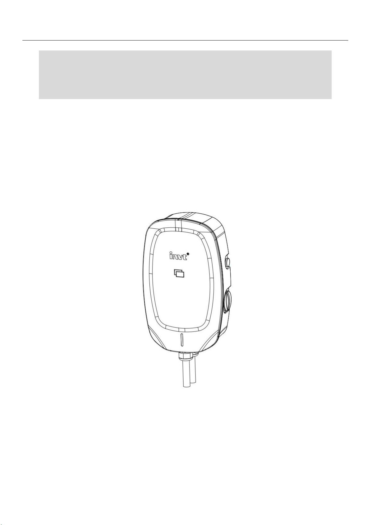
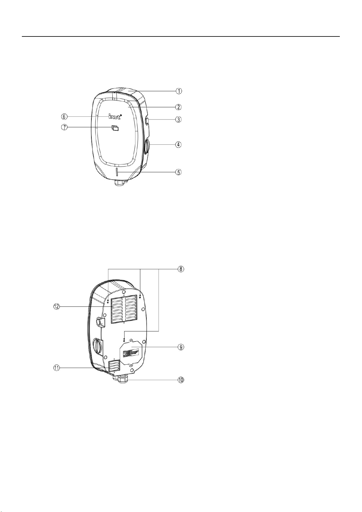
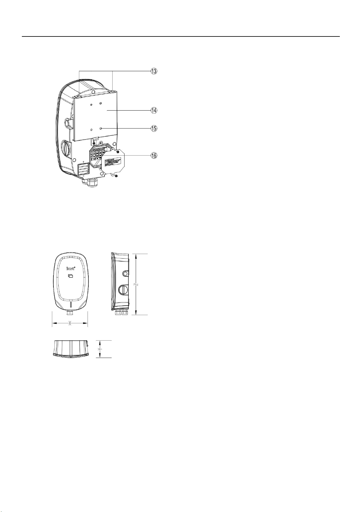
1.8 Product Overview ............................................................................7
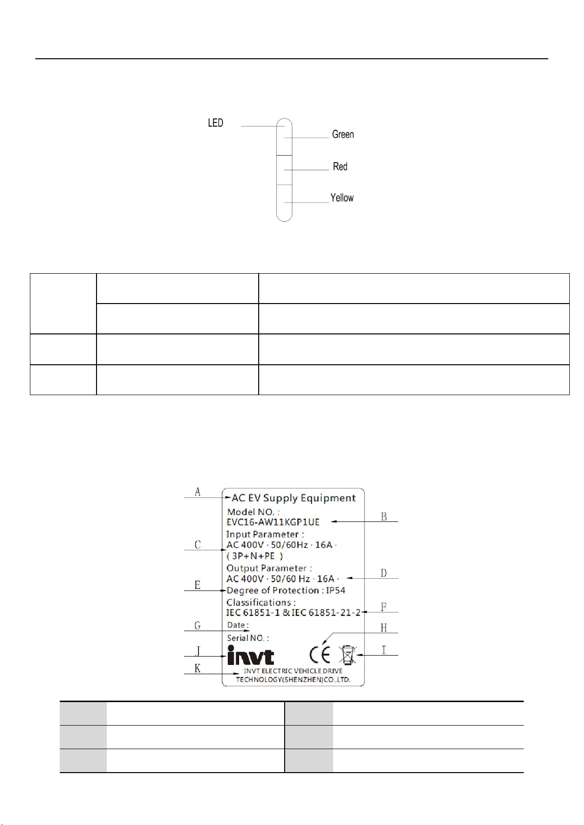
1.9 LED indicators .............................................................................. 9
2. Specifications .................................................................................... 9
2.1 Product name plate .......................................................................... 9
2.2 Product technical parameters ................................................................. 10
3. Preparation for Charger installation ................................................................. 12
3.1 General requirements ........................................................................ 12
3.2. Environment and tool requirements ............................................................12
3.3 Unpack the Charger ......................................................................... 12
4. Electrical installation of the Charger ................................................................. 12
4.1 General Specification ........................................................................ 12
4.2 Electrical installation procedure ................................................................ 14
5. Mechanical installation of the Charger ............................................................... 16
5.1 Installation procedure of power distribution module (Optional) ..................................... 16
(1) Cable hole pre-treatment ..................................................................16
(2) Power distribution module cable connection ................................................. 16
5.2 General Specification ........................................................................ 17
5.3 Support rear plate mounting ...................................................................18
5.4 Hanging ear installation ...................................................................... 19
5.5 Installation of the whole Charger ............................................................... 19
5.6 End and check .............................................................................. 19
6. Charger power supply operation .................................................................... 20
6.1 Power on operation .......................................................................... 20
6.2 Close the Charger power switch ............................................................... 20
6.3 Power-off operation .......................................................................... 21
7. Daily maintenance and fault diagnosis ............................................................... 21
7.1 Daily maintenance ........................................................................... 21
7.2 Fault diagnosis .............................................................................. 21

1. About this manual
1.1 Using this manual
This manual is only applicable to the installation and operation of EVC16 series 7KW,11KW and 22kW AC power supply
Charger.
This manual provides the information required to perform the following work:
Installation work of the charger.
Daily fault diagnosis and maintenance of the charger.
The manual may be updated with the product upgrade iteration, but the change may not affect the normal reading and execution
of the user.
1.2 Applicable areas
This manual is applicable to the EU Community countries and other areas that use charging standard IEC61851-1&
IEC61851-21-2.
1.3 Applicable group
This manual is designed for the qualified engineers with electrical license.
In addition to being used by professional engineers, users can also strictly follow the process described in this document to
perform simple maintenance.
1.4 Illustration
The illustrations in this document have show most of the product information include some normal functions and typical
settings of the product.
1.5 How to use this manual
Ensure that you understand all the contents of this manual is the prerequisite for your correction use .
Please read the safety section carefully to ensure that you understand all the safety instructions.
1.6 General Introduction
The INVT EVC16 series EV charger is designed to charge a electric vehicle or a hybrid plug in electric vehicle at your home or
apartment. Our chargers provide you with safe, reliable, fast, and smart charging solutions. The difference between the INVT 7KW,
11KW, 22KW AC EV charger is that the single phase or three phase electrical installation, while the latter 11KW and 22KW support
400V voltage input. The installation procedures for the three models are almost the same.This manual describing the installation
steps both single phase and three phase input. This manual will instruct you how to install and use this charger. You can access
chargers to the Internet through WIFI, control chargers and check running information on your phone APP.
Intended Use
The INVT AC EV charger for home is intended for the AC charging of EV. It is intended for both indoor and outdoor use.
Note: The images and illustrations description in this manual may differ slightly from the actual ones

6
1.7 Abbreviations and terms
Abbreviations
Definition
AC
Alternating current power supply
DC
Direct current power supply
EMC
Electromagnetic compatibility
EV
Electric vehicle
EVSE
Electric vehicle power supply Charger
RFID
Radio frequency identification
PE
Protective ground
Note: All terms may not be explained in this manual, which may help the engineer understand the operation about the Charger.

7
1.8 Product Overview
8 Mounting hole
9 Rear maintenance cover plate
10 Bottom AC inlet and outlet hole
11 Heat dissipation air inlet
12 Heat dissipation air outlet
1 Charger main body cover
2 Front cover plate
3 Emergency stop button
4 Maintenance hole
5 Indicator
6 Manufacturer Logo
7 RFID Reader
Note: Heat dissipation fan is only equip on the 22KW charger.

8
X Width of the charger
Y Depth of the charger
Z Height of the charger
X: 230 mm Y: 115 mm Z: 375 mm
13 Mounting bracket
14 Rear plate
15 Wall installation hole
16 AC wire connector

9
9 LED indicator
Green
Solid Green
The charger is on standby / A charging session has ended
Not illuminated
The charger is off
RED
Solid Green and Red
The charger has a faulty
Yellow
Solid Yellow and Green
The charger is charging the vehicle
2. Specifications
2.1 Product name plate
A
Product name
G
Production date and bar code
B
Product model
H
CE identification
C
Input characteristics
I
Recyclable Mark

10
D
Output characteristics
J
Manufacturer LOGO
E
Protection degree
K
Company name
F
Implementation standards
-
-
Note: The data in the figure is only a reference and does not represent the physical nameplate of the product. To view
the applicable data, find the nameplate on the charger.
2.2 Product technical parameters
Electrical parameters
Model
EVC16-AW7KGP1UE
EVC16-AW11KGP1UE
EVC16-AW22KGP1UE
Comment
Input
parameters
Input
mode
Single-phase
three-wire
Three-phase five-wire
Note: The
product is
suitable for T-N
system.
Voltage
range
230Vac±10%
400Vac±10%
Note: The
product works
normally within
this voltage
range.
Frequency
range
45~65 Hz
-
Rated
frequency
50/60 Hz
-
Rated
voltage
230Vac
400Vac
-
Rated
current
≤32A
≤16A
≤32A
-
Output
parameters
Rated
voltage
230Vac
400Vac
Note: The output
voltage varies
with the input
voltage.
Rated
current
≤32A
≤16A
≤32A
-
Rated
power
7 kW
11 kW
22 kW
-
Power factor
≥0.99
Rating condition
Efficiency
≥99.5%
Rating condition
Standby power consumption
≤5 W
Rating condition
Current measurement range
10mA~50A;±0.5%
10mA~25A;±0.5%
10mA~50A;±0.5%
-
Accuracy class
Level 1.0
-
Input protection type
Type A RCD;≤30mA
-
Protective function
Leakage current protection; Over current protection; Short circuit
protection; Detection gun disconnection protection; Grounding protection,
Note: Lightning
protection for its

11
over-voltage and under-voltage protection ; Load imbalance protection(only
applies to three-phase five-wire).
own control core.
Input connector
3 Pin terminal
5 Pin terminal
Note:8~10 AWG
Charge
interface
Quantity
one
-
Length
Charging gun wire , total length 5m(including 0.3m)
Note:
Customizable.
Type
EN IEC 62196-2016 : AC Type 2
-
Insulation
resistance
Input to
Output
Under normal atmospheric pressure , in the environment of relative
humidity ≤ 90% ,the insulation resistance between each live circuit and
between the live circuits and the ground is not less than 10MΩ at 1000V DC
voltage.
-
Input to PE
Output
to PE
Withstand
voltage
Input to
Output
AC2500V/1min/10mA
-
Input to PE
AC2500V/1min/10mA
-
Output
to PE
AC2500V/1min/10mA
-
Leakage
current
<5mA(230V ac /400V ac 、50/60Hz input)
-
System parameters
Standby power
<5W
-
Shell Material
Plastic (ABS+PC)
-
Panel Material
Plastic (ABS+PC)
-
Appearance Size
width* height*depth:230*375*115(mm)
Tolerance ±2mm.
Network communication
2.4G WIFI Network
-
Networking Protocols*
Customizable OCPP1.6J
-
Start-up method
Swipe card to start, network to start (mobile APP)
-
charging method
Full of intelligence
-
Cool-down method
Natural cooling
Intelligent air cooling
-
Protection
IP54
Application environment
Indoor and outdoor parking charging station
Weight
About 3.5kg
About 4kg
About 5kg
Installation
Wall mounted installation; column type(option)
Accessories list
1. Charger; 2. Quick Reference Guide; 3. Factory test report; 4. RFID card;
5. Mounting bracket 6. Support rear plate 7. Screws 8.

3. Preparation for charger installation
3.1 General requirements
Obtain permission to install this charger in accordance with local regulations
The AC power supply is available at the installation position.
Make sure cur off the the cable power during installation
3.2. Environment and tool requirements
Prepare before installation:
Search and clean out a suitable installation location.
Ensure that the installation location has a walls to install this Charger. The bearing capacity of expansion bolts used to
secure the rear plate should not be less than 20kg.
In addition to the above, you may also need to prepare the following tools : Drilling machine, Wire stripper, Crimping pliers
insulation tape, pipe terminals, etc.
3.3 Unpack the Charger
Unpack the charger packing case.
Take the Charger out of the packing case.
Take out the packing materials and installation accessories then put them aside.
Check all parts to ensure that all materials have been delivered.
a. Charger; b. RFID card; c. Quick Reference Guide; d. Mounting bracket; e. Support rear plate; f. 5M4x12 Screws.
Check whether the charger and installation parts are damaged. Contact the manufacturer's local supplier representative or
after-sales service if it damage or parts
4. Electrical installation of charger
4.1 General Specification
Before operating the electrical installation, ensure you have understand the following electrical rules of the Charger:
For the charger model: EVC 16-AW7KGP1UE, it is suitable for 230VAC single-phase input:

13
Wiring terminal definition
Cable requirement
Note: 1. For EVC 16-AW7KGP1UE charger, the maximum continuous working current is 32A, and the cable
should meet the above requirements. It is recommended to use the 10 AWG cable with 600Vac withstand voltage.
Of course, you can also choose a larger size of the cable.
2. For single-phase AC charger, the power cable can be use with sheath, but its maximum allowable
diameter should not exceed the range shown in the above diagram, otherwise the assembly can not be completed.
For the charger models: EVC 16-AW11KGP1UE and EVC 16-AW22KGP1UE, they are suitable for 400 (380) Vac
three-phase AC power (TN):
Wiring terminal definition
General Requirement
Note: 1. For EVC 16-AW11KGP1UE Charger, the maximum continuous working current is 16A, and the cable
should meet the above requirements. It is recommended to use the 12 AWG cable with 600Vac withstand voltage.

14
2. For EVC 16-AW22KGP1UE Charger, the maximum continuous working current is 32A, and the cable
shall meet the above requirements. It is recommended to use a 10 AWG cable with 600Vac withstand voltage. Of
course, you can also choose a larger size of the cable.
3. For single-phase AC Charger, the power cable can be use with sheath, but its maximum allowable
diameter should not exceed the range shown in the above diagram, otherwise the assembly can not be completed..
4.2 Electrical installation procedure
Since the connection of the cable is made in the rear plate of the charger, the electrical installation work should be
completed before the mechanical installation.
(1) Cable pre-treatment
Measure the actual length of the AC power cable according to the installation location of the charger, and pretreat the cable
(If possible, crimp the cable to a tubular terminal for subsequent connection) for preparation.
Remove the rear plate maintenance cover
Remove the maintenance cover screws using a screwdriver, and you can see the terminal connect to the AC cable and
the power distribution module.
Place the maintenance cover and fixing screws aside for standby
A: Wiring terminal; B: Maintenance cover plate;
C: Screws; D: Waterproof seal.
Note: Be sure not to discard the related parts when removing the maintenance cover, such as
waterproof seals and securing screws
(2) Pre-install cables
Loosen the waterproof jacket of the cable by turning it counterclockwise.

15
Insert the pre-treated cable into the waterproof jacket. Reserve the cable length
around 10~15mm based on the installation position for easy access to the terminal. (Note: Crimp the cable to a tubular
terminal is essentially for safety connection )
Tighten the waterproof jacket by turning a counterclockwise direction.
Loosen the cable waterproof jacket
Cable and waterproof jacket installation
(3) Charger AC input cable connection
Loosen the wiring terminal fixing screws by using a screwdriver.
Connect the cable to the corresponding terminal port. See follow installation diagram for details. Use a screwdriver to
tighten the screws with a correct torque. (Recommended torque : Max 2 N.m / 10.6 Lbf. in )
Check the cable after finishing connection: pull the cable with a little force if the cable is not pulled out then connection is well;
AC input cable wiring diagram for single-phase charger
AC input cable wiring diagram for three-phase charger

16
Note: 1. In addition to identify the AC input cable connection by above pictures,engineers can also distinguish the
wiring by the print on the terminal row.
2. Before connecting the AC input cable to the power grid network, please complete the mechanical installation of
the charger first in order to ensure safety.
(4) Install the rear plate maintenance cover
Clean up the sundries left inside the charger after the AC input cable was installed.
Before installing the maintenance cover, check the waterproof seal strip if it’s install correctly in the groove.
Reinstall the maintenance cover plate, and tighten the fixing screws by using a screwdriver.
Note: Do not remove the waterproof sealing strip during installation; Otherwise, the waterproof of the body will invalid, and
water easily get into the charger, resulting in short circuit and damage.
5. Mechanical installation of the Charger
5.1 Installation procedure of power distribution module (Optional)
When this function module is not attached, ignore this installation procedure and perform a subsequent mechanical
installation.
This installation procedure requires to removal and installation of the maintenance cover plate.
(1) Cable hole pre-treatment
Find the wire hole for the power distribution module at the bottom of the Charger.
Use sharp tools such as screwdrivers to pre-treat the wire holes, and then
the processed glue shell can be opened
Insert the wire into the glue hole and secure it
(2) Power distribution module cable connection
Insert the cable through the glue hole, and connect the wires to the corresponding interface as follow defined, and then
tighten the fixing screws.
Install the rear cover plate after the above wiring harness finish the connection.
4 PIN terminal wiring definition
General specification for the wiring
Recommended cables: UL2464-4 * 22 AWG or 24 AWG
four-core wire (or other four-core wire)
Recommended length:The recommended cable length is
not more than 40 meters except in exceptional
circumstances.

17
(3) Power distribution module installation
Install the module at the side of charger, then insert the current transfer to power input wire L(L1,L2,L3 for three phase)
5.2 General Specification
1. Engineer / user shall provide 4 expansion bolts of M6x50mm and support 10kg.
2. See the detailed Charger requirement of installation space as follows:
Specific technical data:
parameter
Recommended Specification (mm)
A
≥300
B(Indoor installation)
≥900
B (Outdoor installation)
≥1300
Note: The range of installation size can be selected according to local regulatory requirements or actual installation
conditions of the location.

18
5.3 Support rear plate mounting
After selecting the installation location , drill the holes on the wall, and the holes aperture should be suitable for the M6 x 50
type expansion bolt. This data can be obtained from the technical parameters of the expansion bolt. Fixing the installation rear
plate to the wall with the expansion bolt. Torque parameters of bolt can be obtained through technical parameters.
After installing the rear plate, check whether the rear plate is properly installed. Ensure that it is not loose.
Support rear plate
Rear plate install size
Installation schematic diagram of the support rear plate
A
Expansion bolt
B
Support rear plate
C
Fixing hole
D
Wall installation hole

19
5.4 Mounting bracket installation
Find out the mounting brackets, fixing screws in the charger package.the installation method like the follow pictures.
Installation Schematic diagram of the support hanging ear
A
Charger main body cover
B
Locating pin
C
Mounting bracket
D
M4 x 10 screw
5.5 Installation the whole Charger
Install the charger into the rear plate from top to bottom according to the relationship between the mounting bracket and the
mounting holes .
Use a screwdriver to fixing the mounting bracket to the place where they are connected to the rear plate
Installation schematic diagram of the support hanging ear installation
A
Mounting Screw
B
Mounting bracket
C
Mounting rear plate fixed to the
wall
D
Charger main body housing
5.6 End and check
After finish installing with the above steps, you also need to complete the follow work:
The Charger is not equipped with the parts for mounting the gun cable, it shall install the parts for mounting this cable
according to the installation situation .
The cable should be fixed by tying the belt or other fixed methods.

20
Site cleaning: The site debris, garbage and Charger outsourcing boxes shall be discarded in a correct way after the
installation, the factory test report, use manual and user RFID card shall be properly kept by the user.
6. Charger power supply operation
6.1 Power on operation
Before the Charger is powered on, the following work should be completed.
Ensure that the procedures for Charger installation have been executed correctly.
Check the electrical wires if it have leakage or wrong connection to avoid power accidents.
Ensure safety, it is recommended that the Charger be powered on accompanied by profession personnel.
Connect the cable to AC power supply network.
6.2 Close the Charger power switch
Turn and unscrew the maintenance cover on the right side , It’s visually to see the internal charger-residual current
protector. Detailed operation have shown in the schematic diagram.
Before the residual current charger closes, please press the "R" button to reset it, otherwise the closing operation is
invalid. Detailed operation have shown in the schematic diagram.
Close the switch of the residual current device for 3 to 5 seconds , the charger emits a "drop" and the green state indicator
is always on, which indicates that the charger starts successfully.
The maintenance cover needs to be restored to same place after the charger started normally. Detailed operation have
shown in the schematic diagram.
Schematic diagram of the maintenance cover
A
Charger main body cover
B
Residual current charger
C
Maintenance cover
D
Waterproof sealing strip
This manual suits for next models
3
Table of contents