iO HVAC Controls iO-WR-XR User manual

● ● ● ●● ● ● ●
ON
1 2 3 4 5 6
MODE
RECEIVE
TRANSMIT
STATUS/PROG
RUN
PROG/TEST
DELAY
CHARGE
ACTIVE
ACTIVE ACTIVE
FAULT RLY1 RLY2
RLY1 COM RLY2 COM NC COM NO NC COM NO NC COM NO
INTRODUCTION:
The iO-WR-XR wireless relay transceiver uses
state-of-the-art radio technology to transmit
any dry contact on/off signal to another factory-
paired transceiver up to 1/2 mile line of sight.
Each transceiver can be powered by 12 or 24
Volts AC or DC. Range verification testing can
also be accomplished by powering each
transceiver using a 12 volt battery pack.
Successful transmission and reception is
indicated on transmit and receive LEDs located
on each transceiver.
APPLICATION USE:
The iO-WR-XR can be used in a wide range of
applications where running wire is difficult, or
existing wires have been cut or damaged. The
iO-WR-XR can be used to control HVAC
equipment, fans, pumps, lighting and industrial
equipment.
iO-WR-XR Wireless
Relay Transceiver
HOW IT WORKS:
Each iO-WR-XR transceiver has 2 switched
input relays and 2 relay outputs. A closure on a
relay input of one transceiver will result in a
closure on a relay output of the other
transceiver.
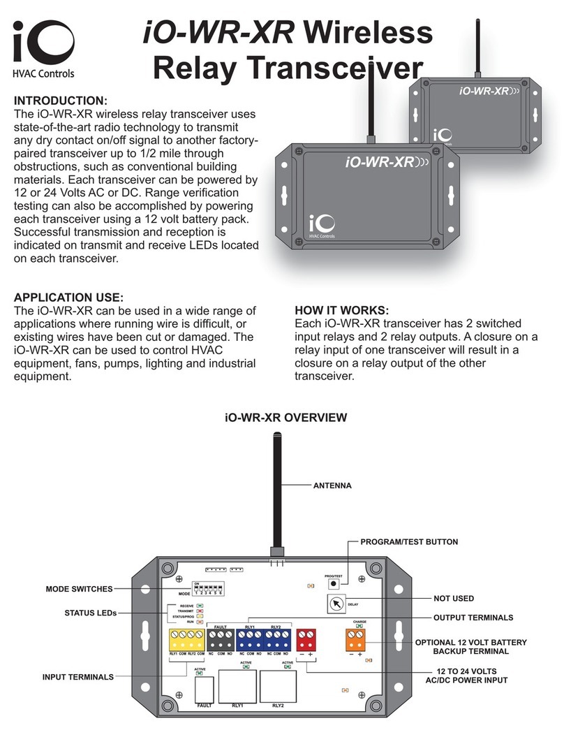
ANTENNA
INPUT TERMINALS
OUTPUT TERMINALS
12 TO 24 VOLTS
AC/DC POWER INPUT
OPTIONAL 12 VOLT BATTERY
BACKUP TERMINAL
iO-WR-XR OVERVIEW
STATUS LEDs
MODE SWITCHES
PROGRAM/TEST BUTTON
NOT USED
FAULT RLY1 RLY2
WR-XR
iO-
HVAC Controls
WR-XR
iO-
HVAC Controls

INSTALLATION:
1. Both iO-WR-XR relay transceivers are
identical and are already factory paired.
2. Each iO-WR-XR requires continuous 12 or
24 volts AC/DC power.
3. Mount each iO-WR-XR on a non-metalic
surface in a location that allows access to
wiring of device inputs and/or outputs.
4. Do not mount transceivers inside metal
enclosures as this will greatly impede the
transmission range.
5. It is recommended that 18-gauge solid (not
stranded) thermostat wire be used. Only strip
enough insulation off wires to insert into
terminals and make sure no bare wires touch
any components on the PC board. Do not
over-tighten the mounting screws.
6. Depending on the application, not all
transceiver inputs and outputs will be used.
TERMINAL DESIGNATIONS:
● ● ● ●● ● ● ●
ON
1 2 3 4 5 6
MODE
RECEIVE
TRANSMIT
STATUS/PROG
RUN
PROG/TEST
DELAY
CHARGE
ACTIVE
ACTIVE ACTIVE
FAULT RLY1 RLY2
RLY1 COM RLY2 COM NC COM NO NC COM NO NC COM NO
Relay Inputs
RLY1 COM RLY2 COM
Each iO-WR-XR has 2
switched relay inputs.
Example: A closure on RY1
will result in a closure on RY1
(NC/COM/NO) output of the
paired transceiver.
Relay Outputs
NC COM NO NC COM NO NC COM NO
FAULT RLY1 RLY2
Each iO-WR-XR has 2 relay outputs plus a
fault relay designed to open if there is a loss of
communications between the transceiver pairs
after 90 seconds.
Power Input
Power Input accepts 12 to 24 Volts
AC or DC. Always follow polarity
when DC power is used. Each
transceiver requires a minimum of 1
Amp (20VA) power supply.
Battery Input
Each transceiver can be provided with
an optional battery backup. The input
is for a 12 Volt Sealed Lead Acid
(SLA) battery only. Transceivers
provide a 12 volt trickle charge.
STATUS LEDs:
● ● ●●● ● ● ●
ON
1 2 3 4 5 6
MODE
RECEIVE
TRANSMIT
STATUS/PROG
RUN
PROG/TEST
DELAY
CHARGE
ACTIVE
ACTIVE ACTIVE
FAULT RLY1 RLY2
RLY1 COM RLY2 COM NC COM NO NC COM NO NC COM NO
1
2
3
4
5
6
FAULT RLY1 RLY2
FAULT RLY1 RLY2
7
1. RECEIVE - Flashes GREEN momentarily
when a valid radio transmission is received.
2. TRANSMIT - Flashes RED momentarily
when the transceiver transmits as a result of a
relay input change.
3. STATUS/PROG - Flashes YELLOW patterns
indicating status of the unit: pairing, error, etc.
4. RUN - Flashes ORANGE for 1 second ON
and 1 second OFF indicating the
microprocessor is running.
5. POWER LEDs - Glow solid ORANGE when
power is present for relay, logic and power
amplifier supply.
6. CHARGING - Solid GREEN when optional
battery is charging. Momentary flashing when
battery is charged and a trickle charge is
occurring.
7. ACTIVE - Solid GREEN when relay is
energized.
SWITCHES SHOWN
IN OFF POSITION

ON
1 2 3 4 5 6
MODE
DIP SWITCHES:
SWITCH 1 - Pairing mode when ON and
Normal operating mode when OFF.
SWITCH 2 through 6 - Not used.
PROG/TEST
PROGRAM/TEST BUTTON:
Used with MODE DIP SWITCH 1 to field-pair
transceivers.
Functions as a Test/Transmit button during
normal operation. When pressed, transceiver
sends a radio test packet and the RED
TRANSMIT LED will illuminate. Paired
transceiver will acknowledge the packet was
received with a radio test packet indicated by a
momentary GREEN RECEIVE LED.
FIELD-PAIRING TRANSCEIVERS:
1. Put MODE DIP SWITCH 1 in the ON
position for both transceivers.
2. Press the PROG/TEST button on either
transceiver. Observe that the STATUS/PROG
LED flashes.
3. Put MODE DIP SWITCH 1 in the OFF
position for both transceivers.
4. Press PROG/TEST on either transceiver and
observe that TRANSMIT and RECEIVE LEDs
operate normally.
Pairing procedure overwrites any previous
pairing. For example, if replacing only one
transceiver, simply follow the above
procedure with both the existing and
replacement transceiver.
COMPLIANCE:
The iO-WR-XR Wireless Transceiver has been
tested and found to comply with the limits for a
Class B digital device, pursuant to part 15 of the
FCC Rules. These limits are designed to
provide reasonable protection against harmful
interference in a residential installation. This
equipment generates, uses and can radiate
radio frequence energy, and if not installed and
used in accordance with the instructions, may
cause harmful interference to radio
communications. There is no guarantee that
interference will not occur in a particular
installation. If this equipment does cause
harmful interference to radio or television
reception, which can be determined by turning
the equipment off and on, the user is
encouraged to try to correct the interference by
one or more of the following measures.
- Reorient or relocate the receiving antenna.
- Increase the separation between the
equipment and receiver.
- Connect the equipment into an outlet or circuit
different from that to which the receiver is
connected.
SPECIFICATIONS:
Dimensions:
Power Input:
Channels:
Contact Rating:
Addresses:
Frequency:
Range:
Operating Temp:
Operating RH:
3.75” H x 5.25” W x 2” D
12 or 24 Volts AC or DC
2 Send, 2 Receive
10A per channel
Factory-paired
Multiple units can be used
in same location
902-928 MHz
1/2 mile line of sight
-40°F to 185°F
0 to 95% (non-condensing)
OFF

TYPICAL WIRING EXAMPLES
RLY1 COM RLY2 COM NC COM NO NC COM NO NC COM NO
TRANSCEIVER 2
Indianapolis, IN 46237
www.iohvaccontrols.com
For Technical Support: 866-225-5032
ONE WAY TRANSMISSION (VOLTAGE OUTPUT)
RLY1 COM RLY2 COM NC COM NO NC COM NO NC COM NO
TRANSCEIVER 1
UNIT 1
UNIT 2
RLY1 COM RLY2 COM NC COM NO NC COM NO NC COM NO
TRANSCEIVER 1
UNIT 1
UNIT 2
RLY1 COM RLY2 COM NC COM NO NC COM NO NC COM NO
TRANSCEIVER 2
TWO WAY TRANSMISSION (DRY CONTACT OUTPUT
OUTPUT 1
DRY CONTACTS
AUX 1
AUX 1 OUTPUT
DRY CONTACTS
TWO WAY TRANSMISSION (VOLTAGE OUTPUT)
RLY1 COM RLY2 COM NC COM NO NC COM NO NC COM NO
TRANSCEIVER 1
UNIT 1
UNIT 2
24V LINE
TRANSFORMER
LOAD #1
LOAD #2
RLY1 COM RLY2 COM NC COM NO NC COM NO NC COM NO
TRANSCEIVER 2
24V LINE
LOAD #1
LOAD #2
RLY1 COM RLY2 COM NC COM NO NC COM NO NC COM NO
TRANSCEIVER 2
24V LINE
TRANSFORMER
LOAD #1
LOAD #2
RLY1 COM RLY2 COM NC COM NO NC COM NO NC COM NO
TRANSCEIVER 2
24V LINE
LOAD #1
LOAD #2
AUX 1
LINE
TRANSFORMER
24V LINE
TRANSFORMER
24V LINE
TRANSFORMER
24V LINE
TRANSFORMER
24V LINE
OUTPUT 2
DRY CONTACTS

RLY1 COM RLY2 COM NC COM NO NC COM NO NC COM NO
INDOOR UNIT TRANSCEIVER
C
R
Y
O
G
W
C
R
Y
O
G
W
24V
COIL
NO C NC
24V
COIL
NO C NC
RLY1 COM RLY2 COM NC COM NO NC COM NO NC COM NO
OUTDOOR UNIT TRANSCEIVER
24V
COIL
NO C NC
24V
COM
HOT
LINE
C
R
Y
O
W
COMPRESSOR
REVERSING VALVE
DEFROST
SPDT
RELAY
ENERGIZED
WHEN UNIT
GOES INTO
DEFROST
SPDT
RELAY
SPDT
RELAY
iO-WR-XR WIRELESS RELAY USED FOR SINGLE COMPRESSOR
HEAT PUMP WITH DEFROST SIGNAL
Indianapolis, IN 46237
www.iohvaccontrols.com
For Technical Support: 866-225-5032
TRANSFORMER
COM
HOT
FAN
AUXILIARY HEAT

RLY1 COM RLY2 COM NC COM NO NC COM NO NC COM NO
INDOOR UNIT TRANSCEIVER
C
R
Y1
Y2
G
W1
W2
C
R
Y1
Y2
G
W1
W2
24V
COIL
NO C NC
24V
COIL
NO C NC
RLY1 COM RLY2 COM NC COM NO NC COM NO NC COM NO
OUTDOOR UNIT TRANSCEIVER
24V
COM
HOT
LINE
C
R
Y1
Y2
COMPRESSOR 1
SPDT
RELAY
SPDT
RELAY
iO-WR-XR WIRELESS RELAY USED FOR TWO STAGE
CONDENSING UNIT
Indianapolis, IN 46237
www.iohvaccontrols.com
For Technical Support: 866-225-5032
TRANSFORMER
COMPRESSOR 2
iO-06-1315-060820
COM
HOT
FAN
HEAT 1
HEAT 2
Table of contents
Other iO HVAC Controls Transceiver manuals


