ionGen GTX12V315A-E2107-CS200 Assembly instructions

LITHIONICS BATTERY, CLEARWATER, FL 33765 USA | PH: 727.726.4204 | FAX: 727.797.8046 | WEB: LITHIONICSBATTERY.comRevision 05
Installer's Guide
GTX12V315A-E2107-CS200 INSTALLATION KIT
VICTRON MULTIPLUS II 3000 WATT (SINGLE BATTERY)

S A F E T Y I N F O R M A T I O N . . . . . . . . . . . . . . . . . . . . . . . . . . . . . . . . . . . . . . . . . . . . 1
I N T R O D U C T I O N . . . . . . . . . . . . . . . . . . . . . . . . . . . . . . . . . . . . . . . . . . . . . . . . . . . . . . .
W I R I N G D I A G R A M S . . . . . . . . . . . . . . . . . . . . . . . . . . . . . . . . . . . . . . . . . . . . . . . . . . 3
MAIN DIAGRAM.......................................................
INVERTER DIAGRAM...............................................
POWER FLOW DIAGRAMS.....................................
STERLING DIAGRAM..............................................
SOLAR DIAGRAM....................................................
BATTERY/IONGAGE DIAGRAM..............................
PARTS LIST.............................................................
BATTERY INSTALLATION.......................................
EQUIPMENT MANUALS..........................................
Table of Contents
LITHIONICS BATTERY, CLEARWATER, FL 33765 USA | PH: 727.726.4204 | FAX: 727.797.8046 | WEB: LITHIONICSBATTERY.com
2
4
7
13
15
17
19
20
25
10

Safety Information
1
!
LITHIONICS BATTERY, CLEARWATER, FL 33765 USA | PH: 727.726.4204 | FAX: 727.797.8046 | WEB: LITHIONICSBATTERY.com
Links to the installation manuals relevant to this kit are listed at the back of this manual.
This manual is intended to be used by qualified installers. Although it is quite detailed, it is meant only as an overall guide
to the installation and not to replace the manuals supplied by the relevant equipment manufacturers.
All electrical work should be performed in accordance with local and national electrical codes. Assume that voltage is
present at the battery terminals; use insulated tools and gloves while working on the system. Always turn off equipment
connected to the battery in addition to turning OFF the Power switch on the battery to isolate it from other electrical
circuits before performing any repairs or maintenance on the system.
Always use proper wire sizes to connect the system to inverters, chargers or other equipment. Always use crimped
connections to connect to the battery terminals.
Read and follow the inverter, charger or other equipment manufacturer’s safety precautions prior to connecting the battery
to that equipment. Always use charging equipment compatible with Lithium Iron Phosphate battery chemistry.

2
LITHIONICS BATTERY, CLEARWATER, FL 33765 USA | PH: 727.726.4204 | FAX: 727.797.8046 | WEB: LITHIONICSBATTERY.com
Introduction
The Lithionics GTX12V315A-E2107-CS200 Victron kit is
based on a GTX12V315A-E2107-CS200 battery (315
amp hours) and a Victron MultiPlus II 3000-watt inverter.
This combination is capable of providing enough power to
run your AC loads for extended periods of time. The inverter
features true sine wave grid quality power, adaptive
charging, Power Assist, and many system integration
features.

Main Diagram
Inverter Diagram
Power Flow Diagrams
Sterling Diagram
Solar Diagram
Battery/IonGage Diagram
Wiring Diagrams
LITHIONICS BATTERY, CLEARWATER, FL 33765 USA | PH: 727.726.4204 | FAX: 727.797.8046 | WEB: LITHIONICSBATTERY.com 3

Main Diagram
LITHIONICS BATTERY, CLEARWATER, FL 33765 USA | PH: 727.726.4204 | FAX: 727.797.8046 | WEB: LITHIONICSBATTERY.com 4
The main diagram depicts the general layout of the system. The 2/0 AWG battery positive cable is connected to the
main positive distribution bus via a 300A post-mounted fuse and an isolation switch.
The inverter is connected to the positive distribution bus via a 250A class T fuse and an isolation switch. The class T
fuse block should be mounted as close as possible to the positive distribution bus. The inverter switch is required for
inverter isolation and inrush management when first turning on the system. The chassis DC grounding cable (green)
should be sized not less than one size smaller than the DC positive conductor and have a capacity such that the DC
positive fuse has an amperage rating not greater than 135% of the current rating of this ground wire.
If the positive cable supplying the inverter shorts to ground internally, then the chassis ground cable needs to be able
to carry enough current to blow the inverter fuse without melting and possibly causing a fire.

Main Diagram
LITHIONICS BATTERY, CLEARWATER, FL 33765 USA | PH: 727.726.4204 | FAX: 727.797.8046 | WEB: LITHIONICSBATTERY.com 5
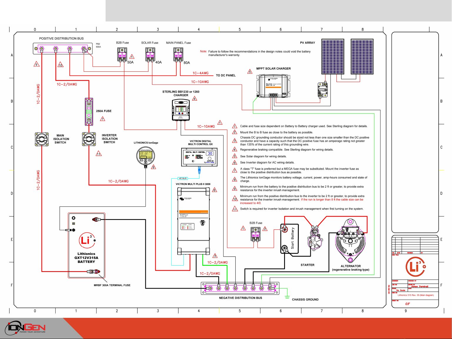
The inverter is controlled by the Digital Multi Control Panel. The front mounted switch is used to turn the system on, off or to charger only
operation. The shore current limit is set by the control knob. Turning the knob to the right or left sets the desired value. The current limit is shown
on the 7-segment display.
The Lithionics IonGage monitors battery voltage, current, power, amp-hours consumed and state of charge.
The Victron Smart Solar MPPT charger is connected to the positive distribution bus via a 40A Maxi fuse. The PV solar array is connected to
the MPPT charger via a circuit breaker. The specified circuit breaker is only rated at 48VDC; if your PV solar array has an open circuit voltage
that is higher, then another circuit breaker with a higher voltage rating must be substituted. The fuse and wire sizes are based on the Victron
Smart Solar MPPT 100/30 charge controller, if a larger controller is used then the fuse and wire sizes should be increased as required.
The Sterling Battery to Battery charger is connected to the positive distribution bus via a 50A Maxi fuse (80A for the Sterling BB1260 charger).
It also has a fuse at the starter battery, this fuse must be installed as close to the battery as possible.
Wiring note:
A total DC power circuit resistance between a single Lithionics battery and a 3000W inverter can be as low as 5 mOhm (0.005 Ohm), when
using short wires to connect the battery to the inverter. With a typical battery voltage of 13.5V, this can result in an inrush peak current of 2,700
Amps (!!!) from the battery to the inverter capacitors. This surge only lasts around 1 millisecond but could be enough to damage the Battery
Management System (BMS) or even damage the inverter. The minimum required wire size and length stated in the wiring diagram are provided
to ensure minimum circuit resistance of at least 5.6 mOhm to reduce the inrush under 2,400A. For more information refer to Lithionics Support
page, FAQ Section at this link https://lithionicsbattery.com/support/

MAIN DIAGRAM
LITHIONICS BATTERY, CLEARWATER, FL 33765 USA | PH: 727.726.4204 | FAX: 727.797.8046 | WEB: LITHIONICSBATTERY.com 6

Inverter Diagram
LITHIONICS BATTERY, CLEARWATER, FL 33765 USA | PH: 727.726.4204 | FAX: 727.797.8046 | WEB: LITHIONICSBATTERY.com 7
A warning label should be installed at the main AC panel to indicate that there is an inverter in the system.
The inverter diagram depicts the Victron Multiplus II configured with a 120/240
VAC split/phase shore power input. The MultiPlus II can also be configured for
single/phase 120VAC input. When an AC source is available, the MultiPlus II will
feed through the AC to its output. The output will therefore mirror the AC input.
When the MultiPlus II is in inverter mode the output is 120V single phase only. In
inverter mode, the MultiPlus II connects both output lines (L1 and L2) together to
provide 120VAC to loads on either line.
Any 240V loads will only be supplied when the MultiPlus II is supplied by a splitphase
AC source. This prevents heavy loads such as water heaters or 240V air conditioners
from discharging the battery.
The AC input must be protected by a magnetic circuit breaker rated at 50A or less,
and the cable cross-section must be sized accordingly. Make all connections using
proper crimp-on connectors (do not use twist on connectors).

Inverter Diagram
LITHIONICS BATTERY, CLEARWATER, FL 33765 USA | PH: 727.726.4204 | FAX: 727.797.8046 | WEB: LITHIONICSBATTERY.com 8
The MultiPlus II has two AC outputs AC-1 and AC-2.
AC-1
The MultiPlus II provides power to the AC-1 output (120V only) when the shore power is disconnected. With its
PowerAssist feature the MultiPlus II can add up to 3kVA to the AC-1 output during periods of peak power requirement.
Together with a maximum input current of 50A this means that the output can supply up to 75 A. An earth leakage circuit
breaker rated to support the expected load must be included in series with the output, and cable cross-section must be
sized accordingly. The maximum rating of the circuit breaker is 75A.
AC-2
The auxiliary (AC-2) output is live only when AC is available on the input of the MultiPlus II. Heavy loads that would
discharge the battery can be connected to this output. The maximum rating of the circuit breaker is 35A.
The inverter is provided with a ground relay that automatically connects the neutral output to the chassis ground if no
external AC supply is available. In an RV installation, the inverter chassis must be connected to the vehicle chassis
ground (via the negative distribution bus). The chassis grounding conductor must be sized not less than one size smaller
than the DC positive conductor and have a capacity such that the DC positive fuse has an amperage rating not greater
than 135% of the current rating of this grounding wire.
For a graphical view of the power flow please see the power flow diagrams included in this manual.

I N V E R T E R D I A G R A M
LITHIONICS BATTERY, CLEARWATER, FL 33765 USA | PH: 727.726.4204 | FAX: 727.797.8046 | WEB: LITHIONICSBATTERY.com 9

P O W E R F L O W D I A G R A M 1
LITHIONICS BATTERY, CLEARWATER, FL 33765 USA | PH: 727.726.4204 | FAX: 727.797.8046 | WEB: LITHIONICSBATTERY.com 10

P O W E R F L O W D I A G R A M 2
LITHIONICS BATTERY, CLEARWATER, FL 33765 USA | PH: 727.726.4204 | FAX: 727.797.8046 | WEB: LITHIONICSBATTERY.com 11

P O W E R F L O W D I A G R A M 3
LITHIONICS BATTERY, CLEARWATER, FL 33765 USA | PH: 727.726.4204 | FAX: 727.797.8046 | WEB: LITHIONICSBATTERY.com 12

Sterling Diagram
LITHIONICS BATTERY, CLEARWATER, FL 33765 USA | PH: 727.726.4204 | FAX: 727.797.8046 | WEB: LITHIONICSBATTERY.com 13
Sterling Power Battery to Battery Charger 12V input to
12V output 30amps
Sterling Power Battery to Battery Charger 12V input to
12V output up to 60amps.
The Sterling Battery to Battery charger charges the house battery via the vehicle’s alternator. This system uses either the Sterling
BB1230 charger (Mercedes recommendation), or the BB1260 charger depending on the size of the alternator. The charger should be
programmed to charge the battery using a Lithium battery profile. The charger can also be configured to work with vehicles using
regenerative braking.

S T E R L I N G D I A G R A M
LITHIONICS BATTERY, CLEARWATER, FL 33765 USA | PH: 727.726.4204 | FAX: 727.797.8046 | WEB: LITHIONICSBATTERY.com 14

Solar Diagram
LITHIONICS BATTERY, CLEARWATER, FL 33765 USA | PH: 727.726.4204 | FAX: 727.797.8046 | WEB: LITHIONICSBATTERY.com 15
The Victron Smart Solar MPPT solar charge controller uses maximum power point
tracking that optimizes the match between the solar array and the battery bank. It
converts the higher voltage DC output from the solar panels down to the lower
voltage needed to charge the batteries. The PV solar array is connected to the MPPT
charger with a circuit breaker (not supplied). The specified circuit breaker is only
rated at 48VDC; if your PV solar array has an open circuit voltage that is higher,
then another circuit breaker with a higher voltage rating must be substituted.
The charger is connected to the positive distribution bus via a 40A fuse. The fuse
and wire sizes are based on the Victron MPPT 100/30 charge controller, if a larger
controller is used then the fuse and wire sizes should be increased as required.
Using the VictronConnect App on your smartphone you can connect via blue tooth
and remotely control and monitor the Smart Solar MPPT charger.

S O L A R D I A G R A M
LITHIONICS BATTERY, CLEARWATER, FL 33765 USA | PH: 727.726.4204 | FAX: 727.797.8046 | WEB: LITHIONICSBATTERY.com 16

Battery/IonGage Diagram
LITHIONICS BATTERY, CLEARWATER, FL 33765 USA | PH: 727.726.4204 | FAX: 727.797.8046 | WEB: LITHIONICSBATTERY.com 17
The Advanced Series BMS includes an integrated SOC Gauge, designed to track battery state of charge (percent of
usable energy left in the battery) as well as other useful data parameters. Tracking state of charge is accomplished by a
Coulomb counter, based on an internal, high sensitivity hall-effect sensor. The SOC Gauge data will only be correct if the
configuration parameters are set correctly, which are pre-set initially by Lithionics Battery, but are user adjustable with
supporting hardware. The SOC Gauge will also track and display live amperage (A), live wattage (W), battery voltage (V),
temperature (F/C), amp hours (Ah), watt hours (Wh), time remaining (d/h), etc. The meter will be most accurate if the
battery is fully charged on a regular basis. If the battery is always partially charged, then the SOC meter reading may drift
in the long term and will become less accurate. When the most accurate measurements are required it is recommended
to perform a full charge at least weekly.

BATTE RY/I ONGAGE DIAGRAM
LITHIONICS BATTERY, CLEARWATER, FL 33765 USA | PH: 727.726.4204 | FAX: 727.797.8046 | WEB: LITHIONICSBATTERY.com 18
Table of contents
Popular Inverter manuals by other brands

Sealey
Sealey PP35.V2 instructions

Sundaya
Sundaya Apple user manual

Wavetek
Wavetek Meterman FG2C Operator's manual

Generac Power Systems
Generac Power Systems 004270-2 Installation and owner's manual

AIMS Power
AIMS Power PWRI100012120S instruction manual

MAGIRA
MAGIRA ASKIS PSI-6 Assembly and operating instructions