© ioSelect Inc. CONFIDENTIAL 2
ioSelect
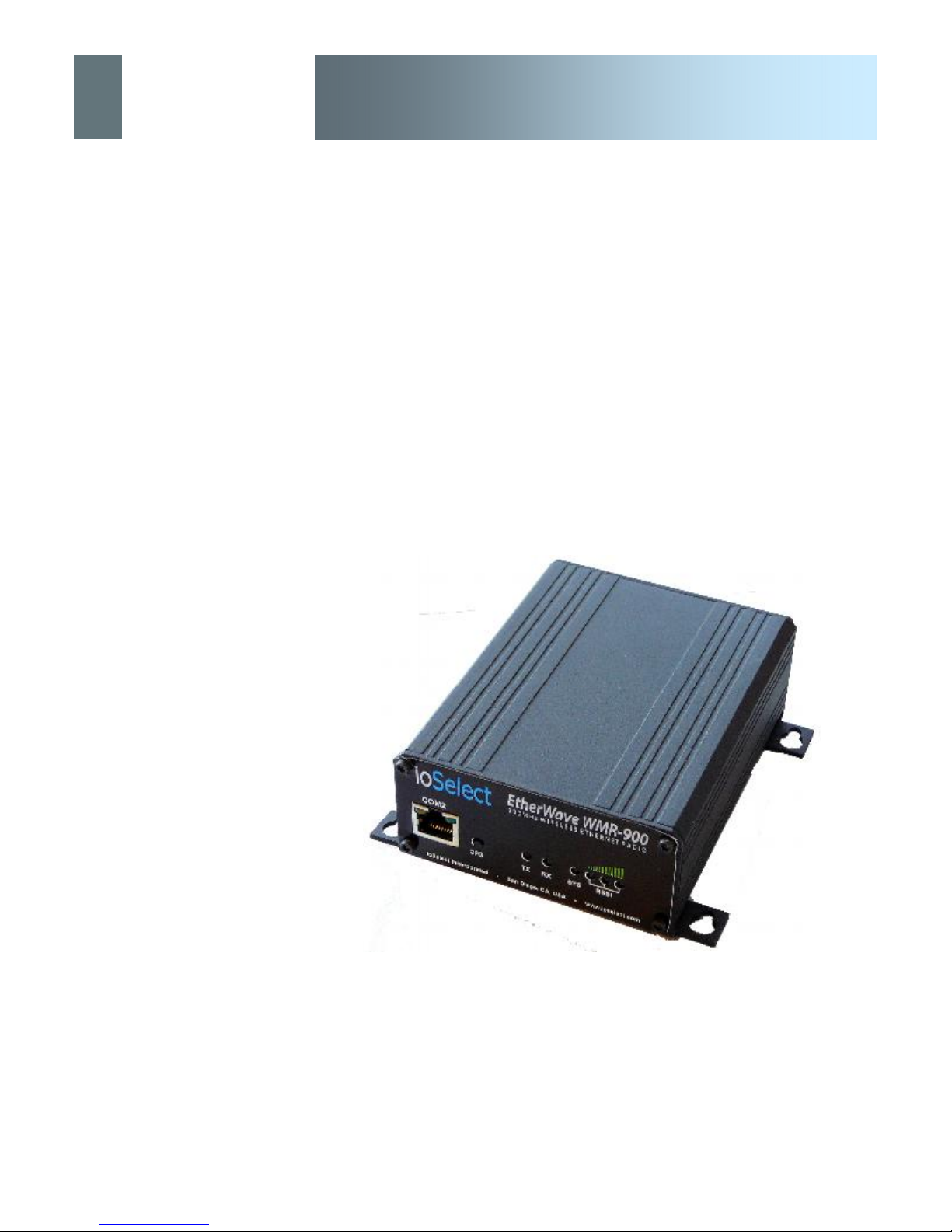
EtherWave - WMR
Important User Information
Warranty
IoSelect Inc. warrants that each product will be free of defects in material and workmanship for a period of
one (1) year for its products. The warranty commences on the date the product is shipped by IoSelect Inc.
IoSelect Inc.’s sole liability and responsibility under this warranty is to repair or replace any product which is
returned to it by the Buyer and which IoSelect Inc. determines does not conform to the warranty. Product re-
turned to IoSelect Inc. for warranty service will be shipped to IoSelect Inc. at Buyer’s expense and will be re-
turned to Buyer at IoSelect Inc.’s expense. In no event shall IoSelect Inc. be responsible under this warranty
for any defect which is caused by negligence, misuse or mistreatment of a product or for any unit which has
been altered or modified in any way. The warranty of replacement shall terminate with the warranty of the
product.
Warranty Disclaims
IoSelect Inc. makes no warranties of any nature of kind, expressed or implied, with respect to the hardware,
software, and/or products and hereby disclaims any and all such warranties, including but not limited to war-
ranty of non-infringement, implied warranties of merchantability for a particular purpose, any interruption or
loss of the hardware, software, and/or product, any delay in providing the hardware, software, and/or product
or correcting any defect in the hardware, software, and/or product, or any other warranty. The Purchaser
represents and warrants that IoSelect Inc. has not made any such warranties to the Purchaser or its agents
IOSELECT INC. EXPRESS WARRANTY TO BUYER CONSTITUTES IOSELECT INC. SOLE LIABILITY AND THE
BUYER’S SOLE REMEDIES. EXCEPT AS THUS PROVIDED, IOSELECT INC. DISCLAIMS ALL WARRANTIES, EX-
PRESS OR IMPLIED, INCLUDING ANY WARRANTY OF MERCHANTABILITY OR FITNESS FOR A PARTICULAR
PROMISE.
IOSELECT INC. PRODUCTS ARE NOT DESIGNED OR INTENDED TO BE USED IN ANY LIFE SUP-
PORT RELATED DEVICE OR SYSTEM RELATED FUNCTIONS NOR AS PART OF ANY OTHER
CRITICAL SYSTEM AND ARE GRANTED NO FUNCTIONAL WARRANTY.
Indemnification
The Purchaser shall indemnify IoSelect Inc. and its respective directors, officers, employees, successors and
assigns including any subsidiaries, related corporations, or affiliates, shall be released and discharged from
any and all manner of action, causes of action, liability, losses, damages, suits, dues, sums of money, ex-
penses (including legal fees), general damages, special damages, including without limitation, claims for per-
sonal injuries, death or property damage related to the products sold hereunder, costs and demands of every
and any kind and nature whatsoever at law.
IN NO EVENT WILL IOSELECT INC. BE LIABLE FOR ANY INDIRECT, SPECIAL, CONSEQUENTIAL, INCIDENTAL,
BUSINESS INTERRUPTION, CATASTROPHIC, PUNITIVE OR OTHER DAMAGES WHICH MAY BE CLAIMED TO
ARISE IN CONNECTION WITH THE HARDWARE, REGARDLESS OF THE LEGAL THEORY BEHIND SUCH CLAIMS,
WHETHER IN TORT, CONTRACT OR UNDER ANY APPLICABLE STATUTORY OR REGULATORY LAWS, RULES,
REGULATIONS, EXECUTIVE OR ADMINISTRATIVE ORDERS OR DECLARATIONS OR OTHERWISE, EVEN IF IOSE-
LECT INC. HAS BEEN ADVISED OR OTHERWISE HAS KNOWLEDGE OF THE POSSIBILITY OF SUCH DAMAGES
AND TAKES NO ACTION TO PREVENT OR MINIMIZE SUCH DAMAGES. IN THE EVENT THAT REGARDLESS OF
THE WARRANTY DISCLAIMERS AND HOLD HARMLESS PROVISIONS INCLUDED ABOVE IOSELECT INC. IS SOME-
HOW HELD LIABLE OR RESPONSIBLE FOR ANY DAMAGE OR INJURY, IOSELECT INC.'S LIABILITY FOR ANYDAM-
AGES SHALL NOT EXCEED THE PROFIT REALIZED BY IOSELECT INC. ON THE SALE OR PROVISION OF THE
HARDWARE TO THE CUSTOMER.
Proprietary Rights
The Buyer hereby acknowledges that IoSelect Inc. has a proprietary interest and intellectual property rights in
the Hardware, Software and/or Products. The Purchaser shall not (i) remove any copyright, trade secret,
trademark or other evidence of IoSelect Inc.’s ownership or proprietary interest or confidentiality other pro-
prietary notices contained on, or in, the Hardware, Software or Products, (ii) reproduce or modify any Hard-
ware, Software or Products or make any copies thereof, (iii) reverse assemble, reverse engineer or decompile
any Software or copy thereof in whole or in part, (iv) sell, transfer or otherwise make available to others the
Hardware, Software, or Products or documentation thereof or any copy thereof, except in accordance with this
Agreement.
ioSelect