San Telequip SC10MK2 User manual

San Telequip (P) Ltd.,
504,505 Deron Heights, Baner Road
Pune 411 045, India
Phone : +91-20-27293455, 9764027070, 8390069393 Connecting. Converting. Leading!
email : [email protected]
User Manual 2-Port TCP to RTU Gateway, Model SC10MK2 485 IOT 502
Table of Contents
Introduction ______________________________________________________________________________ 1
Product Specifications______________________________________________________________________ 2
Product Panel Views _______________________________________________________________________ 3
Wiring Architecture ________________________________________________________________________ 5
Configuration_____________________________________________________________________________ 6
IP Search Utility Setup ___________________________________________________________________ 6
Web Browser Configuration _______________________________________________________________ 9
1. System Setup___________________________________________________________________ 9
2. Network ______________________________________________________________________ 11
3. Serial ________________________________________________________________________ 13
3.9 Service: Modbus TCP Gateway - Select both Serial1 and Serial2 at the same time against a
specified TCP socket port commonly. ____________________________________________________ 14
4. Access IP Control_______________________________________________________________ 15
5. Save & Restart_________________________________________________________________ 16
6. Backup Settings ________________________________________________________________ 16
Introduction
SC10MK2 485 IOT 502 Modbus TCP to RTU Gateway provides easy way of connecting Modbus RTU devices to
Wireless and Ethernet LAN. The wireless supports 802.11 b/g/n in AP/Station mode with WEP/WPA/WPA2
encryption for data transmission security. The Ethernet support 10/100 Mbps auto-detecting communication
speeds. This Gateway is designed to operate 2 Serial ports (RS-232/RS-422/485 Auto detect) over Wireless and
Ethernet network. It allows users to integrate Modbus/RTU and Modbus Serial devices to the TCP/IP network
with 8 TCP Masters simultaneously and 32 requests simultaneous per TCP Master.
SC10MK2 485 IoT 502 embedded with MT7688AN MIPS chipset makes it become the ideal device for
transmitting the data from your RS-232 or RS-422/485 Serial interface devices, such as PLCs, Meters and
Sensors to an IP-based Wi-Fi and Ethernet LAN. It is a high performance design composed with carefully
selecting qualified components from reliable and certified sources. This operation manual will guide you to
configure functions step by step.

San Telequip (P) Ltd.,
504,505 Deron Heights, Baner Road
Pune 411 045, India
Phone : +91-20-27293455, 9764027070, 8390069393 Connecting. Converting. Leading!
email : [email protected]
Product Specifications
System
CPU: MT7688AN MIPS CPU, 580 MHz
RAM: 128M Bytes DDR2 RAM
ROM: 32M Bytes Flash ROM
OS : OpenWrt Linux OS
TCP to RTU support 8 simultaneous TCP Master, 32 simultaneous requests per Master.
RTU to TCP is not available
Ethernet
Port Type: RJ-45 Connector
Speed: 10 /100 M bps ( Auto Detecting )
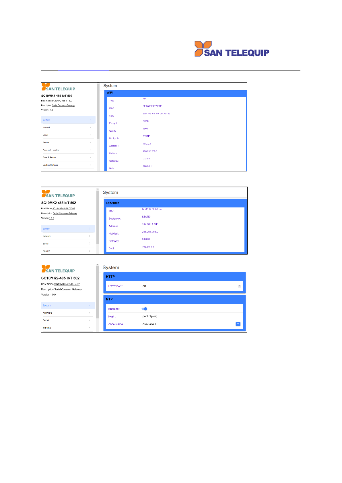
Protocol: ARP, IP, ICMP, UDP, TCP, HTTP, DHCP, NTP
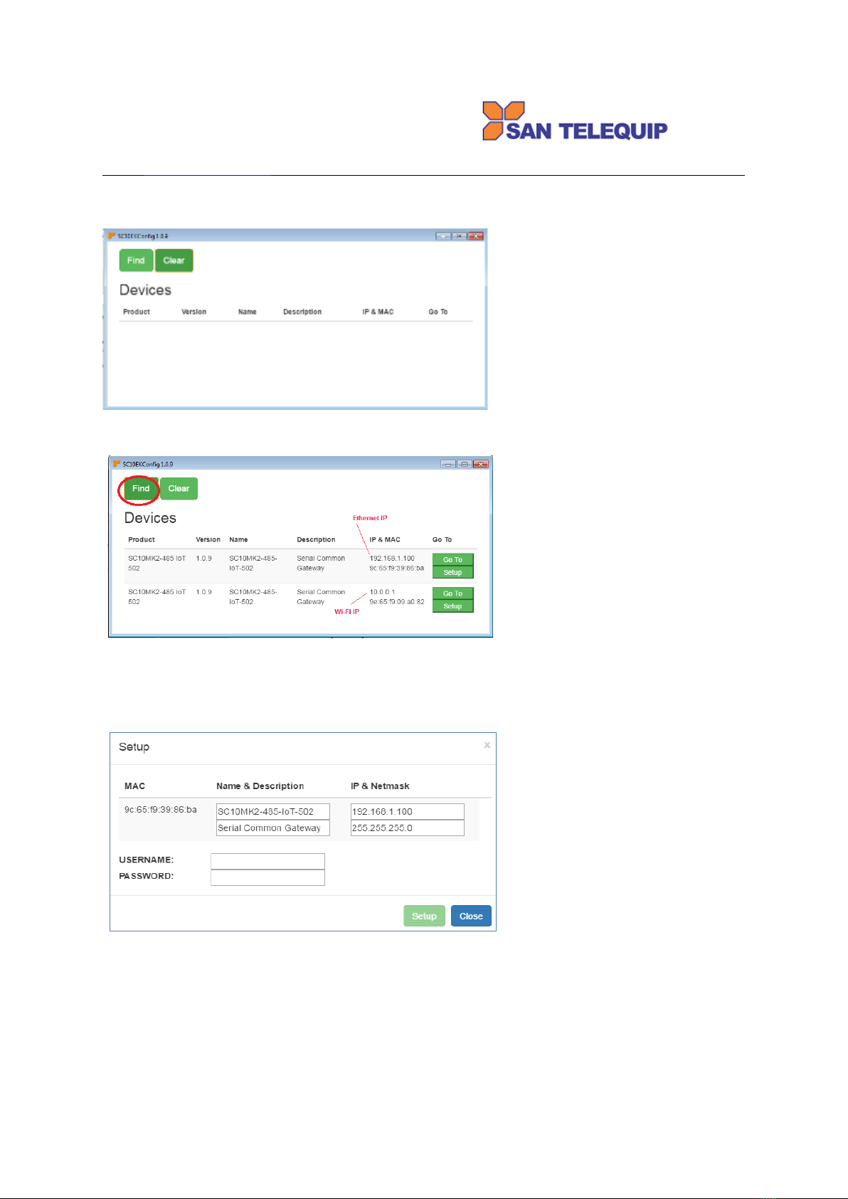
Setup: HTTP Browser Setup (IE, Chrome, Firefox)
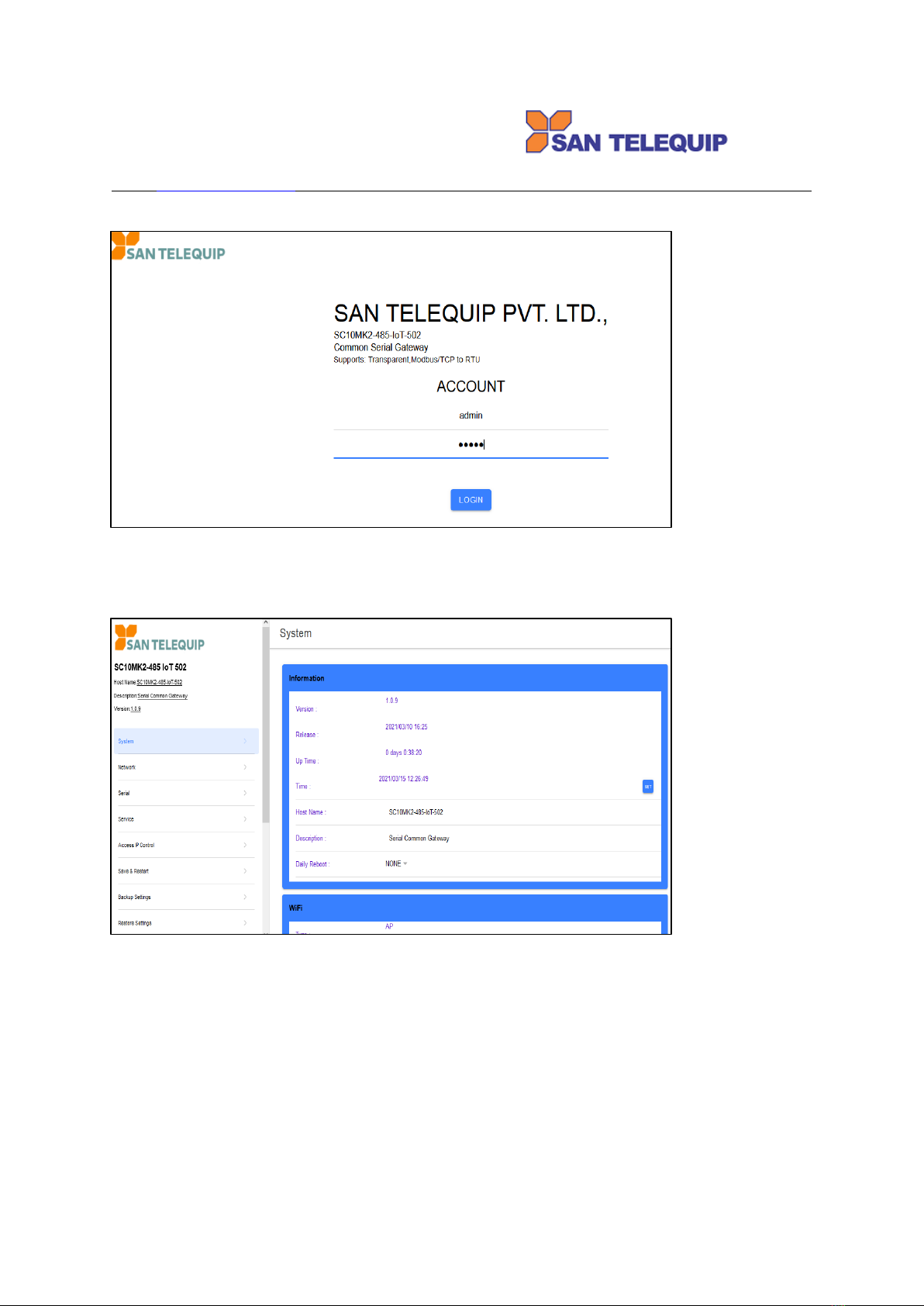
Security: Setup Password
Protection: Built-in 1.5KV Magnetic Isolation
WiFi port (option)
Support AP / Station
Standard : 2.4G IEEE 802.11b/g/n
Data Rate : 11/54/72.2 Mbps @ 20Mhz Band Width
Modulation : DSSS; OFDM
Frequency : 2.4GHz
Tx Power 11b : Max. 22dBm
Tx Power 11g/n : Max. 19dBm
Rx Sensitivity : -76dBm @ 54Mbps; -89.5dBm @ 11Mbps
Tx Rate : Max. 54Mbps with auto fallback
Tx Distance : Up to 100m
Security : WEP 64-bit / 128-bit data encryption, WPA / WPA2 personal
Antenna : 2 dBi ; RP-SMA connector
Network Mode: Infrastructure; Soft AP (for Setup)
Setup : HTTP Browser Setup (IE, Chrome, Firefox)
Security : Login Password
Serial Ports *2
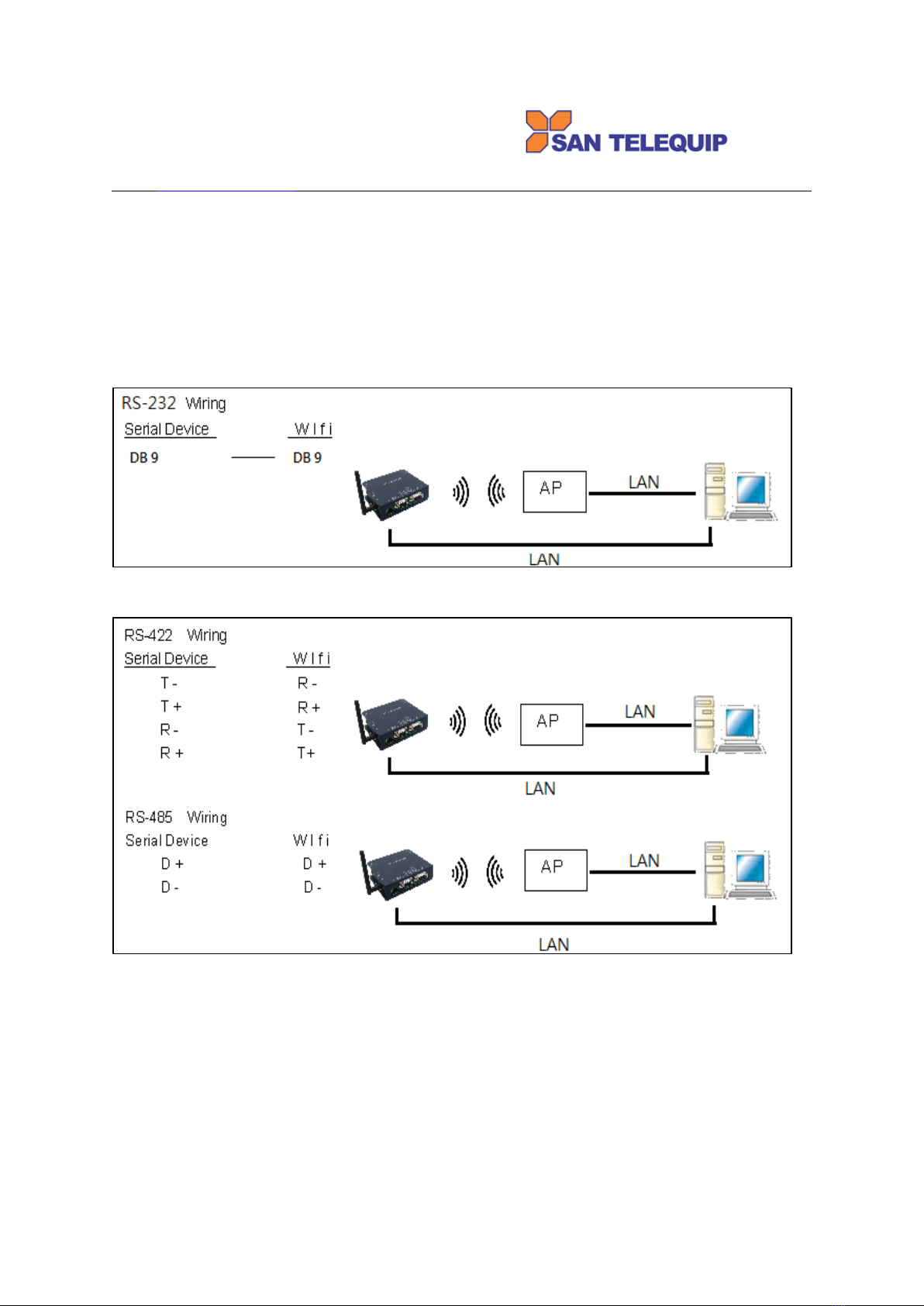
Port : RS-232/422/485 * 2 Ports ( RS-232 with RX/TX/GND only )
Port : RS-422 / 485 ( Surge Protect )
Speed : 300 bps ~ 921.6 K bps
Parity : None , Odd , Even , Mark , Space
Data Bit : 5 , 6 , 7 , 8
Stop Bit : 1 , 2
RS-232 Pins : Rx , Tx , GND
RS-422 : Rx+ , Rx- , Tx+ , Tx- ( Surge Protect )
RS-485 : Data+ , Data- ( Surge Protect )
15KV ESD for all signals
Power
DC 9~24 V, 1000mA@12V
support DC Jack & Terminal Input
Mechanical and Environment
Operating Temperature : -20⁰C to 70⁰C
Storage Temperature : -25⁰C to 80⁰C
Dimensions : 120 * 110 * 30 mm ( W * D * H )
Weight : 460 ± 5gm
Housing: metal.
Other Features (**not this model, for programming purpose)
**Digital Input / Output : GPIO * 8 Pins
**2C Interface * 1 port
**SD Interface : micro SD card ( for 16G storage )
**USB ( Host * 1 port ) : for Memory Storage, CAMERA

San Telequip (P) Ltd.,
504,505 Deron Heights, Baner Road
Pune 411 045, India
Phone : +91-20-27293455, 9764027070, 8390069393 Connecting. Converting. Leading!
email : [email protected]
**Buzzer
Led Lamp : SYS, PWR, PoE(option), WiFi, RX, TX, LAN
RTC : Real Time Clock
Watch Dog Function
Software : TCP, Modbus TCP Master to Modbus RTU Slave
Product Panel Views
Antenna Connector
The connector for antenna is a standard reverse SMA jack. Simply connect it to a 2.0dBi dipole antenna
(Standard Rubber Duck) and it is 50 Ohms impedance and can support 2.4GHz frequency.
Ethernet Port
The connector for network is the usual RJ45. Simply connect it to your network switch or Hub. When the
connection is made, the green color LED of Ethernet port will light on. When data traffic (Rx/Tx) occurs on the
network, yellow color LED will blink during data transferring.
Serial Port of RS-232/RS-422/RS-485
Connect the serial data cable between the SC10MK2 converter and the Serial interface device. Follow the web
page parameter setup procedures to configure the converter.

San Telequip (P) Ltd.,
504,505 Deron Heights, Baner Road
Pune 411 045, India
Phone : +91-20-27293455, 9764027070, 8390069393 Connecting. Converting. Leading!
email : [email protected]
DC-IN Power Outlet
The Serial to Ethernet+WiFi Converter is powered by a single 12V DC (Inner positive, outer negative) power
supply and 1A Current. Connect the power adaptor to the AC power socket and put the DC Jack plug into the
outlet of device. The “SYS” green color LED will be ON when power is properly supplied. Terminal Block 2 wires
power supply is an option.
DC Power outlet
Reset Button (WIFI)
If any chance you forgot the login password, or have incorrect settings making converter inoperable. When the
power is on and the “SYS” LED light on, use a point tip to press this button and hold it and wait for more than 25
seconds. All the parameters will be reset to the factory default.
LED Indicators
PWR (Green) : After power on, this LED is always ON.
SYS (Green) : LED is ON after power on, and then start blinking per second a after system running.
POE (Red) : for PoE (Power on Ethernet) indication if device with this function.
WIFI (Red) : LED is ON after power on, then off a while. It starts blinking after Wi-Fi module is ON.
TX / RX (Red / Green) :Data sending or receiving indicator. When data sent out to the network or receiving
from the network, the LED will be blinking.
Antenna Connector
The connector for antenna is a standard reverse SMA jack. Simply connect it to a 2.0dBi dipole antenna
(Standard Rubber Duck). It is 50 Ohms impedance and can support 2.4GHz frequency.
Ethernet Port
The connector for network is the usual RJ45. Simply connect it to your network switch or Hub. When the
connection is made, the green color LED of Ethernet port will blink. When data traffic (Rx/Tx) occurs on the
network, yellow color LED will blink during data transferring.

San Telequip (P) Ltd.,
504,505 Deron Heights, Baner Road
Pune 411 045, India
Phone : +91-20-27293455, 9764027070, 8390069393 Connecting. Converting. Leading!
email : [email protected]
DC-IN Power Outlet
The Device is powered by a 12V DC (Inner positive, outer negative), 1.0A power supply. Plugging the power
adaptor to the AC power socket and put the DC Jack plug into the outlet of the Device. The “SYS” green color
LED will be ON when power is properly supplied. Terminal Block 2 wires power supply is an option.
Serial Port of RS-232/RS-422/RS-485
Connect the Serial data cable between the device and the Serial interface device. Follow the procedure of web
page configuration to set up parameters.
Wiring Architecture
1. RS-232
2. RS-422/RS-485
When you finish the steps mentioned above and the LED indicators are as shown, the Gateway is installed
correctly. You can check the Software Setup CD to find Utility to setup the IP Address. To proceed with the
parameters setup, please use a web browser (IE or Chrome) to continue the settings.

San Telequip (P) Ltd.,
504,505 Deron Heights, Baner Road
Pune 411 045, India
Phone : +91-20-27293455, 9764027070, 8390069393 Connecting. Converting. Leading!
email : [email protected]
Configuration
When setting up your Gateway for the first time, the first thing you should do is to configure the IP address.
The following topics are covered in this chapter:
IP Search Utility Setup
Web Browser Configuration
IP Search Utility Setup
1. Download “SC10MK2-485 IOT utility” from Web site to your host computer.
2. “SC10MK2-485 IOT utility” is a self-extract-install program. Double click it to install this Wi-Fi IP Searching
tool into host computer.
3. Upon running IP search tool (SC10MK2-485), if a firewall warning pop up,
please click to accept the program pass through firewall.

San Telequip (P) Ltd.,
504,505 Deron Heights, Baner Road
Pune 411 045, India
Phone : +91-20-27293455, 9764027070, 8390069393 Connecting. Converting. Leading!
email : [email protected]
4. SC10MK2-485 IOT will pop up on the screen after installation or you may double click the icon on desk top
of host computer to open this tool.
5. Click on “Find” button. It will scan the network and show up the IP of Gateway.
6. Click “Setup” button will pop up a window. You may change Name, Description, IP, Netmask of device.
Click “Setup” to save setup. The device’s IP must be same subnet with host PC enable to use web
browser open configuration page.

San Telequip (P) Ltd.,
504,505 Deron Heights, Baner Road
Pune 411 045, India
Phone : +91-20-27293455, 9764027070, 8390069393 Connecting. Converting. Leading!
email : [email protected]
7. Click “Goto” button will open a web page of configuration
Login:
User name : admin
Password : admin
8. The web page comes to appearance as below means Gateway connection is successful.

San Telequip (P) Ltd.,
504,505 Deron Heights, Baner Road
Pune 411 045, India
Phone : +91-20-27293455, 9764027070, 8390069393 Connecting. Converting. Leading!
email : [email protected]
Web Browser Configuration
1. System Setup
1.1 Information:
1.1.1 Version: This number to be updated after firmware changed.
1.1.2 Release: The released date of existing version.
1.1.3 Up Time: The running time of this device since power on.
1.1.4 Time: The existing date and time on the device. To click “SET” button can modify the date
(yyyy/mm/dd) and time.
1.1.4.1 The Date and Time can be set manually or to click “NOW” to update the Date and Time. The “OK”
button must be clicked to confirm the modification.
1.1.5 Host Name: To assign name of this device.
1.1.6 Description: To describe this device.
1.1.7 Daily Reboot: To set the time for the device reboot on daily basis.

San Telequip (P) Ltd.,
504,505 Deron Heights, Baner Road
Pune 411 045, India
Phone : +91-20-27293455, 9764027070, 8390069393 Connecting. Converting. Leading!
email : [email protected]
1.2 Wi-Fi (option): The appearance of existing parameters in this device. This section is not editable.
1.3 Ethernet: The appearance of existing parameters in this device. This section is not editable.
1.4 HTTP, NTP
1.4.1 HTTP Port: Server port default 80 is modifiable.
1.4.2 NTP Enabled: This switch can be Enable/Disable selectable.
1.4.3 NTP Host: Server domain name is modifiable.
1.4.4 NTP Zone Name: Time zone is modifiable.
1.5 Up to now, setting is successfully configured and saved temporarily. Please go to chart “Save & Restart” to
click “YES” will be permanent configured and reboot this device to work. You may hold this action until all
configurations of every section are completed.

San Telequip (P) Ltd.,
504,505 Deron Heights, Baner Road
Pune 411 045, India
Phone : +91-20-27293455, 9764027070, 8390069393 Connecting. Converting. Leading!
email : [email protected]
2. Network
2.1 Wi-Fi (option): this section for modifying parameters of WiFi connection.
2.1.1.1 Type: Click to select “ACCESS POINT”, “INFRASTRUCTURE”, “DISABLED”
2.1.1.2 If selected “ACCESS POINT” to set this device itself as an AP: SSID is editable to broadcast. The
default SSID “SAN_XX_XX_XX_XX_XX_XX” will be seen. PC /NB can search and login to this SSID
then be able to open web page with default IP of this Device.
2.1.1.3 If selected “INFRASTRUCTURE” to set this device itself as a station in local LAN. Click “SCAN” button
to scan available SSID of Access Points. WiFi AP List will pop up. Choose one SSID to link with.

San Telequip (P) Ltd.,
504,505 Deron Heights, Baner Road
Pune 411 045, India
Phone : +91-20-27293455, 9764027070, 8390069393 Connecting. Converting. Leading!
email : [email protected]
2.1.2 Encrypt:
2.1.3 Password: It’s editable.
2.1.4 Bootproto:
2.1.5 Address : It’s editable when “STATIC” is selected. Input IP address.
2.1.6 NetMask: It’s editable when “STATIC” is selected.
2.1.7 DNS : It’s editable.
2.2 Ethernet: this section for modifying parameters of Ethernet connection.
2.2.1 Bootproto: click to assign “STATIC” or “DHCP” for IP assignment.

San Telequip (P) Ltd.,
504,505 Deron Heights, Baner Road
Pune 411 045, India
Phone : +91-20-27293455, 9764027070, 8390069393 Connecting. Converting. Leading!
email : [email protected]
2.2.2 Address: It’s editable when “STATIC” is selected. Input IP address.
2.2.3 Netmask: It’s editable when “STATIC” is selected.
2.2.4 Gateway: It’s editable when “STATIC” is selected.
2.2.5 DNS : It’s editable.
2.3 TCP KEEPALIVE: Time, Interval and Probes are editable.
2.3.1 Time : It’s editable for idle time setting. The Probes will start after the idle time.
2.3.2 Intvl : It’s editable for the interval time between every Probes.
2.3.3 Probes : It’s editable for number of Probes to find out whether TCP connection broken or not.
2.4 Up to now, setting is successfully configured and saved temporarily. Please go to “Save & Restart” to click
“YES” will be permanent configured and reboot this device to work. You may hold this action until all
configurations of every section are completed.
3. Serial
3.1 Baud rate : 300 ~ 921600 bps selectable.
3.2 Parity : NONE, ODD, EVEN, MARK, SPACE
3.3 Data Bits : 5, 6, 7, 8,
3.4 Stop Bits : 1,2
3.5 Flow Control : XON/XOFF, RTS/CTS, DTR/DSR, NONE
3.6 RxDelay(ms) : no function.
3.7 TxDelay(ms) : no function.

San Telequip (P) Ltd.,
504,505 Deron Heights, Baner Road
Pune 411 045, India
Phone : +91-20-27293455, 9764027070, 8390069393 Connecting. Converting. Leading!
email : [email protected]
3.8 Apply to all serial: Select “On” to make same setting for both 2 Serial ports. Select “Off” will pop up the
section of 2nd Serial port.
3.9 Up to now, setting is successfully configured and saved temporarily. Please go to “Save & Restart” to click
“YES” will save configuration and reboot this device to work. You may hold this action until configurations of
all sections are completed.
3.9 Service: Modbus TCP Gateway - Select both Serial1 and Serial2 at the same time against a specified TCP
socket port commonly.
3.9.1 Server Port: to input TCP port number.
3.9.2 Max Listens: to input number of remote connection. Be careful of too many connection decrease
performance.
3.9.3 Modbus RTU/ASCII: to RTU or ASCII selectable.
3.9.4 Slave ID Table: “pen symbol“ to edit content, +” to add line, “-“ to reduce line.
.
3.9.5 Item “Target ID(s)”: this is real ID of RTU devices.
3.9.6 Item “ID”: this is the mapping ID for “Target ID(s)”. It comes from “offset” function to change the ID
number of “Target ID(s)”. For example the ID number 5, 7 are mapping from Target ID(s) 3, 4. Remote
Master query ID 5,7 but actually it query ID 3,4.
3.9.7 “Len.”: Length of ID means several RTU devices line up in a serial port.
3.9.8 “Off.”: Offset value to add or to minus numbers of “Target ID(s)” make new ID numbers for Remote
Master to query.
3.9.9 Notice that mapping “ID” should not be duplicate in the “Len.”(Length) of other ID otherwise the query
will fail.

San Telequip (P) Ltd.,
504,505 Deron Heights, Baner Road
Pune 411 045, India
Phone : +91-20-27293455, 9764027070, 8390069393 Connecting. Converting. Leading!
email : [email protected]
4.4 Up to now, setting is successfully configured and saved temporarily. Please go to “Save & Restart” to click
“YES” will be permanent configured and reboot this device to work. You may hold this action until all
configurations of every section are completed.
4. Access IP Control
4.1 “Enabled” button at top right corner: to click this button enable ON or off this function. If no any IP
assigned in the list, this button should be OFF otherwise it make no one can link with this device.
4.2 “Enabled” button in the list: to allow the IP address can link with this device. Ensure the assigned IP is
real exist and not to leave it in blank otherwise it makes no one can link with this device.
4.3 Default Ethernet IP 192.168.1.1 Mask 255.255.255.0 allow outsider’s IP under 192.168.1 are able to login
4.4 Default WiFi IP 10.0.0.1 Mask 255.255.255.0 allow outsider’s IP under 10.0.0 are able to login
4.5 To limit only the IP in the list can login to web page, the “Mask (IPv4 only)” must be in blank or input
“255.255.255.255” otherwise the outsider with same subnet can login. For example, set “Mask
255.255.255.0” allow outsider’s IP under 192.168.1 are able to login.
4.6 When enabled the IP ACCESS, do remember to set an IP 10.0.0.1 adopt Mask 255.255.255.0
4.7 The IP Access Control List allow to set 16 no’s IPs.
5.4 Up to now, setting is successfully configured and saved temporarily. Please go to “Save & Restart” to click
“YES” will be permanent configured and reboot this device to work. You may hold this action until all
configurations of every section are completed.

San Telequip (P) Ltd.,
504,505 Deron Heights, Baner Road
Pune 411 045, India
Phone : +91-20-27293455, 9764027070, 8390069393 Connecting. Converting. Leading!
email : [email protected]
5. Save & Restart
Click “YES” will save configuration and reboot this device to work. You may hold this action until configurations of
all sections are completed.
6. Backup Settings
Click “YES” will download a backup file “backup-setting.json”.

San Telequip (P) Ltd.,
504,505 Deron Heights, Baner Road
Pune 411 045, India
Phone : +91-20-27293455, 9764027070, 8390069393 Connecting. Converting. Leading!
email : [email protected]
7. Restore Settings
Click “Choose File” to open file folder then select the backup file “backup-setting.json”.
Click “RESTORE” to upload the file. The device will be rebooted in 60 seconds to work.
8. Restore Default
Click “YES” to restore device back to factory default.
9. Upgrade Firmware
This function must be checked with firmware provider in advance before use. After file completely loaded, please
do “Restore Default” and “Reboot”.

San Telequip (P) Ltd.,
504,505 Deron Heights, Baner Road
Pune 411 045, India
Phone : +91-20-27293455, 9764027070, 8390069393 Connecting. Converting. Leading!
email : [email protected]
10. Account
To change User Name and Password for login into this device.
11. Reboot
Click “YES” to reboot device. If not check “AND ABANDON THE MODIFICATION”, any change in this login not
yet do “Save & Restart” will be saved.
12. Logger
Status of works will be updated periodically.

San Telequip (P) Ltd.,
504,505 Deron Heights, Baner Road
Pune 411 045, India
Phone : +91-20-27293455, 9764027070, 8390069393 Connecting. Converting. Leading!
email : [email protected]
13. Reset (if needed)
Upon the power is on, press “Reset” button until the SYS and WIFI LED flashing and then release button will
make SC10MK2 485 IOT 502 reset configuration back to factory default. Device will reboot to work.
DC Power outlet –DC 9-24V
RS-232 Pin Assignment
The pin assignment scheme for a 9-pin male connector on a DTE is given below.
PIN 1: DCD PIN 2: RXD PIN 3: TXD PIN 4: DTR
PIN 5: GND PIN 6: DSR PIN 7: RTS PIN 8: CTS
PIN 9: X
RS232 Connection Details
SC10MK2 Side
COM Port Side
TX
RX
RX
TX
RTS
CTS
CTS
RTS
DSR
DTR
DTR
DSR

San Telequip (P) Ltd.,
504,505 Deron Heights, Baner Road
Pune 411 045, India
Phone : +91-20-27293455, 9764027070, 8390069393 Connecting. Converting. Leading!
email : [email protected]
RS-422/485 Pin Assignment
The pin assignment scheme for 4-pin RS-422 and 2-pin RS-485 as below.
RS422 Connection Details.
Signal of SC10MK2 485
Will Connect to
GND
GND of your device
T+/ D+
RX + of your device.
T- / D-
RX -- of your device.
R +
TX + of your device.
R --
TX – of your device.
RS485- 2 Wire Connection Details
Signal of SC10MK2 485
Will Connect to
GND
GND of your device
T+/ D+
TX+ /D+ of your device.
T- / D-
TX–/D- of your device.
Table of contents
Other San Telequip Gateway manuals
Popular Gateway manuals by other brands

ZyXEL Communications
ZyXEL Communications ZyWALL USG 2000 user guide

hilscher
hilscher NIOT-E-TPI51-EN-RE user manual

DCB
DCB Ether Series user guide

ifak system
ifak system is Pro DP/PA Link DTM user manual

Moxa Technologies
Moxa Technologies MGate 5122 Series user manual

IntesisBox
IntesisBox PA-AC-MBS-64 installation manual