IOtech WBK25 User manual

WBK25 Ethernet Interface User’s Guide
For Connecting a WaveBook, DaqBook, WBK40, or WBK41 to the Ethernet
Features …… 1
Description …… 2
Operational Aspects …… 3
Connecting a WBK25 to the Ethernet …… 4
Fuse Replacement …… 16
Specifications …… 17
Ethernet CE Kit Installation Instructions (p/n 1077-0901)
The WBK25 Ethernet-to-Parallel Port Interface
Features
•
•
Provides 10/100BaseT Ethernet connection for up to three WaveBook/512A, /516, /516A,
DaqBook/2000A, DaqBook/2000X, WBK40, or WBK41 devices, in any combination
High-speed performance guarantees continuous data transfer to the PC without data loss
The WBK25 is an Ethernet-to-parallel port interface, which provides high-speed Ethernet connectivity for
WaveBook, DaqBook, WBK40, and WBK41 systems. Connection to the Ethernet is made via an Ethernet
patch cable, which links the WBK25’s 10/100BaseT Ethernet port to a PC’s Ethernet jack or an Ethernet
network hub.
The WBK25 includes three parallel ports, labeled as expansion ports 1 through 3. Each of these parallel
ports can be attached to one of the designated acquisition devices via a parallel cable. The ports cannot be
used for auxiliary devices such as printers and scanners.
WBK25’s three parallel ports are labeled as expansion ports 1 through 3. They are
used to connect to WaveBook, DaqBook, WBK40, and WBK41 systems via parallel
cables. The ports cannot be used for other parallel devices, such as printers and
scanners.
919896 p/n 1087-0901, rev 2.0

Description
Front Panel
The left side of the WBK25 front panel will include a MAC (Media Access Control) Address Label.
The label displays the device serial number in both barcode and base 10 formats. The label also
provides the Ethernet address (MAC Address) which is derived from the serial number in hexadecimal.
If prompted to enter a serial number in software, use the base 10 number. After doing so, conversion to
a hexadecimal number for use in addressing will be automatic.
Note: If your network administrator asks you for a MAC number or a MAC Address, provide him [or
her] with the hexadecimal number that is located at the bottom of the label.
Rear Panel
The WBK25 rear panel includes a power switch, DIN5 power in connector, Ethernet port, 5 LEDs
(2 of which are on the Ethernet port), and three parallel ports. These items are described below, in order
as they appear from left to right.
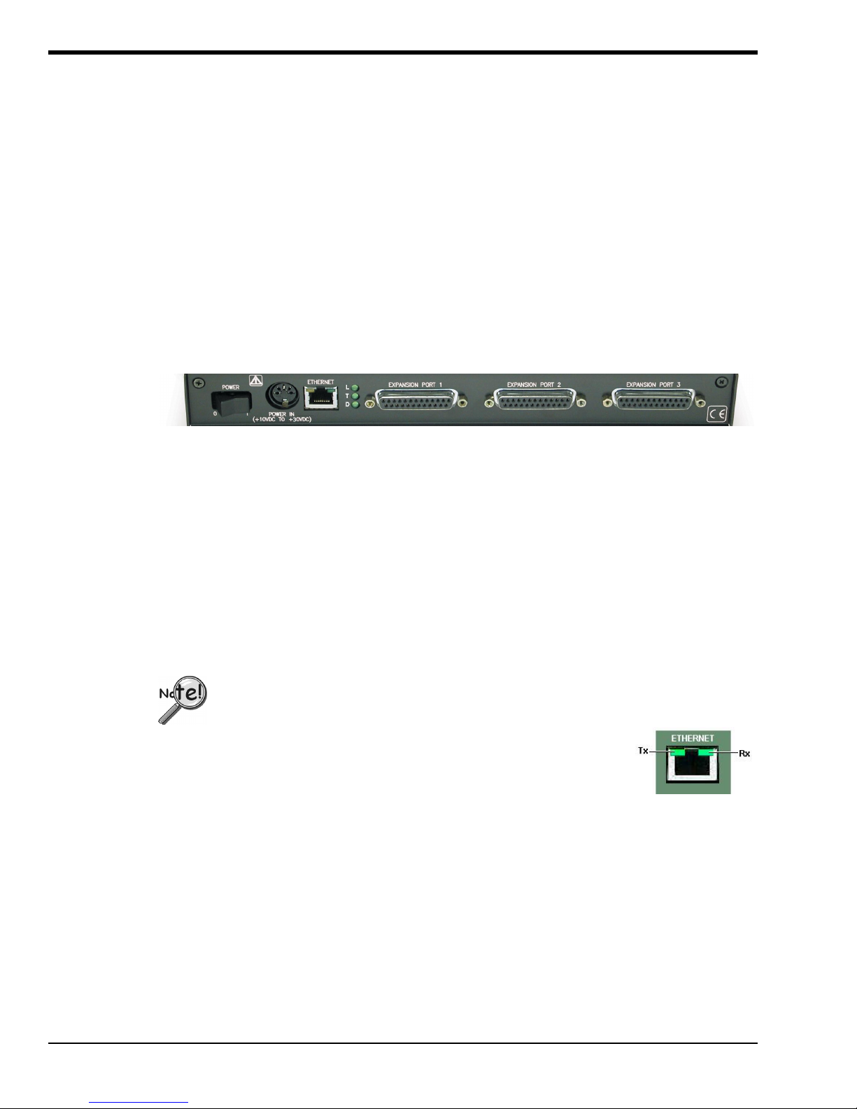
WBK25, Rear Panel
POWER Switch: A rocker-type switch with a “0” label for Power Off, and a “1” for Power On.
DIN5 POWER IN: +10 to +30 VDC, through a socket type DIN5 connector on the chassis. Power is
typically supplied from a TR-40U power adapter.
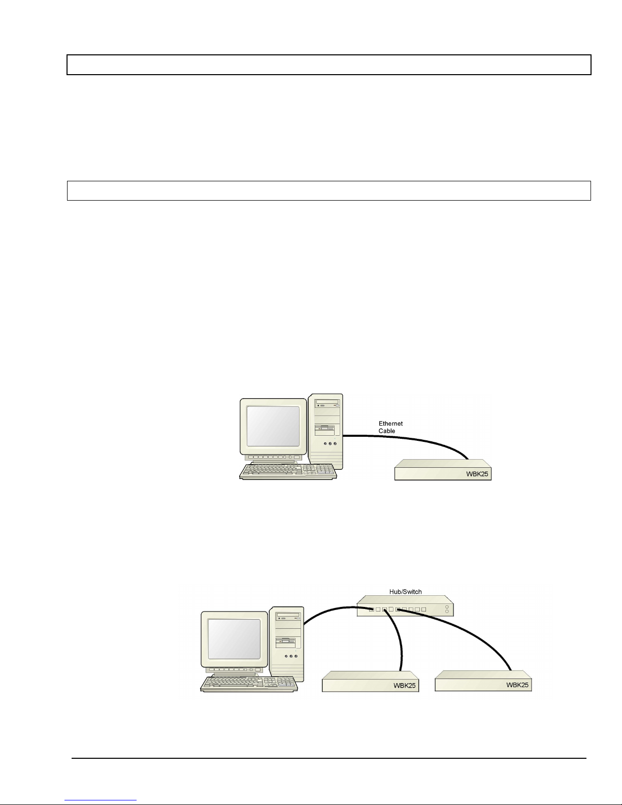
ETHERNET: The 10/100BaseT Ethernet port can connect to the Ethernet port of the host PC, or to an
Ethernet network. Either of two Ethernet patch cables may be used to make the connection. CA-242 is
a
1.5-foot long cable. CA-242-7 is a 7-foot long cable. Note that the Ethernet connector has two built in
LEDs (Tx and Rx) that indicate traffic flow. These are discussed with the three other Ethernet-related
LEDs.
To be CE compliant, the length of the Ethernet cable can not exceed 10m.
LEDs:There are 5 ETHERNET Status LEDS. Two rectangular LEDs (Tx and
Rx) are built into the frame of the Ethernet port. The other three LEDs,
located just to the right of the Ethernet port, are round and are labeled
L, T, and D for Link, BaseT, and Duplex, respectively.
Tx – “ON” indicates traffic is being transmitted (see following figure).
Rx – “ON” indicates that the port is receiving traffic.
L (Link) “ON” indicates a link exists. “OFF” indicates no link.
T(BaseT) “ON” indicates 100BaseTx; “OFF” indicates 10BaseT.
D (Duplex) “ON” indicates full duplex, which allows simultaneous
two-way data traffic. “OFF” indicates half-duplex, which
only allows one-way data traffic at any given time.
Tx and Rx LEDs
EXPANSION PORTS 1, 2, and 3:The three parallel ports are used to expand the system with up to
three additional devices. Each of these ports can be connected to the parallel port of a WaveBook/512A,
/516, /516A, DaqBook/2000A, DaqBook/2000X, WBK40, or a WBK41 via a CA-35-2 (2-foot) or a
CA-35-12 (1-foot) cable.
WBK25, pg. 2 919896 WBK25 Ethernet Interface Module User’s Guide

Operational Aspects
The WBK25 provides an interface for high-speed Ethernet connectivity. The module contains one 10/100BaseT
Ethernet port for connection to a PC’s Ethernet jack or to an Ethernet network hub. The WBK25 also includes three
parallel ports, which are designated as “expansion ports.” Each port can be attached to a to one device, such as a:
WaveBook/512A, /516, /516A, DaqBook/2000A, DaqBook/2000X, WBK40, or a WBK41.
WBK25’s three parallel ports are labeled as expansion ports 1 through 3. They are used to
connect to WaveBook, DaqBook, WBK40, and WBK41 systems via parallel cables. The ports
cannot be used for other parallel devices, such as printers and scanners.
Data transfer rates with the WBK25 depend on the network to which it is attached. If the WBK25 is used in a
point-to-point configuration, where the WBK25 and the PC are the only devices on the network, then data transfers
that exceed 2 Mbytes per second can be expected. The point-to-point scenario is recommended for WaveBook
applications where data transfer speeds may be critical.
A single WaveBook, attached to a WBK25, can operate at its maximum 1 Msamples/s sampling rate while
transferring data continuously to the PC. If the application requires that more than one WaveBook be attached to
one WBK25, with each operating at its maximum 1 Mreading/s sampling rate, contact the factory for the latest
information on data transfer rates. We will continue to improve the WBK25’s data transfer rates as PCs and
networks themselves increase in speed. Users will be able to perform the upgrades in the field.
If the WBK25 is used with DaqBook/2000A, DaqBook/2000X, and/or WBK40 series options, then up to three of
these devices can be attached to one WBK25 and will be capable of simultaneously transferring data at their
maximum sampling rate.
If the WBK25 is attached to a shared Ethernet network the data transfer rates will be dependent on the network
traffic at the time. It is not possible to guarantee maximum data transfer rates in this mode. However, the
WaveBook offers internal memory option cards (WBK30 series) for applications such as this, so that the acquired
data can be locally stored in the event that the shared network traffic prohibits the WaveBook from transferring data
at the same rate at which it was acquired.
Note: It is possible to attach multiple WBK25 units to a single PC that has more than one Ethernet port. It is also
possible to attach several WBK25 units to a multi-port Ethernet hub. Performance under these conditions
will be dependent on the PC’s ability to handle multiple networks.
WBK25 Ethernet Interface Module User’s Guide 919896 WBK25, pg. 3

Connecting a WBK25 to the Ethernet
Introduction
The WBK25 connects directly to an Ethernet port on a PC or network hub via the unit’s built-in
10/100BaseT Ethernet interface. An Ethernet patch cable CA-242 (1.5 foot) or CA-242-7 (7 foot) cable is
used to make the connection.
CAUTION
Turn off power to the system devices and externally connected equipment before
connecting cables. Electric shock or damage to equipment can result even under low-
voltage conditions.
Take ESD precautions (packaging, proper handling, grounded wrist strap, etc.)
Reference Note: Adobe PDF versions of user
manuals will automatically install onto your
hard drive as a part of product support. The
default location is in the Programs group,
which can be accessed from the Windows
Desktop. You can also access documents
directly from the data acquisition CD via the
<View PDFs> button located on the CD’s
opening screen.
Minimum System Requirements
PC system with Pentium®Processor
Windows Operating System
RAM, as follows:
32 Mbytes of RAM for Windows NT
64 Mbytes of RAM for Windows 2000
64 Mbytes of RAM for Windows XP
Contact the factory or your service representative in regard to Ethernet connectivity if
your operating system is other than Windows NT, Windows 2000, or Windows XP.
WBK25, pg. 4 919896 WBK25 Ethernet Interface Module User’s Guide

STEP 1 – Install the Software
1. Remove previous version Daq drivers, if present. You can do this through Microsoft’s Add/Remove
Programs feature.
2. Place the Data Acquisition CD into the CD-ROM drive. Wait for PC to auto-run the CD. This may take a
few moments, depending on your PC. If the CD does not auto-run, use the Desktop’s Start/Run/Browse
feature to locate and run the CD’s setup.exe file.
3. After the intro-screen appears, follow the screen prompts.
STEP 2 – Determine the type of Network Connection
To properly connect a WBK25 you must determine the type of network that it will become part of. This is
because the type of network used has a direct bearing on the IP address that will be assigned.
Briefly, the four network types are as follows:
Dedicated Network - with a direct cable connection from the PC to the device•
•
•
•
Dedicated Network - making use of a network hub or switch
LAN with a DHCP Server
(Local Area Network with a Dynamic Host Configuration Protocol)
LAN with no DHCP Server
(Local Area Network with no Dynamic Host Configuration Protocol)
Dedicated Network - with a direct cable connection from the PC to the device
In this scenario the WBK25 is connected directly to an Ethernet jack on a host computer.
Dedicated Network using a Direct Cable Connection
Dedicated Network - making use of a network hub or switch
In this scenario the WBK25 is connected to the Ethernet through a network hub or switch. At least one
computer is also connected to the hub.
Dedicated Network using a Hub/Switch
WBK25 Ethernet Interface Module User’s Guide 919896 WBK25, pg. 5

Some network devices such as a wireless access point may act as a DHCP server. If this is
the case, follow the instructions for the LAN with DHCP server. For detailed information
consult the documentation that is specific to your network device.
LAN with a DHCP Server (Local Area Network with a Dynamic Host Configuration Protocol)
Many corporations use the LAN/Server with DHCP arrangement for their networks. In this type of setup
several computers are typically connected to a network that makes use of a DHCP server. In addition, one
or more WBK25 modules are connected to the network hub/switch.
LAN with a DHCP Server
Notes:
Using the WBK25 on a typical LAN may affect the speed of the network and internet data
transfer. Because of this we recommend adding a network card to the computer and using one
of the two dedicated network configurations.
➣
➣ Contact your network administrator before connecting a WBK25 to a corporate network.
LAN with no DHCP Server
(Local Area Network with no Dynamic Host Configuration Protocol)
This scenario looks the same as that shown in the previous illustration, except there is no Dynamic Host
Configuration Protocol (DHCP). In this type of setup one or more computers are connected to a network
and each computer has a static IP address.
WBK25, pg. 6 919896 WBK25 Ethernet Interface Module User’s Guide

STEP 3 –Connect the WBK25 to the Ethernet
Reference Note:
For examples of system connections, including cable use, refer to the following documents, as applicable:
For DaqBook/2000 Series systems refer to the section entitled Examples of System Expansion in the
DaqBook/2000 Series Installation Guide (p/n 1103-0940) or the DaqBook/2000 Series User’s
Manual (p/n 1103-0901).
For WaveBook systems refer to the System Enhancement and Expansion section of the WaveBook
User’s Manual (p/n 489-0901).
What you will need to connect a WBK25 to the Ethernet:
• An available connection to the Ethernet. The connection can be either
- an Ethernet jack on a computer or
- an Ethernet jack on a hub that is connected to the Ethernet.
• An Ethernet patch cable, e.g., a CA-242 (1.5 foot cable) or a CA-242-7 (7-foot cable).
1. Connect the Ethernet cable to the Ethernet jack on the WBK25.
2. Connect the other end of the Ethernet cable to the Ethernet jack on the host computer or
network hub.
STEP 4 – Power-up the WBK25
What you will need:
A power supply with a range of +10 VDC to +30 VDC.
The power supply needs to have a male DIN5 connector.
Note: The switching-mode power supply that is commonly used with these systems has an input
range of 100 VAC to 240 VAC at 50 Hz to 60 Hz. The power supply’s output [to the
device] is typically 15 VDC @ 2.7 amps via a DIN5 connector.
Note: Various AC adapter models support power grids of USA, Europe, Japan, and Asia.
How to make the connection:
1. Place the WBK25’s power switch in the “OFF” (0) position, if it is not already OFF.
2. Connect the DIN5 end of the adapter’s cable to the power in connector on the WBK25.
3. Connect the adapter’s plug to a standard AC outlet.
4. If your adapter has a power switch, position it to “ON.”
5.
Turn ON the WBK25by placing the power switch to the “1” position.
The power led will light up.
WBK25 Ethernet Interface Module User’s Guide 919896 WBK25, pg. 7

The power management and power requirements sections of the associated user’s
manual(s) should be reviewed prior to powering up a system.
For DaqBook/2000 Series systems refer the DaqBook/2000 Series User’s Manual
(p/n 1103-0901).
For WaveBook systems refer to the WaveBook User’s Manual (p/n 489-0901).
The PDF versions of these documents can be accessed from the data acquisition CD via the
<View PDFs> button on the CD’s opening screen.
STEP 5 - Configure the Computer’s Network Settings [Applies to “dedicated networks” only]
If using a LAN (Local Area Network), which has a DHCP server, skip this section and continue
with STEP 7 - Configure and Test the System using the Daq*Configuration Applet (page 12).
If using a LAN (Local Area Network), which has no DHCP server, skip this section and
continue with STEP 6 - Configure Device Network Settings using DaqIPConfig (page 10).
1. Open the Control Panel by navigating from the Windows Desktop as follows:
Start Menu ⇒Settings ⇒Control Panel.
2. Double-click the “Network and Dial-up Connections” icon.
3. Double-click the “Network Connection” icon for the network that the WBK25 is connected
to.
Local Area Connection Status
4. In the “Local Area Connection Status” box (previous figure), click on the <Properties>
button. The “Local Area Connection Properties” box will appear (following figure).
WBK25, pg. 8 919896 WBK25 Ethernet Interface Module User’s Guide

Local Area Connection Properties
5. Double-click the “Internet Protocol (TCP/IP)” component (previous figure).
The “Internet Protocol (TCP/IP) Properties” box will appear (following figure).
Internet Protocol (TCP/IP) Properties
WBK25 Ethernet Interface Module User’s Guide 919896 WBK25, pg. 9

Configure the Computer’s TCP/IP settings as follows.
Internet Protocol (TCP/IP) Properties
6. Select the “Use the following IP Address” radio button.
7. Set the IP address field to 10.0.0.x where x is some number from 1 to 255.
Make sure that each computer on the dedicated network has a unique IP address.
8. Set the Subnet mask to 255.0.0.0. Note that the remaining fields can be left unchanged.
STEP 6 - Configure Device Network Settings using DaqIPConfig
Applies only to a LAN (Local Area Network), which has a no DHCP server.
If using a LAN (Local Area Network), which has a DHCP server, skip this section and continue with
STEP 7 - Configure and Test the System using the Daq*Configuration Applet (page 12).
The DaqIPConfig applet, designed for 32-bit Windows /NT/2000/XP systems. DaqIPConfig allows you to change
the IP address of a device to match the address of a host computer. The applet is located in the program group for
the associated device and can be accessed from the Windows Desktop via the start menu.
1. Locate the DaqIPConfig Applet.
Locate the DaqIPConfig applet by navigating from the Windows’ Desktop as follows:
DaqBook Users: Start Menu ⇒Programs ⇒IOtech DaqX Software ⇒DaqIPConfig
WaveBook Users: Start Menu ⇒Programs ⇒IOtech WaveBook Software ⇒DaqIPConfig
2. Open the DaqIPConfig Applet.
Click on the DaqIPConfig selection to open the applet.
WBK25, pg. 10 919896 WBK25 Ethernet Interface Module User’s Guide

DaqIPConfig
3. Select the device that is to have the address change.
Note: In the above figure there is only one device to select, i.e., WBK25.
4. Set the internet protocol (TCP/IP) settings to be compatible with host computer.
a. Select the radio button labeled “Use the following IP address.”
b. Enter the new internet protocol settings. If needed, consult your network administrator for
acceptable numbers.
c. Click the <OK> button.
5. Reboot the device.
The new IP address will not take affect until the device has been powered-off, then powered back on.
6. Repeat steps 3, 4, and 5 for other devices in the system.
After configuring the network settings for all devices, proceed to Step 7.
WBK25 Ethernet Interface Module User’s Guide 919896 WBK25, pg. 11

STEP 7 - Configure the System using the Daq* Configuration Applet
The Daq* Configuration applet, designed for 32-bit Windows 95/98/Me/NT/2000/XP systems, is located in the
Windows Control Panel. It allows you to add or remove a device and change configuration settings.
1. Open the Daq* Configuration Applet.
a. Open the Control Panel by navigating from the Windows’ Desktop as follows:
Start Menu ⇒Settings ⇒Control Panel
b. From the Control Panel, double-click the Daq* Configuration icon.
2. Add the WBK25 to the list of installed devices.
The first-level device is the device that will be connected directly to the Ethernet, via a host computer’s
Ethernet jack or a jack on a network hub. The WBK25 is a first-level device.
a. Select the Computer image in the Device Inventory configuration tree (following figure).
b. Click the <Add Device> button. The “Select Device Type” box will appear.
c. Select the WBK25 from the list of devices, as applicable.
d. Click the <OK> button. The “Properties” box will appear for the selected device.
Using Daq* Configuration Device Inventory & Select Device Type to Add a Device
WBK25, pg. 12 919896 WBK25 Ethernet Interface Module User’s Guide

3. Set the properties of the WBK25.
In this step you will set the device properties according to one of the following two methods, depending on
whether you have a “Dedicated Network” or a “LAN with DHCP Server Network.” Illustrations of the
network types are provided on page 5.
Users of Dedicated Networks follow these 3 steps.
a. Enter the Serial Number of the first-level device (WBK25). In the following screen shots
the Serial Number is 800000.
b. Select the “Auto IP Setting” radio button. Note that the IP Address of the WBK25 will
automatically be calculated and displayed in the IP Address field as indicated in the following
left-hand figure.
c. Click the <OK> button.
For DEDICATED Networks
For LAN with DHCP Server Networks
Daq* Configuration, Properties Dialog Boxes
Users of LAN with DHCP Server Networks follow these 4 steps.
The DaqIPConfig applet provides the Serial Number and the IP Address of the device. Users of LAN
with DHCP Server Networks will need to enter both numbers in the Daq* Configuration, Properties
dialog boxes (previous right-hand figure). Page 10 includes instructions for accessing DaqIPConfig.
If needed, refer to the upper right-hand figure in regard to radio-button and data entry locations.
a. Enter the base 10 version of the Serial Number of the
WBK25.
b. Select the “Manual IP Setting” radio button.
c. In the IP Address field, enter the IP address.
d. Click the <OK> button.
Partial View of DaqIP Config
Showing IP Addresses & Serial Numbers
Provide your network administrator with the information on the device’s MAC label.
Also, find out from the administrator if the IP Address will be changing. If so, see if you
can obtain a permanent IP Address dedicated specifically to your device.
WBK25 Ethernet Interface Module User’s Guide 919896 WBK25, pg. 13

4. Test the system connections.
Before testing the system, make sure the device has been properly installed and powered-on. Make sure all
cables are properly and securely connected.
If the unit does not respond within 30 seconds perform the following steps:
1) reboot the system
2) upon power-up, re-open the Daq* Configuration applet
3) select another configuration setting
4) reinitiate the test
How to run the TCP/IP Test (The TCP/IP test is for Ethernet devices only)
The TCP/IP (Transmission Control Protocol/Internet Protocol) test is for Ethernet devices only. The test is
accessed and initiated as follows.
a. Open the Control Panel by navigating from the Windows’ Desktop as follows:
Start Menu ⇒Settings ⇒Control Panel
b. From the Control Panel, double-click the Daq* Configuration icon.
c. Select the device that you want to test from the Device Inventory configuration tree.
d. Click the <Properties> button. The Properties dialog box will open.
e. Click the “Test Hardware” tab.
f. Click the <TCP/IP Test> button.
Results of a TCP/IP Test
WBK25, pg. 14 919896 WBK25 Ethernet Interface Module User’s Guide

What does the TCP/IP test tell me?
The TCP/IP test provides test results for “Pinging Device” and “TCP Connection Test.”
Pinging Device.The Pinging Device test is an ICMP (Internet Control Message Protocol) ping test. In
addition to indicating either “Passed” or “Failed,” the test displays;
(a) The round-trip time of the ping, for example, <10 ms.
(b) Packet Loss expressed as a percent of data lost.
A long ping round trip time, for example, >50 ms and/or any packet loss indicates a slow network that is
not optimized.
If the Pinging Device Test fails a <Details> button will appear just above the <Resource Test> button. If
this is the case, click the <Details> button to obtain possible causes and possible solutions.
TCP (Transmission Control Protocol) Connection Test.The result of the TCP test will be either
passed or failed. If the TCP test failed a <Details> button will appear. If this is the case, click the
<Details> button to obtain possible causes and possible solutions.
This completes the procedure for connecting a WBK25 to the Ethernet. At this point you should refer to
the more detailed user documentation that applies to the other devices that are included in your data
acquisition system, e.g., WaveBooks, WBK options, DaqBooks, and DBK options. User manuals typically
include pinouts, information on system explanation, data acquisition, and links to software and
programming documents (in PDF format).
Reference Notes:
For additional device and system information:
➣
➣
➣
DaqBook/2000 Series users should refer to the DaqBook/2000 Series User’s Manual,
(p/n 1103-0901) and the DBK Options Manual (p/n 457-0905).
WaveBook and WBK option users should refer to both the WaveBook User’s Manual,
(p/n 489-0901) and the WBK Options Manual (p/n 489-0902).
Programming information is contained in the Programmer’s Manual, (p/n 1008-0901).
Note: You can access PDF documents directly from the opening screen of the data acquisition CD
via the <View PDFs> button.
WBK25 Ethernet Interface Module User’s Guide 919896 WBK25, pg. 15

Fuse Replacement
CAUTION
Turn OFF the power to, and UNPLUG the WBK25 Ethernet Interface Module and all
connected equipment. Electric shock or damage to equipment can result even under
low-voltage conditions.
Take ESD precautions, to include using a grounded wrist strap.
Use care to avoid touching board surfaces and onboard components. Ensure boards
do not come into contact with foreign elements such as oils, water, and industrial
particulate.
You should only replace a fuse if your device shows no sign of damage. If your device
appears damaged, such as evidenced by a “smoked” component, contact the factory as
soon as possible.
If the replacement fuse blows contact the factory as this indicates a problem may
exist with your WBK25 module.
Each WBK25 Ethernet Interface Module has one user-replaceable fuse designated as F201.
F201 Input Power Fuse. 4.0 A, MINI ATO.
This 4-amp fuse is located near the rear panel’s 5DIN POWER IN connector.
If this fuse has blown, the WBK25 module will not power up.
Factory Part Number: FU-8-4
Littelfuse Part Number: 297-004, Littelfuse Body Color Code: Pink
You will need the following:
Phillips Screwdriver•
•
•
•
3AG Fuse Puller, or needle-nose pliers*
Grounding wrist strap and associated anti-static pad
Replacement fuse F201
* Needle-nose pliers can be used to pull MINI ATO fuses; but should not be used to insert fuses.
1. If you have not already done so, turn OFF the power to, and UNPLUG the WBK25 module
and all connected equipment. Remove all lines from the unit.
2. Using a Phillips screwdriver, remove the 4 cover plate screws and the cover plate (not shown).
WBK25, Fuse and Cover Plate Screw Locations
Cover Plate
Screws (2 of 4)
Cover Plate
Screws (2 of 4)
Fuse F201
WBK25, pg. 16 919896 WBK25 Ethernet Interface Module User’s Guide

3. Locate fuse F201 near the Power In DIN 5 Connector (left edge of the rear panel, see figure).
4. While wearing a grounded wrist strap, remove and replace the bad fuse. Ensure that the new
fuse is fully seated.
5. Replace the cover plate and secure it to the chassis with the 4 screws that were removed in
step 2.
6. Return the WBK25 Ethernet Interface Module to normal service. Should any problems be
noted consult the factory.
Specifications
Environment
Operating: 0 to 50°C (32° to 122°F); 0 to 95% humidity, non-condensing
Storage: -20° to 70°C (-4° to 158°F)
Power: 0.75A @ 15V
Fuse:F201 Input Power Fuse. 4.0 A, MINI ATO. Factory Part Number: FU-8-4
Littelfuse Part Number: 297-004, Littelfuse Body Color Code: Pink
Dimensions: 285 mm W x 220 mm D x 35 mm H (11” x 8.5” x 1.375”)
Ethernet Interface: 10/100BaseT
Ethernet Connector: RJ45
Parallel Interface: Three EPP (Enhanced Parallel Ports)
Parallel Connectors: DB25, female
Accessories & Cables Part No.
Fastener-panel kit for WBK series 262-0801
Fastener-panel kit for DBK series 232-0810
Fastener-panel handle HA-111
DB25 male to DB25 female parallel cable, 2 ft. CA-35-2
DB25 male to DB25 female parallel cable, 1 ft. CA-35-12
Ethernet patch cable, 1.5 ft. CA-242
Ethernet patch cable, 7 ft. CA-242-7
Note: WBK25 is supported in the 32-bit driver only.
WBK25 Ethernet Interface Module User’s Guide 919896 WBK25, pg. 17

WBK25, pg. 18 919896 WBK25 Ethernet Interface Module User’s Guide

Ethernet CE Kit Installation Instructions
Introduction
The Ethernet CE Kit includes three ferrite clamp-on inductive collars to reduce EMI. It also includes a ground-line for
safety. The kit is simple to install and consists of the following components.
•
3 Ferrite Inductive Collars with Tie-wrap, p/n L-8-1
•
1 Ground-Line, p/n CA-250
•
4 Washers, #8 External Tooth, p/n WA-5 – used to lock screws (2 washers per screw)
•
1 Screw, #8-32x1/4 Phillips Pan-head, p/n HA-154-4 – used to secure the ground-line to a
threaded splice-plate hole on the data acquisition device
•
1 Screw, #6-32x5/16 Phillips Pan-head, p/n HA-2-5 – used to secure the ground-line to the PC
Connect the Ground Line
1. If using a desktop or tower PC, (a) remove a screw that secures the computer casing to
the chassis. The first photo shows a good connection point for the PC ground. (b) Use
the #6-32x5/16 screw and two #8 tooth washers, orientated as illustrated, to secure one
end of the ground line to the PC chassis.
If using a notebook (laptop) PC, connect one end of the ground-line to a known earth
ground. Depending on the ground chosen, you may need to use a screw other than the
one supplied.
2. On the data acquisition device, locate an available threaded splice-plate hole. This will
be used for attaching the ground line to the device, as indicated in the second photo.
3. Use the #8-32x1/4 screw and two #8 tooth washers, orientated as illustrated, to secure
the free end of the ground line to the chassis of the data acquisition device. The second
photo shows such a connection.
Install the Ferrite Inductive Collars
1. Place one ferrite collar at each end of the Ethernet cable.
Snap the two collars shut. See photos.
2. Place the remaining ferrite collar next to the DIN5 connector on the
power cable. Snap the collar shut.
3.
Use a tie-wrap (one per ferrite collar) to secure each collar to its
respective cable.
This partial view of the host PC shows the
Ethernet cable with a ferrite collar. The
PC’s connection to the ground-line is also
visible.
Tie-wrap goes through
this opening.
4. (Optional) Trim the excess tie-wrap material. While trimming
use care to avoid cutting into the cables.
This completes the installation.
This partial view of the data acquisition
device shows its connection to the ground-
line. It also shows two ferrite collars, the
foremost of which is clamped to the power
cable. The background collar is clamped
onto the Ethernet cable.
928396 p./n 1077-0901, rev 1.0

WBK25, pg. 20 919896 WBK25 Ethernet Interface Module User’s Guide
Table of contents
Other IOtech Recording Equipment manuals