Installation Hotline • 866.EZINPRO
Inprocorp.com • 800.222.5556 • 262.679.9010
World Headquarters S80 W18766 Apollo Drive, Muskego, WI 53150 USA
Installation Instructions
2000/2000W/G2-2000 Handrail
Please read all instructions before installing
handrail.
LEFT RETURN
(3 15
/16" [99mm] ALLOWANCE)
RETAINER
BUTT JOINT
HANDRAIL
SPLICE
RIGHT RETURN
(3 15
/
16" [99mm] ALLOWANCE)
INSIDE/OUTSIDE CORNER, 90º
(5 3/8" [136mm] ALLOWANCE FOR INSIDE C
(1/4" [6mm] ALLOWANCE FOR OUTSIDE CORNER)
CORNER, 135º
(2 3/8" [62mm] ALLOWANCE FOR INSIDE CORNER)
1/4" [6mm] ALLOWANCE FOR OUTSIDE CORNER)
BOTTOM
PLATE
(Included with left return)
BOTTOM PLATE
(Included with right return)
CONTINUOUS
ALUMINUM RETAINER
.080" [2mm]
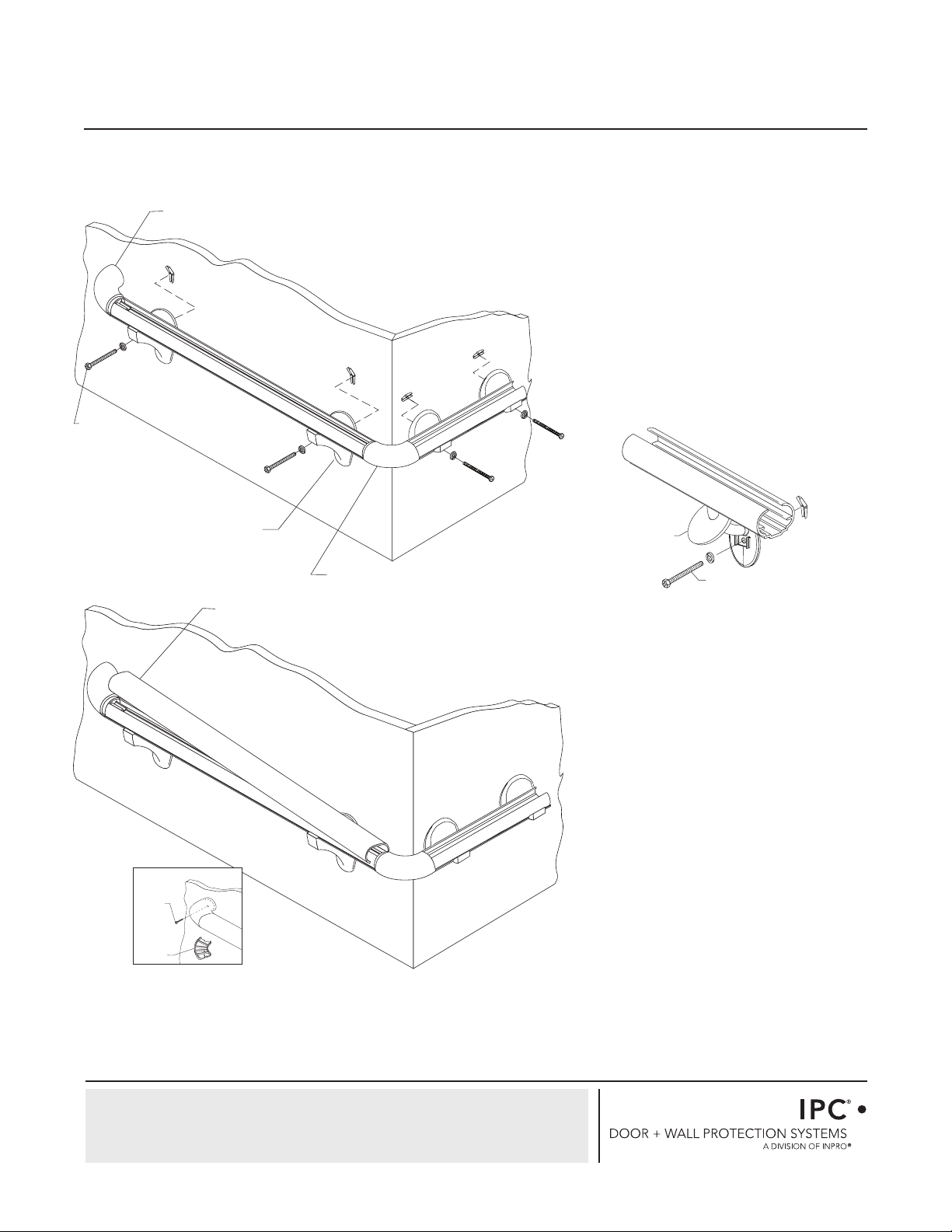
FIG. 1
FIG. 2
2. Drill holes in centerline of aluminum retainer
for brackets, returns and corners using 1/4"
(6mm) drill bit. Attach returns, inside corners
and outside corners to retainer leaving a 1/16"
(1.5mm)gap between returns/corners and
retainer to allow for adjustment. See Figure 2.
a. Plastic Brackets - Attach brackets to retainer.
See Figure 2a.
b. Stainless Steel Brackets - Slip stainless steel
cover over post. Insert post through retainer
hole and attach. See Figure 2b.
DRILL 4" [102mm] FROM EACH END
FOR BRACKETS
SPACE HOLES
A MAXIMUM OF
EVERY 32" [812mm]
FOR BRACKETS
DRILL 1/2" [13mm]
FROM
EACH END
FOR RETURNS
AND CORNERS
TURN
INSIDE/OUTSIDE
CORNER
11/8" SLOTTED
PAN HEAD
BOLY ASSEMBLY
11/8"SLOTTED
PAN HEAD BOLT
ASSEMBLY
MOUNTING
BRACKET
1
/
4
” SERRATED
FLANGE
HEX NUT
STAINLESS STEEL
CKET ASSEMBLY
1/4” SERRATED
FLANGE
HEX NUT
FIG. 2A
FIG. 2b
1. Cut aluminum retainer to desired length,
leaving allowance for returns, outside corners
and inside corners. See Figure 1.