IPCOMM SEC3M User manual

Subject to alterations Version 1.4
IPCOMM GmbH - 2 - SEC3x Manual
Walter-Bouhon-Strasse 4 Copyright © IPCOMM GmbH, 2021
90427 Nuremberg All rights reserved
Germany
Table of Contents
1Introduction...................................................................................................................................... 3
2Hardware Description...................................................................................................................... 4
2.1 General.................................................................................................................................... 4
2.2 IEC 61850-3; EN 61850-3 ....................................................................................................... 4
2.3 Controls and Display Elements ............................................................................................... 5
2.3.1 SEC3 / SEC3-SA............................................................................................................. 5
2.3.2 SEC3PB........................................................................................................................... 6
2.3.3 SEC3IO / SEC3IO-SA ..................................................................................................... 7
2.3.4 SEC3M ............................................................................................................................ 8
2.4 Hardware Components............................................................................................................ 9
2.4.1 Mainboard........................................................................................................................ 9
2.4.2 RS-232/RS-422/RS-485 Interfaces................................................................................. 9
2.4.3 Network Interfaces........................................................................................................... 9
2.4.4 PROFIBUS .................................................................................................................... 10
2.4.5 I/O Interfaces ................................................................................................................. 11
2.4.6 Mobile Network Interfaces............................................................................................. 12
2.4.7 Flash (Mass Storage) .................................................................................................... 12
2.4.8 Lithium Battery............................................................................................................... 13
2.4.9 Power Supply................................................................................................................. 14
2.4.10 State Relay „FAIL“ ......................................................................................................... 14
3Diagnostic LEDs............................................................................................................................ 15
3.1 CPU ....................................................................................................................................... 15
3.2 SEC3M –Cellular Modem..................................................................................................... 16
3.3 SEC3PB - PROFIBUS........................................................................................................... 16
3.4 SEC3IO - DIGITAL INPUT/OUTPUT..................................................................................... 17
3.4.1 Digital Inputs.................................................................................................................. 17
3.4.2 Digital Outputs ............................................................................................................... 17
4Technical Data Sheet .................................................................................................................... 18
5EU Declaration of Conformity........................................................................................................ 19
6Nomenclature of SEC3x Item Code .............................................................................................. 20
7SEC3x Dimensions........................................................................................................................ 21
7.1.1 SEC3 ............................................................................................................................. 21
7.1.2 SEC3PB......................................................................................................................... 21
7.1.3 SEC3IO.......................................................................................................................... 22
7.1.4 SEC3M .......................................................................................................................... 22

Subject to alterations Version 1.4
IPCOMM GmbH - 3 - SEC3x Manual
Walter-Bouhon-Strasse 4 Copyright © IPCOMM GmbH, 2021
90427 Nuremberg All rights reserved
Germany
1 Introduction
All technical information, descriptions and illustrations contained in this ‘Operating, Maintenance, and
Installation Manual’ remain our property and shall not be used differently than for operating this system,
nor shall they be copied, reproduced or passed on to third parties or brought to their notice without our
prior written consent.
The information represented in this manual is in keeping with current standards and is subject to
subsequent alterations.
This manual contains important instructions referring to safe installation, commissioning, operation, and
maintenance.
Read this manual thoroughly, before starting up the gateway, and observe the instructions.
In order to comply with the guidelines for electro-magnetic compatibility in embedded controllers, only
CE-certified components are used in compliance with project-specific requirements.
Please note that the hardware platform (SEC3x) is not protected against lightning and the operator
should, if desired, take appropriate protective precautions.
The addition of our RS-232 isolator provides efficient protection of your data and equipment against
external influences. We will be pleased to draw up a non-binding offer for you.
Finally we want to draw your attention to the fact that any warranties with respect to the embedded
controller will be invalid in the event that:
Operation, servicing, and maintenance are not carried out accurately according to the
instructions; repairs are not carried out by our personnel or without our prior written consent.
Commissioning is not carried out by our personnel or we have not given our approval for the
commissioning or the commissioning is carried out by untrained personnel.
The unit is used inadequately, incorrectly, negligently, or inappropriately or for a purpose other
than originally intended.
The serial number is removed from the product.
For your protection, observe the following safety precautions when setting up your equipment:
Follow all cautions and instructions marked on the equipment.
Ensure that the voltage and frequency of your power source match the voltage and frequency
inscribed on the equipment's electrical rating label.
Never push objects of any kind through openings in the equipment. Dangerous voltages may
be present. Conductive foreign objects could produce a short circuit that could cause fire,
electric shock, or damage to your equipment.
All trade names or trademarks mentioned in this document are used for identification purposes only and
are property of their respective owners.

Subject to alterations Version 1.4
IPCOMM GmbH - 4 - SEC3x Manual
Walter-Bouhon-Strasse 4 Copyright © IPCOMM GmbH, 2021
90427 Nuremberg All rights reserved
Germany
2 Hardware Description
2.1 General
This embedded controller has been designed for industrial environments and offers a high degree of
flexibility, performance, and reliability.
All components are cooled passively.
Factors like quality, availability, and high durability are of particular importance for the selection of our
components.
Exhaustive tests of the embedded controller are performed by our company. Each device undergoes an
in-depth function test. This function test includes a burn-in test with full communication on all interfaces
(min. 48 hours). Communication disruptions, transmission errors, and every important component with
regard to function, temperature, voltages etc. are monitored. Hundreds of restarts are executed whereby
connections to all interfaces are re-established at each reboot.
Quality assurance is conducted according to the four-eye principle. Each device passes a number of
quality inspections.
The DIN rail mounting clip can show signs of usage due to the functional tests carried out.
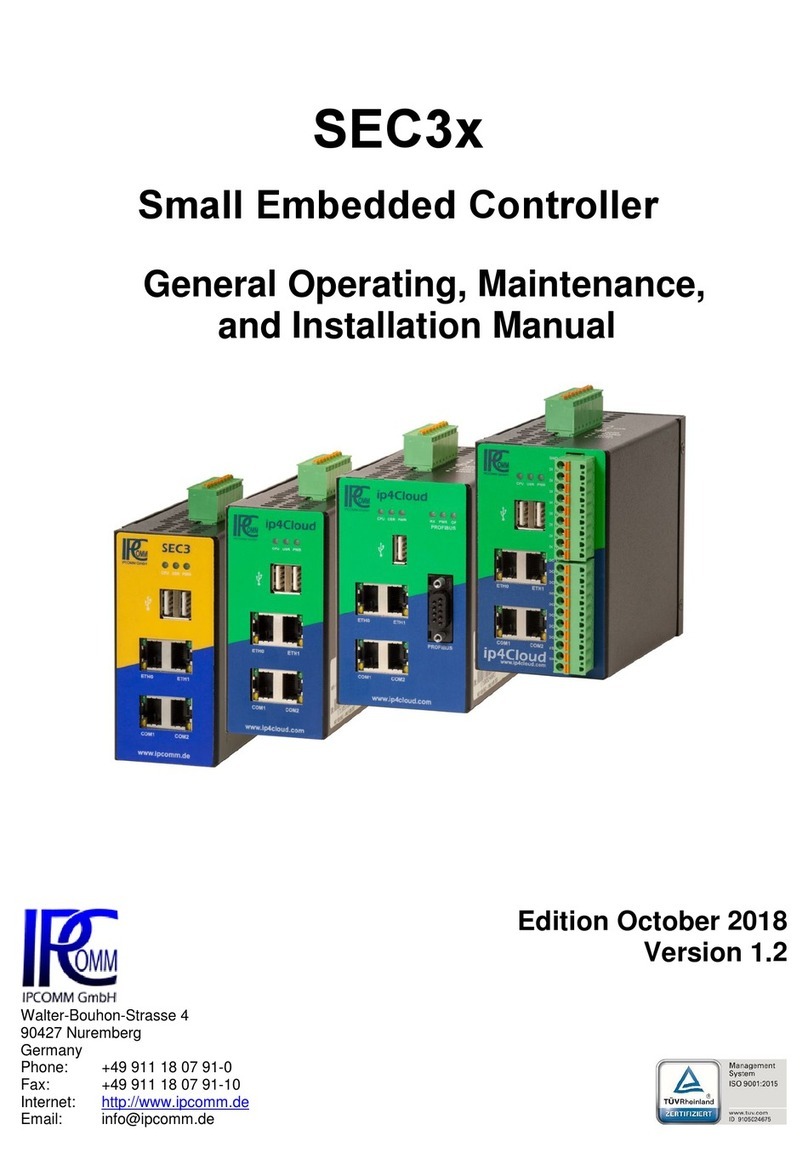
The SEC3x is available in the following variants:
SEC3 - The Base Model
SEC3PB - The PROFIBUS Sniffer
SEC3IO - The I/O Controller
SEC3M The Base Model with Cellular Modem
2.2 IEC 61850-3; EN 61850-3
The particular requirements of the IEC 61850-3 standard for electromagnetic compatibility and power
supply are met by the following hardware models:
SEC3-SA - The Base Model
SEC3IO-SA - The I/O Controller

Subject to alterations Version 1.4
IPCOMM GmbH - 5 - SEC3x Manual
Walter-Bouhon-Strasse 4 Copyright © IPCOMM GmbH, 2021
90427 Nuremberg All rights reserved
Germany
2.3 Controls and Display Elements
2.3.1 SEC3 / SEC3-SA
Figure 1: SEC3 front view
Figure 2: SEC3 rear view
Diagnostic LEDs:
CPU, User, Power
COM2
port
COM1
port
Power supply
connection 1 & 2,
"Fail" contact
USB
ports
ETH0
port
ETH1
port
Device Label:
Model (type), item
no., serial number,
operating voltage
DIN rail
mounting clip

Subject to alterations Version 1.4
IPCOMM GmbH - 6 - SEC3x Manual
Walter-Bouhon-Strasse 4 Copyright © IPCOMM GmbH, 2021
90427 Nuremberg All rights reserved
Germany
2.3.2 SEC3PB
Figure 3: SEC3PB front view
Figure 4: SEC3PB rear view
PROFIBUS
Diagnostic LEDs:
Receive, Power,
Operation
Diagnostic LEDs:
CPU, User, Power
COM1
port
ETH0
port
ETH1
port
PROFIBUS
USB
port
Power supply
connection 1 & 2,
"Fail" contact
COM2
port
Device Label:
Model (type), item
no., serial number,
operating voltage
DIN rail
mounting clip

Subject to alterations Version 1.4
IPCOMM GmbH - 7 - SEC3x Manual
Walter-Bouhon-Strasse 4 Copyright © IPCOMM GmbH, 2021
90427 Nuremberg All rights reserved
Germany
2.3.3 SEC3IO / SEC3IO-SA
Figure 5: SEC3IO front view
Figure 6: SEC3IO rear view
Diagnostic LEDs:
8x digital input
8x digital output
Diagnostic LEDs:
CPU, User, Power
COM1
port
ETH0
port
ETH1
port
Connector strip for
digital inputs resp.
outputs
USB
ports
Power supply
connection 1 & 2,
"Fail" contact
COM2
port
Device Label:
Model (type), item
no., serial number,
operating voltage
DIN rail
mounting clip

Subject to alterations Version 1.4
IPCOMM GmbH - 8 - SEC3x Manual
Walter-Bouhon-Strasse 4 Copyright © IPCOMM GmbH, 2021
90427 Nuremberg All rights reserved
Germany
2.3.4 SEC3M
Figure 7: SEC3M front view
Figure 8: SEC3M rear view
Diagnostic LEDs:
CPU, User, Power
COM1 / COM2
port
ETH0 / Eth1
port
SIM card slot
Mobile radio
diagnostic LED
Power supply
connection 1 & 2,
"Fail" contact
SMA antenna
connectors
Device Label:
Model (type), item
no., serial number,
operating voltage
DIN rail
mounting clip

Subject to alterations Version 1.4
IPCOMM GmbH - 9 - SEC3x Manual
Walter-Bouhon-Strasse 4 Copyright © IPCOMM GmbH, 2021
90427 Nuremberg All rights reserved
Germany
2.4 Hardware Components
2.4.1 Mainboard
The utilized mainboard is an ultra-compact ARM platform with two integrated network interfaces and
two serial interfaces. The heart of the system is powered by a passively cooled ARM processor with 1
GHz, 256 MB system memory, and 512 MB flash memory.
Detailed information on each model (variant) can be found in chapter 4 "Technical data sheet".
2.4.2 RS-232/RS-422/RS-485 Interfaces
COM 1 & 2 can be configured as a RS-232/RS-422/RS-485 interface by the software.
SERIAL PORT
RJ45 female connector
Pin
RS-232
RS-422
RS-485
1
DSR
---
---
2
RTS
TXD+
Data+
3
GND
GND
GND
4
TXD
TXD-
Data-
5
RXD
RXD+
---
6
DCD
RXD-
---
7
CTS
---
---
8
DTR
---
---
Figure 9: Pin assignment RS-232/RS-422/RS-485
LEDs to display transmission and reception of data on the COM interfaces are located directly on the
RJ45 socket. An "RJ45 - DB9 male" adapter cable is available as an option.
2.4.3 Network Interfaces
The embedded controller is equipped with two 10/100 Mbps BaseT (RJ45) interfaces.
LAN PORT
RJ45 female connector
Pin
Signal
1
ETx+
2
ETx-
3
ERx+
6
ERx-
Figure 10: Pin assignment LAN
LEDs to display the link status and the activity of the Ethernet interfaces are located directly on the RJ45
socket.
RXD (yellow)
TXD (green)
Activity (yellow)
Link (green)

Subject to alterations Version 1.4
IPCOMM GmbH - 10 - SEC3x Manual
Walter-Bouhon-Strasse 4 Copyright © IPCOMM GmbH, 2021
90427 Nuremberg All rights reserved
Germany
2.4.4 PROFIBUS
The SEC3PB embedded controller offers a purely passive PROFIBUS DP interface. The injection of
data into the PROFIBUS is physically prevented.
PROFIBUS PORT
DB9 female connector
Pin
Signal
1
---
2
---
3
BUS B (D+)
4
---
5
GND
6
+ 5 V DC
7
---
8
BUS A (D-)
9
---
Figure 11: Pin assignment PROFIBUS
An optional terminating network (bias network) avoids undefined bus levels caused by inactive line
drivers.
Figure 12: PROFIBUS termination

Subject to alterations Version 1.4
IPCOMM GmbH - 11 - SEC3x Manual
Walter-Bouhon-Strasse 4 Copyright © IPCOMM GmbH, 2021
90427 Nuremberg All rights reserved
Germany
2.4.5 I/O Interfaces
The SEC3IO embedded controller features eight digital inputs and eight digital outputs.
The digital inputs are equipped with overvoltage protection.
Digital input
9-pin multipoint connector
Pin
Signal
1
GND
2
DI 1
3
DI 2
4
DI 3
5
DI 4
6
DI 5
7
DI 6
8
DI 7
9
DI 8
Figure 13: Pin assignment digital inputs
The digital outputs are also equipped with overvoltage protection and an additional overcurrent
protection. In case of a fault, the respective digital output switches to a high-impedance state. This
safety-shutdown of a digital output can be reset by setting the specific output to “low” (pin 10 - GND)
via the software.
Digital output
10-pin multipoint connector
Pin
Signal
1
DO 1
2
DO 2
3
DO 3
4
DO 4
5
DO 5
6
DO 6
7
DO 7
8
DO 8
9
VSO
10
GND
Figure 14: Pin assignment digital outputs

Subject to alterations Version 1.4
IPCOMM GmbH - 12 - SEC3x Manual
Walter-Bouhon-Strasse 4 Copyright © IPCOMM GmbH, 2021
90427 Nuremberg All rights reserved
Germany
2.4.6 Mobile Network Interfaces
The SEC3M embedded controller has a SIM card slot and two mobile radio antenna sockets.
SIM card slot
Only mini-SIM 2FF mobile phone cards can be used. The
SIM card is inserted and removed using the "push-push"
method.
Mobile phone card not included in the scope of delivery.
SMA female antenna connector
An LTE GSM antenna with flexible joint is used:
- SMA male connector
- 08 mm x 95 mm (D x H)
- 2dBi
- 698-960 MHz / 1710 - 2700 MHz
- 50 Ohm
Optionally, a second antenna can be connected to “DIV-
ANT”for receive diversity.
Mobile radio antenna(s) not included in the scope of delivery.
2.4.7 Flash (Mass Storage)
An SLC NAND flash is used for mass storage, on which the operating system, the gateway software,
and all configuration data is stored. The major advantage over a hard disk drive is the elimination of
moving parts, which significantly increases the reliability.

Subject to alterations Version 1.4
IPCOMM GmbH - 13 - SEC3x Manual
Walter-Bouhon-Strasse 4 Copyright © IPCOMM GmbH, 2021
90427 Nuremberg All rights reserved
Germany
2.4.8 Lithium Battery
When the system is powered off its real-time clock is buffered by a battery. The durable lithium battery
generally offers a lifespan of more than 5 years.
The default settings are designed in a way that the gateway can operate without errors even after a
battery failure. After replacing the battery, the date and time must be re-synchronized (NTP). When the
gateway is time synchronized, the current time and date information is available to the system without
a battery as well.
Only a qualified electronics technician should perform the battery replacement. However, there is the
possibility to instruct IPCOMM GmbH with this task. Incorrect replacement might yield the danger of
explosion. Replace the battery exclusively with the same type (3 V DC, CR2032). Used batteries are to
be disposed in accordance with the manufacturer's instructions.
Contact IPCOMM GmbH to order a low priced spare battery.
CAUTION: The device must be de-energized. The change of a battery requires ESD safety
measures to avoid charge transfer to the circuit board and system components.
Please perform the exchange only on an earthed and conductive surface when
using an antistatic wrist strap!
Battery replacement:
1. Disconnect the embedded controller from mains; disconnect data lines.
2. Remove the device from DIN-rail.
3. The housing must be unscrewed and the cover lifted off. To do this, loosen the corresponding
four screws with a Torx screwdriver of size T10 (until production date 2018 with cross recess
size PH1).
4. Pull the old battery out of the battery holder.
5. When inserting the new battery, make sure the polarity is correct (see polarity marking on the
battery socket).
6. The embedded controller can be put back into operation after the correct installation.
Figure 15: Battery
Caution: When replacing the battery, pay attention to the polarity of the battery!
Battery

Subject to alterations Version 1.4
IPCOMM GmbH - 14 - SEC3x Manual
Walter-Bouhon-Strasse 4 Copyright © IPCOMM GmbH, 2021
90427 Nuremberg All rights reserved
Germany
2.4.9 Power Supply
To ensure power supply, cables with a minimum cross-section of 0.5 mm² must be used.
The SEC3x is equipped with a redundant feed-in for the operating voltage.
- The power supply is 12, 24 or 48 V DC (9 - 60 V DC).
- Different input voltages can be used for the redundant supplies.
- The device can also be operated without redundant power supply.
- Input voltage in reverse polarity is not operational.
Please pay attention to the polarity and the limit of the maximum input voltage.
Pin assignment power supply connection:
There are two voltage inputs for redundant feed-in.
Voltage input 1 (UPWR1): Pin 1 & 2
Voltage input 2 (UPWR2): Pin 3 & 4
Figure 16: Power supply connection
Each unit comes with a power supply plug. This plug must be used.
2.4.10 State Relay „FAIL“
The state relay has two switch positions (changeover switch) and can be freely configured and
controlled by the software. In the event of a power failure or as soon as a configured condition is no
longer met, the relay will fall into the idle state "FAIL" (break contact).
For example, all configured connections (or specific ones only) can be monitored and reported
combined without any protocol. The system could also be used to monitor failures of one of the two
redundant power sources. The triggering of a traffic light or a horn as an alarm is also conceivable.

Subject to alterations Version 1.4
IPCOMM GmbH - 15 - SEC3x Manual
Walter-Bouhon-Strasse 4 Copyright © IPCOMM GmbH, 2021
90427 Nuremberg All rights reserved
Germany
3 Diagnostic LEDs
Each SEC3x version has the LEDs CPU, USR, and PWR with the same function.
Figure 17: CPU, USR, and PWR display
If the PWR LED is lit, the module is supplied with voltage.
The USR LED is freely configurable. An imaginable function would be to display a particular connection
status (or more than one as an overall status).
3.1 CPU
The CPU LED visualizes the status of the operating system and the converter software.
The following figure shows the possible operating states:
Figure 18: CPU LED display
ON
OFF
Passive mode
(standby)
0,5 s
ON
OFF
Active mode
0,5 s
5 s
ON
OFF
Software has
stopped

Subject to alterations Version 1.4
IPCOMM GmbH - 16 - SEC3x Manual
Walter-Bouhon-Strasse 4 Copyright © IPCOMM GmbH, 2021
90427 Nuremberg All rights reserved
Germany
3.2 SEC3M –Cellular Modem
Figure 19: Cellular LED
The CELLULAR LED indicates the connection status of the mobile network modem as follows:
STATUS
LED ON
LED OFF
Setting up connection or Error
0.5s
0.5s
No data channel, OFFLINE
0.5s
5s
Data channel established, ONLINE
5s
0.5s
3.3 SEC3PB - PROFIBUS
Figure 20: PROFIBUS LEDs
The RX LED indicates the incoming PROFIBUS data flow.
If the PWR LED is lit, the PROFIBUS module and the DB9 connector (for optional termination) are
supplied with voltage.
If the OP LED (operation) lights up, the PROFIBUS interface has been opened for reading by the
software.

Subject to alterations Version 1.4
IPCOMM GmbH - 17 - SEC3x Manual
Walter-Bouhon-Strasse 4 Copyright © IPCOMM GmbH, 2021
90427 Nuremberg All rights reserved
Germany
3.4 SEC3IO - DIGITAL INPUT/OUTPUT
3.4.1 Digital Inputs
Figure 21: LEDs for digital inputs
When the input level "high" is reached, the diagnostic LEDs DI 1 to DI 8 light up green.
3.4.2 Digital Outputs
Figure 22: LEDs for digital outputs
If a digital output is activated (UVSO switched to output), this is indicated by the green diagnostic LED
DO 1 to DO 8. In case of a fault, the respective digital output changes to a high-impedance state and
the LED turns red.

Subject to alterations Version 1.4
IPCOMM GmbH - 18 - SEC3x Manual
Walter-Bouhon-Strasse 4 Copyright © IPCOMM GmbH, 2021
90427 Nuremberg All rights reserved
Germany
4 Technical Data Sheet
A technical data sheet for the individual hardware models is available separately to this document. In
addition to pure technical data, the document also contains information on approval and applied
standards (EMC). A current version of these can be found on our website under Hardware / SEC3x /
Documentation:
•SEC3 / SEC3-SA https://www.ipcomm.de/hardware/SEC3/en/sheet.html
•SEC3IO / SEC3IO-SA https://www.ipcomm.de/hardware/SEC3IO/en/sheet.html
•SEC3PB https://www.ipcomm.de/hardware/SEC3PB/en/sheet.html
•SEC3M https://www.ipcomm.de/hardware/SEC3M/en/sheet.html

Subject to alterations Version 1.4
IPCOMM GmbH - 19 - SEC3x Manual
Walter-Bouhon-Strasse 4 Copyright © IPCOMM GmbH, 2021
90427 Nuremberg All rights reserved
Germany
5 EU Declaration of Conformity
An EU Declaration of Conformity for the individual hardware models is available separately for this
document. A current version of these can be found on our website under Hardware / SEC3x /
Documentation:
•SEC3 / SEC3-SA https://www.ipcomm.de/hardware/SEC3/en/sheet.html
•SEC3IO / SEC3IO-SA https://www.ipcomm.de/hardware/SEC3IO/en/sheet.html
•SEC3PB https://www.ipcomm.de/hardware/SEC3PB/en/sheet.html
•SEC3M https://www.ipcomm.de/hardware/SEC3M/en/sheet.html

Subject to alterations Version 1.4
IPCOMM GmbH - 20 - SEC3x Manual
Walter-Bouhon-Strasse 4 Copyright © IPCOMM GmbH, 2021
90427 Nuremberg All rights reserved
Germany
6 Nomenclature of SEC3x Item Code
The SEC3x item code provides information about the gateway configuration.
Power supply
Value
Description
A
85 –264 V AV
E
9 –60 V DC
F
9 –60 V DC EMV IEC 61850-3
RAM/Flash
Value
Description
A
256 MB / 512 MB Flash
Model
Value
Description
A
SEC3 - The base model
B
SEC3PB - The PROFIBUS Sniffer
C
SEC3IO - The I/O Controller
D
SEC3-SA - The base model (IEC 61850-3)
E
SEC3IO-SA- The I/O Controller (IEC 61850-3)
F
SEC3ER - Ethernet Line Breaker
G
SEC3M - The base model (SEC3) with
cellular modem
HP.SEC3.ABC.1
RAM/Flash
Version
Model
Power supply
This manual suits for next models
4
Table of contents
Other IPCOMM Controllers manuals