IPEX PH485iX User manual

Doc No: PH485iX-UM-001
USER’S MANUAL
IPEX
(IP Electronix)
21 August 2019
PH485iX
RS-232 / TTL USART to RS-485/422 Bi-Directional Converter

www.ipelectronix.com
IPEX (IP Electronix) PH485iX: User’s Manual
Page 2 of 12 Doc No. : PH485iX-UM-001
21 August 2019

www.ipelectronix.com
IPEX (IP Electronix) PH485iX: User’s Manual
Page 3 of 12 Doc No. : PH485iX-UM-001
21 August 2019
Contents
1. INTRODUCTION.......................................................................................................................................4
2. SPECIFICATIONS ......................................................................................................................................4
3. PACKAGE CHECKLIST ...............................................................................................................................5
4. TOP PANEL ..............................................................................................................................................6
5. POWER SUPPLY .......................................................................................................................................6
6. DEVICE SETTINGS ....................................................................................................................................7
7. RS-232 SIGNALS.......................................................................................................................................9
8. TTL USART SIGNALS.................................................................................................................................9
9. RS-485 CONNECTING METHODS............................................................................................................10
10. RS-422 CONNECTING METHODS........................................................................................................11
11. POWER SUPPLY.................................................................................................................................12
12. GUARANTEE......................................................................................................................................12
13. TECHNICAL SUPPORT ........................................................................................................................12

www.ipelectronix.com
IPEX (IP Electronix) PH485iX: User’s Manual
Page 4 of 12 Doc No. : PH485iX-UM-001
21 August 2019
1. Introduction
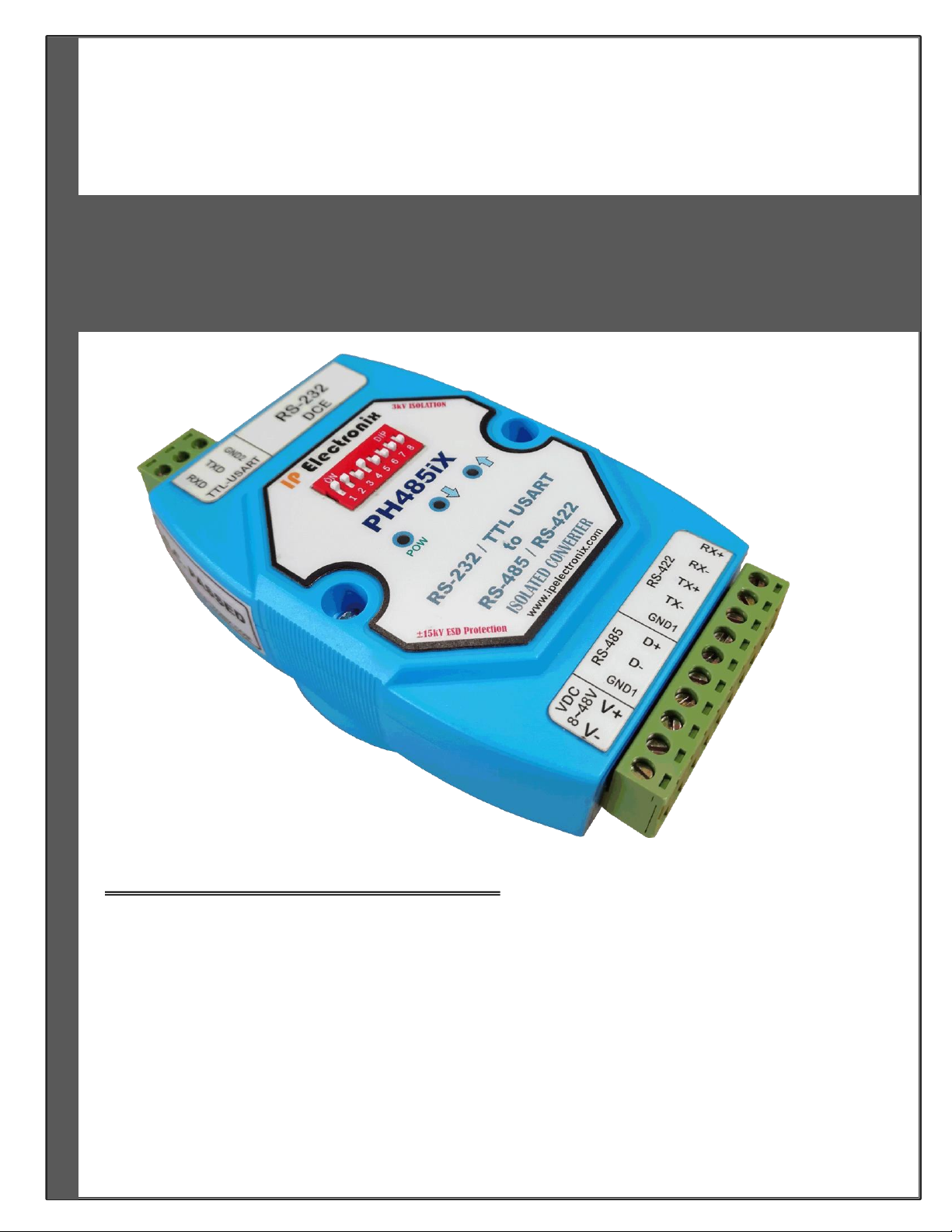
IPEX PH485iX is a Bi-Directional RS-232/TTL UART to RS-485 and RS-422 Converter that converts RxD & TxD
signals of RS-232 standard to differential (Data+ & Data-) signals of RS-485 standard and (RX+, RX- & TX+, TX-)
signals of RS-422 standard at a same time. PH485iX is designed for industrial usage and is useful for Industrial
Automation, Telecommunications, SCADA Systems, DCS Systems and …
Protection against Surge, ESD and EMI is considered in its design and also there is 3kV Electrical and Optical
Isolation between RS-232/TTL UART and RS-485/422 sides. Since RS-485 is a Half-Duplex standard, switching
between Transmit and Receive is done automatically and further signals (such as RTS) are not required. PH485iX
supports Point-to-Point and Point-to-Multi Point Party Line network topologies.
2. Specifications
RS-232 / TTL USART to RS-485/422 Bi-Directional Converter
RS-232 Signal (Full Handshake Support): TxD, RxD, RTS, CTS, DTR, DSR, DCD, GND
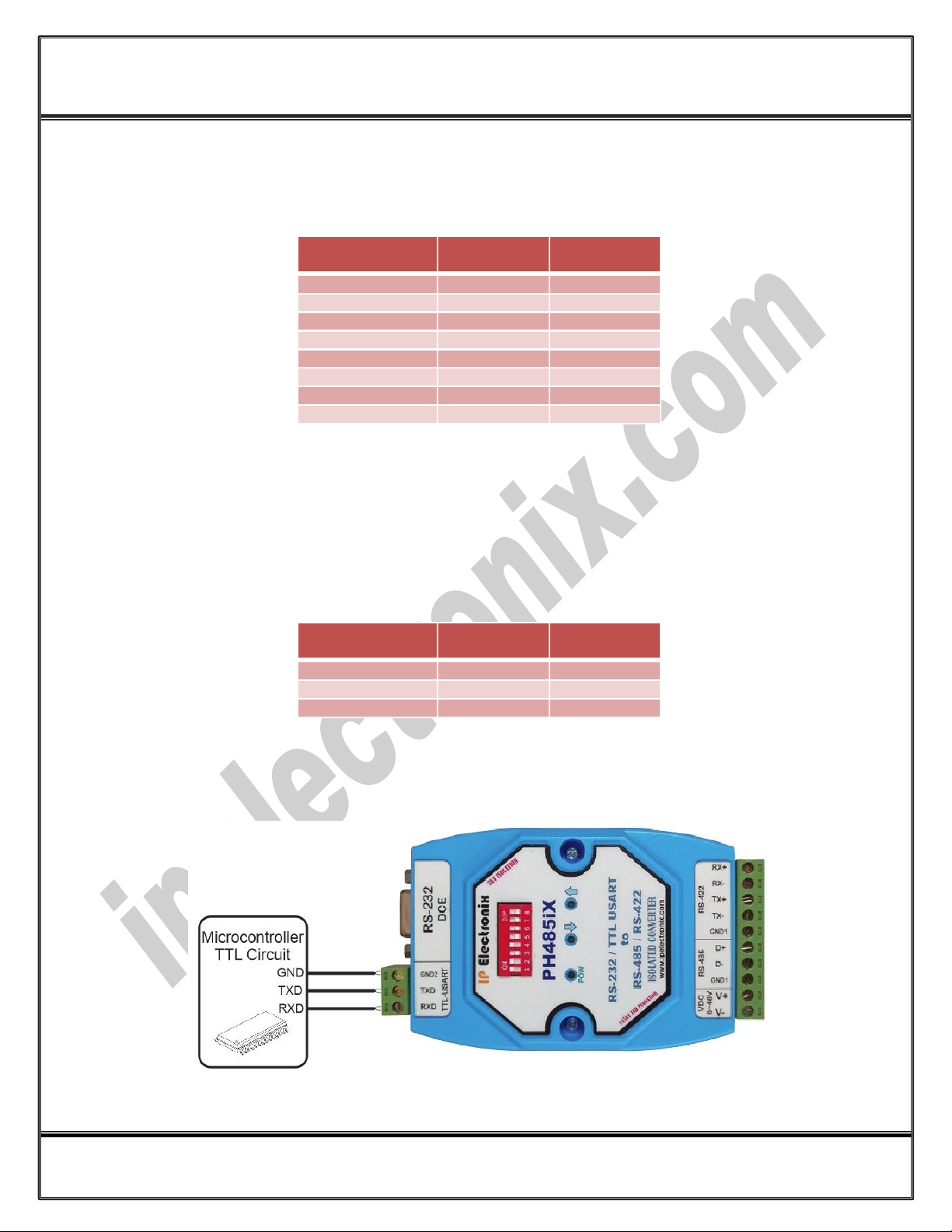
Standard TTL (0~5V) TxD and RxD Signals, proper to directly connect to a Microcontroller
RS-485 Signal: Data+, Data-, GND
RS-422 Signal: TX+, TX-, RX+, RX-, GND
Serial Transmission Speed up to 230.4 kbps
Baud-Rate Type: Auto Switching Baud-Rate
Maximum Communication Distance (RS-485 and RS-422): 1200m (4000 feet)
Loading: RS-485/422 Side Supports up to 32 Nodes
Isolation Protection: 3kV Instantaneous, 500V DC continuous (i-Model only)
Power (Green) LED Indicator
Transmit (Blue) and Receive (Yellow) LED Indicator
Power Supply Input Voltage: +8VDC to +48VDC
Operating Temperature: -10°C to +70°C (+14°F to +158°F)
1 Year Guarantee and 5 Years Support

www.ipelectronix.com
IPEX (IP Electronix) PH485iX: User’s Manual
Page 5 of 12 Doc No. : PH485iX-UM-001
21 August 2019
3. Package Checklist
Before installing the PH485iX, verify that the package contains the following items:
1) PH485iX-Dual 2) Serial Male to Female Cable
4) Document CD-ROM
NOTE: Notify your sales representative if any of the above items is missing or damaged.

www.ipelectronix.com
IPEX (IP Electronix) PH485iX: User’s Manual
Page 6 of 12 Doc No. : PH485iX-UM-001
21 August 2019
4. Top Panel
Green LED: It is turned ON, if the power supply connects to V+ and V- correctly.
Yellow LED: It is blinking if there is a data stream from RS-485/RS-422 side to RS-232 side of the device.
Blue LED: It is blinking if there is a data stream from RS-232 side to RS-485/RS-422 side of the device.
5. Power Supply
Connect a DC voltage in range of +8V to +48V, between V+ and V- terminals. If the power supply connects
correctly, the Green LED should be ON.
NOTE: Do not connect GND1 signal from one side to GND2 signal of other side.

www.ipelectronix.com
IPEX (IP Electronix) PH485iX: User’s Manual
Page 7 of 12 Doc No. : PH485iX-UM-001
21 August 2019
6. Device Settings
RS-422
To use PH485iX as a RS-232 to RS-422 converter, it is not required to set a Baud-Rate and DIP-Switch condition
(on the Top Panel), is not important.
RS-485
Before using PH485iX as a RS-232 to RS-485 converter, it is necessary to set the DIP-Switch (on the top Panel) to
proper condition according to desired Parity, Baud-Rate and . PH485iX supports a wide range Baud-Rates from
1200 bps to 921600 bps.
Set the DIP-Switch condition according to the following table to set the suitable Baud-Rate.
6.1) Parity
Set the Parity type by the DIP-Switch keys number 1 and number 2 on the device. “None”, “Even”and “Odd”
Parity type are supported by PH485iX. The Parity setting are shown in the following table.
6.2) Noisy Environment
In the noisy environments, set the key number 3 ON (up state), otherwise set it OFF (down state)
6.3) Data-Length
7-Bits and 8-Bits Data-Length are supported by PH485iX. Set Data-Length by key number 4.

www.ipelectronix.com
IPEX (IP Electronix) PH485iX: User’s Manual
Page 8 of 12 Doc No. : PH485iX-UM-001
21 August 2019
6.4) Baud-Rate
Four keys from number 5 to number 8 are used to set Baud-Rate as the following table.
Example: Setting Baud-Rate = 9600bps, Data-Length = 8bits and Parity = None, are done as in the table
below.

www.ipelectronix.com
IPEX (IP Electronix) PH485iX: User’s Manual
Page 9 of 12 Doc No. : PH485iX-UM-001
21 August 2019
7. RS-232 Signals
DCE
(PH485iX)
DTE
(PC,PLC,RTU, …)
If Required
1 (DCD)
1 (DCD)
Necessary
2 (RXD)
2 (RXD)
Necessary
3 (TXD)
3 (TXD)
If Required
4 (DTR)
4 (DTR)
Necessary
5 (GND)
5 (GND)
If Required
6 (DSR)
6 (DSR)
If Required
7 (RTS)
7 (RTS)
If Required
8 (CTS)
8 (CTS)
Data Direction Indicator: The Blue light on the top of device blinks if there is a data stream from (RS-232 or TTL
USART) to (RS-485 or RS-422) side (Transmit), also the Yellow light blinks if there is a data stream from (RS-485
or RS-422) to (RS-232 or TTL USART) side (Receive).
8. TTL USART Signals
DCE
(PH485iX)
DTE
Microcontroller
Necessary
GND2
GND
Necessary
TXD
TXD
Necessary
RXD
RXD
Connecting Method: Connect GND2 to Microcontroller Board’s GND, Connect TXD directly to TXD of
Microcontroller and RXD directly to RXD of Microcontroller if your Microcontroller has TTL (0~5V) Logic.

www.ipelectronix.com
IPEX (IP Electronix) PH485iX: User’s Manual
Page 10 of 12 Doc No. : PH485iX-UM-001
21 August 2019
9. RS-485 Connecting Methods
According to the signal labels on the device, the RS-485 signals are: D+(A) and D-(B) that their connections are as
below:
9.1) RS-485: Point to Point Connection
9.2) RS-485: Multipoint Network
NOTICE 1: Normally, D+ connects to D+, and D- connects to D-; but in some devices, D+ and D- signals are vice-
versa, so you should connect D+ to D- and D- to D+ in these cases.
NOTICE 2: In noisy environments, it is better to use GND signal too.
RS-485 Cable: The best cable type for RS-485 side is shielded twisted pair. CAT5 or CAT6 cables are good
choices. Maximum cable length could be 1200m. Connect D+ and D- pins to one pair and GND signal to shield.
Terminator-Resistor: A 120ΩTerminator-Resistor is installed internally and further external Terminator-Resistor
is NOT REQUIRED.

www.ipelectronix.com
IPEX (IP Electronix) PH485iX: User’s Manual
Page 11 of 12 Doc No. : PH485iX-UM-001
21 August 2019
10.RS-422 Connecting methods
According to the signal labels on the device, the RS-422 signals are: TX-, TX-, RX+ and RX- that their connections
are as below:
10.1) RS-422: Point to Point
10.2) RS-422: Multi Drop Network
RS-422 Cable: The best cable type for RS-422 side is shielded twisted pair. Maximum cable length could be
1200m.
Terminator-Resistor: A 120 ohm Terminator-Resistor is installed internally and further external Terminator-
Resistor is NOT REQUIRED.

www.ipelectronix.com
IPEX (IP Electronix) PH485iX: User’s Manual
Page 12 of 12 Doc No. : PH485iX-UM-001
21 August 2019
11.Power Supply
Connect regulated DC Power Supply by the voltage between +8 to +48 Volts between V+ and V- terminals.
Green light on the top of the device will be turned ON if you connect power signals correctly.
12.Guarantee
All products manufactured by IPEX are under warranty regarding defective materials for a period of one year
from the date of delivery to the original purchaser.
13.Technical Support
If you have any technical question or need any technical support, please contact us using this Email address:
support@ipelectronix.com.
Table of contents
Other IPEX Media Converter manuals