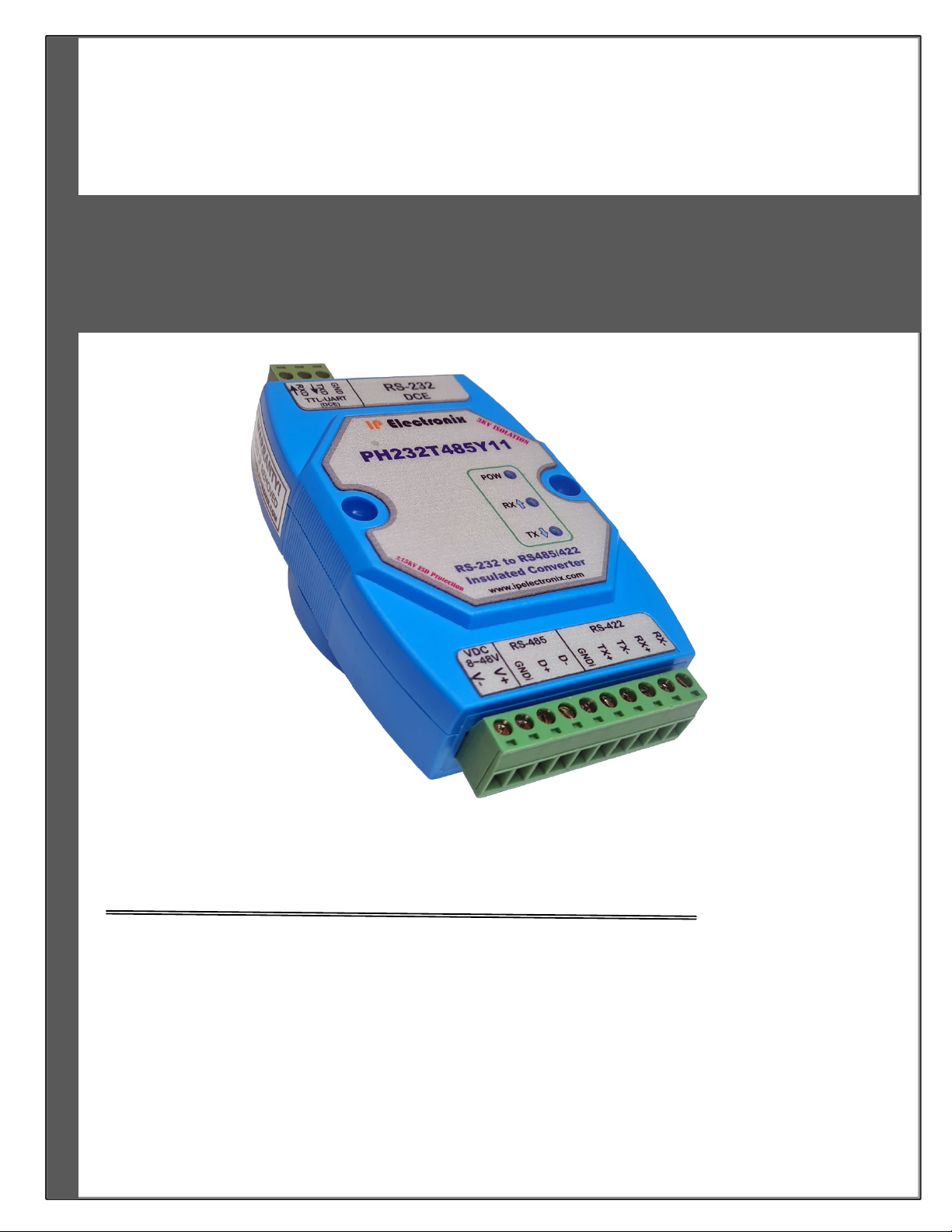
IPEX (IP Electronix) PH232T485Y11: User’s Manual
Page 5 of 18 Doc No.: PH232T485Y11-UM-001
5 April 2023
2. SPECIFICATIONS
RS-232/TTL UART to RS-485/422 Bi-Directional Isolated Converter;
Number of Ports: #1 RS-232 to #1 RS-485/422 Bi-Directional Repeater;
Serial Standard: Meets or Exceeds the Requirements of TIA/EIA-232-F and ITU v.28 Standards;
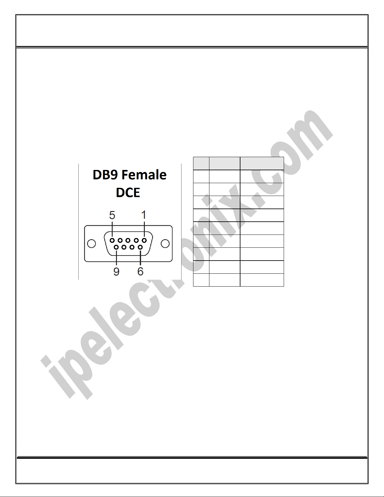
RS-232 Signal (Full Flow Control Support): TxD, RxD, DTR, RTS, DSR, CTS, GND;
RS-232 Parity: Even, Odd, None, Mark and Space;
Standard TTL TxD and RxD Signals, suitable for directly connect to a Microcontroller
Serial Standard: Meets or Exceeds the Requirements of RS-485/422 Standards;
RS-485 Signal: Data+, Data-, GND;
RS-422 Signal: TX+, TX-, RX+, RX-, GND;
RS-485/422 Parity: Even, Odd, None, Mark and Space;
Maximum Communication Distance: 2400m (1200m each side);
Loading: RS-485 and RS-422 Side up to 32 Nodes are supported;
Fully Plug & Play;
Wide Range Power Supply: +8V to +48V DC;
Serial Transmission Speed up to 230.4 kbps;
Power (Green) LED Indicator;
Transmit (Blue) and Receive (Yellow) LED Indicator;
Isolation Protection: 3kV Instantaneous, 500V DC Continuous;
Surge Protection: Embedded 1500W Surge Protection;
Magnetic Isolation: 1.5 kV Built-in;
ESD Protection: Exceeds ±15 kV Using Human-Body Model (HBM);
Dimensions: 26mm x 71.6mm x 122 mm (1.03in x 2.8in x 4.82in);
Operating Temperature: -10°C to +70°C (+14°F to +158°F);
1 Year Guarantee and 5 Years Support.