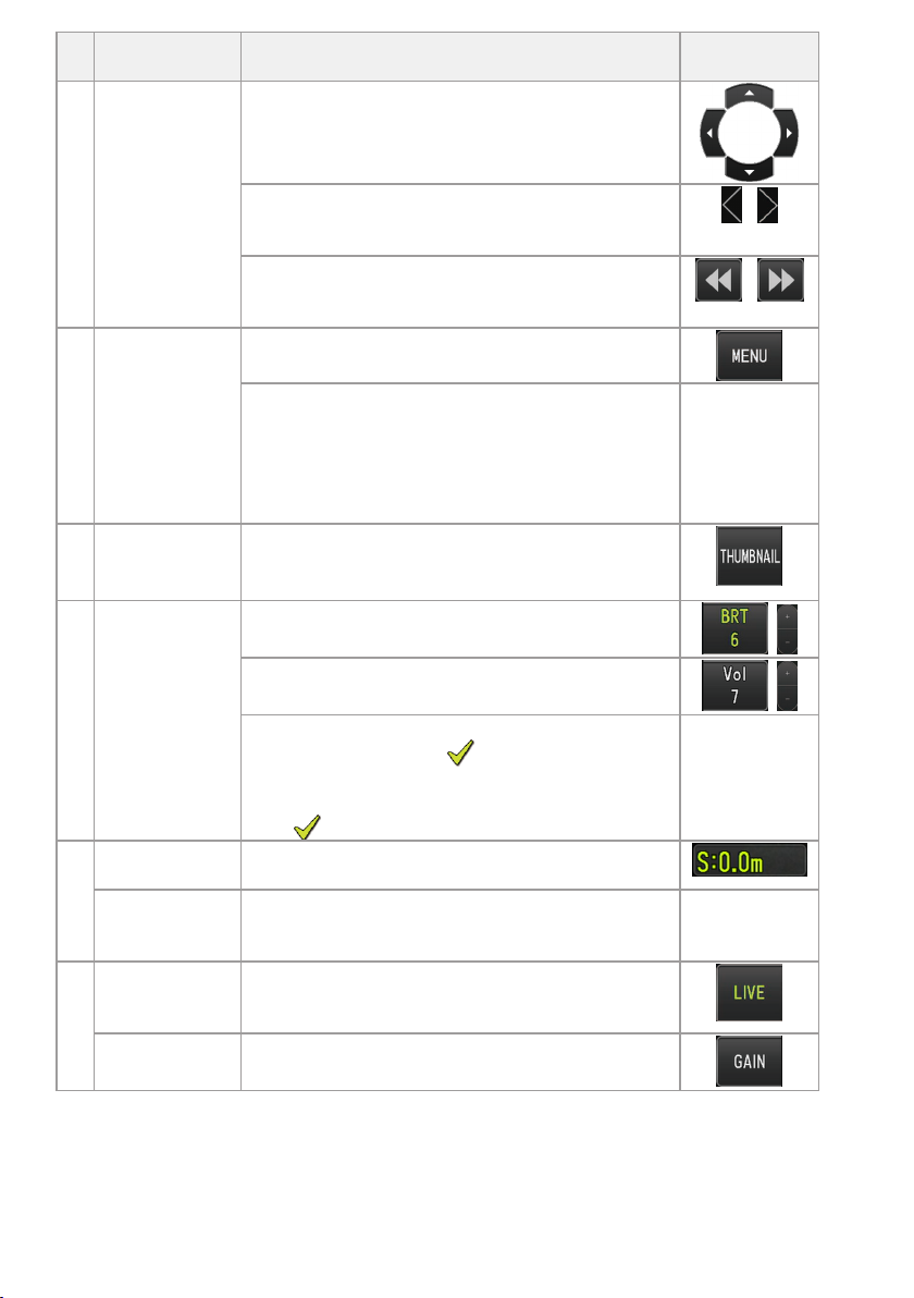
iplex GAir User manual

IPLEX GAir Operation Manual
Before handling this product, please read through and follow the instructions and precautions
in the instruction manual of the IPLEX GAir.
This operation manual is an excerpt from the descriptions and instructions in the instruction
manual of the IPLEX GAir, which includes the setup procedures, the functions of basic operating
components, descriptions on the indicator and menu displays, and safety precautions during
the use of this product.
Intended use
This instrument is intended for inspecting and observing the interior of machinery, equipment,
materials, and other objects, without damaging the object being inspected.
Setting up IPLEX GAir
This product can be set up easily for any user to start inspection immediately.
Simply follow the four steps below to complete the setup.
1 Removing the units from the carrying case
Remove accessories from the carrying case first, and then remove in the order of units and the main
unit from the top cover.
2 Preparing the power supply
When using the battery
Follow the steps below to load the battery.
1INDUSTRIAL ENDOSCOPE
MM4076 01

1. Slide the release knob of the battery door to open the door.
2. Insert the battery while paying attention to the orientation of the battery. Make sure that
the battery is locked in place, and close the door.
When using the external battery
Follow the procedures below to connect the external battery
1. Insert the eight external batteries straight in the external battery case paying attention to
the orientation of the external batteries, and close the latch (A) of the case.
2. Hang the strap of the case over the handle of the drum unit.
2

3. Attach the case connector to the Ext-Batt.-IN terminal on the drum unit.
When using the AC adapter
Follow the procedures below to connect the AC adapter.
1. Open the DC-IN terminal cap (A) on the drum unit.
2. Connect the connector (B) for power supply of the AC adapter to the DC-IN terminal of the
drum unit.
3. Connect the AC power cord to the AC inlet (C) of the AC adapter.
4. Connect the plug of the AC power cord securely to a power outlet.
3

3 Attaching the optical adapter
Name
(A) Optical adapter positioning groove
(B) Connecting screw thread
(C) Distal end
(D) O-ring
(E) First screw thread
(F) Second screw thread
(G) Nut
(H) Optical adapter
1. Holding the optical adapter and the distal end so that they make one straight line each
other, carefully insert the optical adapter into the distal end.
2. Rotate the nut of the optical adapter clockwise until the connecting screw thread passes
over the first screw thread.
3. After passing the first screw thread, rotate the optical adapter main body clockwise while
pushing it gently until the optical adapter main body is engaged with the positioning pin
of the insertion tube and stops rotating anymore.
4. Rotate the nut of the optical adapter clockwise to attach the connecting screw thread to
the second screw thread. Tighten the nut until it stops completely.
4

4 Turning ON the power
1. Turn ON the main switch of the drum unit.
2. Press the [POWER] button ( ) on the base unit for approx. 1.5 to 2 seconds.
The [POWER]LED on the drum unit turns ON in blue and the power of the system turns ON.
The screen display and menu operations become enabled approx. 10 seconds after the [POWER]
button ( ) is pressed.
When the power is turned ON, a list of optical adapters is displayed.
3. Select the optical adapter to use, and press the [MEAS/ENTER] joystick.
The setup is complete.
5

Nomenclature and functions
Live screen ●When [ANGLE] button is ON
No. Button name Function
1FOLDER Shows or hides the [MEAS/ENTER] button (No.6)
2[ZOOM] Shows or hides the zoom level buttons (T, W)
3[BRT] Shows or hides the brightness level buttons (+, -)
4[FRZ]/[STOP] Switches between the live image and frozen image
Stops recording when recording the movie
5[REC]/
[CAPTURE]
[REC]
Records the still image (short-press) and the movie (long-press) on the live
screen
Records still image (short-press) on the freeze screen
[CAPTURE]
Records the still image when recording the movie
6[MEAS/ENTER] Switches between folders
7[MENU] Displays the different menus
8[GAIN] Switches the gain mode
9[ANGLE/INDEX]
Shows or hides the angulation operation button (No.14)
Tapping the button each time repeats switching the angulation operation
button to Show, Move or Hide.
Adds index mark when recording the movie
10 [LIVE] Moves to the live screen when in the freeze screen mode
11 [VIEW] Moves to the view screen
12 [THUMBNAIL] Moves to the thumbnail screen
13 [MEASURE] Moves to the scaler measurement screen
14 Angulation
operation Perform the angulation operation
Performing the angulation operation
1. Press the ANGLE button to display the angulation operation button.
2. Press the angulation operation button of the desired direction for observation.
Recording images
6

If you use the SDHC card for the first time, be sure to format the SDHC card using this instrument
before recording images. For detail procedures, refer to IPLEX GAir instruction manual.
Recording the still image
1. Short-pressing the [FRZ] button while the live screen is displayed allows you to freeze the
image.
2. Short-pressing the [REC] button while the freeze screen is displayed allows you to save the
image in the folder.
Recording the movie
1. While the live screen is displayed, long-press the [REC] button.
2. After a still image is recorded, the movie recording confirmation dialog appears.
3. Select <YES>, and start recording the movie.
4. Short-press the [REC] button to end recoding the movie.
Playing back the recorded image
View screen
1. Short-press the [VIEW] button to display the latest recorded image.
2. Operate the [MEAS/ENTER] joystick to right or left to switch the image.
Thumbnail screen
1. Short-press the [THUMBNAIL] button to display the thumbnail screen.
2. Operate the [MEAS/ENTER] joystick to four directions to select the image, and press the [OK]
button to display the view screen.
7

LCD monitor nomenclature
No. Icon/
Indicator Name
1- Folder name
2- Optical adapter name
3
/
Distal end temperature indicator
4- Insertion length information
5Gravity direction icon
6- Zoom level
7- Brightness level
No. Icon/
Indicator Name
8- Date/Time
9- Grid
10 SD card icon
11 -Number of images that can be
recorded*1
12 External battery indicator
13 Battery indicator
14 Freeze icon
15
Constant video recording icon
Recording movie icon
Recording sound icon
16 /Angulation speed icon
17 Wireless LAN icon
18 Image rotation stop icon
19 Angle centering icon
20 /LED icon
21 Gain mode icon
22 - Title
23 - Logo
24 - File name
25 Note icon
26 Movie icon
27 Check mark icon
28 Measurement icon
29 Constant video icon
30 Sound icon
31
Play movie icon
Pause movie icon
End movie playback icon
32 - Movie playback time
33 - Movie playback position bar
34 - Index mark
35 - Total movie duration
Live screen
Freeze screen
Thumbnail screen
View screen
8

Operating the product using the remote control unit
Buttons, Levers
and Joysticks Function Touch panel
(A) [ZOOM] lever Uses the zoom function.
Skips (backward and forward) to the index mark
positions when playing back or pausing a movie on the
view screen.
/
(B) [ANGLE/SPEED]
joystick (press)
Switches the angulation speed of the distal end of the
insertion tube.
-
[ANGLE/SPEED]
joystick (joystick
operation)
Operates the angulation of the distal end of the
insertion tube.
(C) [VIEW] button Displays the view screen when there is a still image
file in the selected folder.
(Tapping this button while the view screen is
displayed will show the live screen.)
[VIEW] button
(long-press)
Switches the illumination in the order of turning ON
(high beam), normal beam (eco) and turning OFF.
-
(D) [MEAS/ENTER]
joystick (press
the button)
Selects the menu, etc.
Decides the specified point on the measurement
screen.
Decides the layout of the note information on the note
display screen.
-
Adds the index marks while recording the movie.
Displays the scaler measurement screen.
Pressing this button while playing back the movie on
the view screen will pause or resume playing back the
movie.
-
[MEAS/ENTER]
joystick (joystick
operation)
Selects a menu.
Switches the selected image on the thumbnail screen.
Tap on the
screen
9

Buttons, Levers
and Joysticks Function Touch panel
Switches a destination folder to save the image on the
live screen.
Moves the cursor or note information.
Displays the previous image by operating this joystick
to the left and displays the next image by operating
this joystick to the right on the view screen.
/
When playing back the movie on the view screen,
operating the joystick upward (downward) allows to
perform fast forward (fast reverse) respectively
/
(E) [MENU] button Shows or hides the menu screen.
Pressing this button while displaying the constant
video playback screen or the note display screen
switches the touch panel monitor display between
“Operating with the touch panel and the
[MEAS/ENTER] joystick” and “Operating with only the
touch panel”.
-
(F) [THUMBNAIL]
button
Displays the thumbnail screen.
(Tapping this button while the thumbnail screen is
displayed will show the live screen.)
(G) [BRIGHT] lever Changes the brightness setting.
Adjusts the sound volume on the view screen or the
constant video playback screen.
On the thumbnail screen, operating this lever upward
shows or hides the mark ( ) of the selected
thumbnail image.
Operating this lever downward shows or hides the
mark ( ) of all thumbnail images.
-
(H) [LENGTH] button
(short-press)
Shows the length setting dialog.
[LENGTH] button
(long-press)
Switches the rotation mode according to the gravity
direction of the live image.
Tap the center
of the live
screen.
(I) [LIVE] button
(except live
screen)
Displays the live screen.
[LIVE] button
(live screen)
Switches the gain mode.
10

Buttons, Levers
and Joysticks Function Touch panel
(J) [CENT] button Centers the distal end of the insertion tube. Tap the center
of the screen
when the
angulation
operation
button is
displayed.
(K) [FREEZE] button Freezes or unfreezes the observation image.
Records a still image when movie recording is in
progress. /
(L) [RECORD] button
(short-press)
Records a still image.
Ends recording the sound during sound recording.
Ends recording the movie during movie recording.
[RECORD] button
(long-press)
Starts recording the movie.
(E)
+
(I)
[MENU] button +
[LIVE] button
(press at the
same time)
Turns ON or OFF the LCD monitor.
Even while the LCD monitor is turned OFF, the
constant video is recorded.
When you turn ON the power again, the live screen is
displayed.
-
(F)
+
(J)
[THUMBNAIL]
button + [CENT]
button (press for
2 seconds or
more at the
same time)
Turns OFF the base unit. -
- - Switches the folder.
- - Shows, moves or hides the [CURSOR/OK] button.
TIP:
If multiple functions are assigned to the button, the time to press the button distinguishes each
function. In this manual, the term “press” or “short-press” is used to indicate pressing a button for a
short duration, while “long-press” means holding down a button approx. one second.
Displaying the menu screen
Press the [MENU] button on the LCD monitor to display the menu screen.
11

Using the live screen or freeze screen
Mainmenu Submenu Item
<TITLE>
-
Inputs a title.
Puts a title on the live screen and recorded images. Up to 30
characters can be input.
<WHITE
BALANCE>
-
Adjusts the white balance (Live screen only).
Specifies whether to adjust the white balance or not.
l<CANCEL>: Do not adjust
l<EXECUTE>: Adjust
When replacing the parts like the optical adapter, adjust the white
balance by acquiring an image of a white object such as a piece of
paper, from a distance of 50 to 60 mm.
This option cannot be used for the freeze screen.
<IMAGE
MODE>
<IMAGE
INVERSION>
Inverts the live image.
You can invert the live image displayed on the LCD monitor.
The available options are <OFF>, <HORIZONTALLY REVERSE>,
<VERTICALLY REVERSE> and <ROTATE>.
This option cannot be used for the freeze screen.
<SHARPNESS> Adjusts the sharpness of the image
The sharpness level increases from left to right (4 levels).
This option cannot be used for the freeze screen.
<SATURATION> Adjusts the color of the image
l<MONOTONE>: Displays the image in monochrome.
l<NATURAL>: Displays the standard observed image.
l<VIVID>: Emphasizes the entire image.
This option cannot be used for the freeze screen.
<DYNAMIC
NOISE
REDUCTION>
Makes the settings for the dynamic noise reduction.
You can specify whether to enable or disable the dynamic noise
reduction.
l<OFF> : Disable
l<ON> : Enable
This option cannot be used for the freeze screen.
12

Mainmenu Submenu Item
<IMAGE
ORIENTATION>
Rotates the live image in gravity direction.
You can select < OFF>, <AUTO-ORIENTATE>, or <ZOOM-
ORIENTATE>.
See "Rotating the live images automatically"(page 19).
This option cannot be used for the freeze screen.
This option cannot be used when the side-view optical adapter is
used.
<DISTORTION
CORRECTION
MODE>
Corrects the distortion of the image.
You can specify the method to correct the distortion of the image so
that it looks like a flat surface.
When using the optical adapter 220D:
l<OFF> : Disable
l<DEWARP220>: Corrects the distortion shrinked outward.
(Correction range: 220-degree field of view)
l<DEWARP180>: Corrects the distortion shrinked outward.
(Correction range: 180-degree field of view)
l<DEWARP120>: Corrects the distortion shrinked outward.
(Correction range: 120-degree field of view)
When using the optical adapter other than 220D:
l<OFF> : Disable
l<DEWARP120>: Corrects the distortion of the entire image.
l<SIDE STRETCH LOW>: Softly corrects the distortion
shrinked outward.
l<SIDE STRETCH HIGH>: Strongly corrects the distortion
shrinked outward.
This option cannot be used for the freeze screen.
This option cannot be used if any optical adapter is not selected.
<GRID> Displays the grid on the screen.
You can select the grid view from OFF or three grid types.
The grid is displayed on the live screen.
<RECORD
MODE>
<FILE NAME
MARK>
Automatically adds a file mark to the end of the file name of the
recorded image.
l<OFF>: The mark is not added.
l<ON>: The mark is added.
You can select the mark to be added when recording the image. The
marks can be selected from None, _A, _B, _C and _D.
13

Mainmenu Submenu Item
<SD FORMAT> Formats (initializes) the SDHC card.
l<CANCEL>: Does not format the SDHC card.
l<EXECUTE>: Formats the SDHC card.
CAUTION:
Never remove the SDHC card while formatting the SDHC.
TIP:
Formatting the SDHC card deletes all data.
<microSD
FORMAT>
Formats (initializes) the microSDHC card.
l<CANCEL>: Does not format the microSDHC card.
l<EXECUTE>: Formats the microSDHC card.
CAUTION:
Never remove the microSDHC card while formatting the microSDHC
card.
TIP:
Formatting the microSDHC card deletes all data.
<MOVIE FRAME
RATE>
Select the frame rate for movie recording.
l<30 Frames/Sec>
l<60 Frames/Sec>
<STILL AUDIO> Makes settings for sound recording.
You can specify whether to record the sound while recording the
still image or the movie. A headset is required for recording the
sound.
l<OFF>: Disable
l<ON>: Enable
CAUTION:
Even though <STILL AUDIO> is set to <ON>, the sound will not be
recorded if a headset is not connected.
<CONSTANT
VIDEO>
Make settings for constant video recording.
You can specify whether to record the constant video or not while
the live screen is displayed.
l<OFF>: Disable
l<ON>: Enable
<SYSTEM
SETUP>
<DISPLAY> Selects the information to be displayed on the screen.
You can select whether to display the zoom, brightness, date/time,
title, logo, optical adapter, insertion length and gravity direction.
14

Mainmenu Submenu Item
<DATE TIME> Specifies date and time.
You can specify date and time.
<LANGUAGE> Specifies the display language.
You can select the language used for menus and messages.
English and other languages are supported. The default setting is
English.
<VERSION> Displays the version information.
You can display the software version of the base unit, initial data
version and the upgrade information of the system.
<START UP> Saves the settings when the power was turned OFF.
By saving the settings when the power was turned OFF, you can
specify whether to automatically apply such settings or not when the
power is turned ON next time.
l<OFF>: Disable. (Applies the default settings when the
power is turned ON next time.)
l<ON>: Saves the settings when the power was turned OFF,
and applies such settings when the power is turned
ON next time.
(Settings that can be saved: Brightness adjustment,
zoom factor, gain mode, and high beam or normal
beam (eco))
<LCD
BACKLIGHT>
Specifies the brightness of the back light of the LCD monitor.
The brightness level increases from bottom to top (5 levels).
<ANGLE SPEED> Specifies the angulation speed.
The angulation speed can be selected between <SLOW> and
<FAST> (2 levels).
<LENGTH
UNIT>
Selects the unit of insertion length.
You can select <meter> or <foot/inch>.
<LENGTH
FORM>
Selects the method to display the insertion length.
You can select <SECTION LENGTH> or<COMBINED LENGTH>.
See "Displaying the insertion length"(page 21).
<CLEAR DRAIN
ERROR>
Clears the drain error of the compressor.
This option cannot be used if there is no drain error when you turn
ON the power of this instrument or after the drain error is cleared.
15

Mainmenu Submenu Item
<REMOTE
CONTROLLER
VIBRATION>
Sets the vibration of the remote control unit.
You can set whether to vibrate the remote control unit or not in the
following cases.
oWhen the insertion tube is pulled out from the inspection
object keeping the distal end of the insertion tube bent.
(When <SCOPE PROTECTION> is set to <ON>.)
oWhen an error occurs.
oWhen the rotation of the live image according to the gravity
direction becomes disabled during angulation operation.
oWhen the remote control unit is connected.
oWhen the power of the base unit is turned OFF using the
remote control unit.
This option cannot be used when the remote control unit is not
connected.
<SCOPE
PROTECTION>
Displays the error message when the insertion tube is pulled out
from the inspection object keeping the distal end of the insertion
tube bent.
You can set whether to display the message and to vibrate the
remote control unit when the insertion tube is pulled out from the
inspection object keeping the distal end of the insertion tube bent.
See "Detecting when pulling out the bent insertion tube"(page 23).
<WIRELESS
MODE>
<CONNECT> Specifies the wireless communication.
l<OFF>: Disable
l<ON>: Enable
<DEFAULT> Initializes the wireless settings.
l<CANCEL>: Does not format the wireless settings.
l<EXECUTE>: Formats the wireless settings.
<PLAY
CONSTANT
VIDEO> -
Plays back the constant video.
Plays back the constant videos automatically if there are recorded
constant videos.
<SELECT
OPTICAL
ADAPTER> -
Displays the optical adapter list.
You can set the optical adapter that is connected to the system.
This option cannot be used for the freeze screen.
<ROTATE>
-
Displays the screen by rotating it 180 degrees.
You can display the screen of the LCD monitor by rotating it 180
degrees.
To return to the original state, select <OFF> in the <ROTATE> menu.
16

Using the thumbnail screen or the view screen
You can make the following settings in the menu displayed on the thumbnail screen.
Menu Available settings
<DELETE> Deletes the recorded image.
l<CANCEL>: Do not delete the image.
l<EXECUTE>: Delete the image.
You can delete the images selected on the thumbnail screen or images with the
mark ( ).
<MOVE FILE> Moves image files from one folder to another.
You can move the recorded images to a different folder.
The images currently selected on the thumbnail screen or images with the mark (
) are moved.
<RENAME FILE> Changes the image file name.
You can change the name of the recorded image file (30 characters or less).
<CHANGE
FOLDER>
Switches between the folder for recording and the folder playing back the
image.
You can switch between the folder for recording and the folder for playing back
the image.
The default setting is “DCIM\100IPLEX”.
You can change to the folder displayed on the menu screen.
<MAKE
FOLDER>
Creates a new folder for recording and playing back the image.
You can create a folder for recording and playing back the image.
Up to 1,000 folders can be created in one folder.
<RENAME
FOLDER>
Renames a folder for recording and playing back the image.
You can rename a folder for recording and playing back the image.
The following settings can be made on the view screen menu.
Menu Available settings
<DELETE> Deletes the recorded image.
l<CANCEL>: Do not delete the image.
l<EXECUTE>: Delete the image.
You can delete the image displayed on the view screen.
<NOTE> Inputs the note information (text/mark/free drawing) to the desired position on
the screen (view screen for still image only).
You can input the note information (text/mark/free drawing) on the still image that is
being played back.
17

Inputting a title
Inputting a title using the software keyboard
1. Select the input mode.
2. Select the text buttons you want.
To delete texts
lTo delete a single text, move the cursor to it and select <DELETE>.
lTo delete all input texts, select <CLEAR>.
To input a space
Move the cursor to the location where you want to input the space, and select <SPACE>.
3. Select <EXECUTE>.
The title you input is displayed on the live screen and the freeze screen.
Inputting a title by selecting a preset title
1. Select <PRESET>.
A list of preset titles is displayed. To cancel selecting the preset title, press the close button (x)
to close the screen.
18

2. Select the text strings from the preset title list.
The text string you selected appears in the title field and the list is closed.
Repeat steps 1and 2to complete inputting the title.
TIP:
The preset title list has nine pages. To change pages, select the text string in line 1 or line 6 of
the list and operate the [MEAS/ENTER] joystick upward or downward, or press the up button or
the down button on the right side of the screen.
3. Select <EXECUTE>.
The title you selected is displayed on the live screen and the freeze screen.
Displaying the gravity direction
Using the acceleration sensor built in the distal end of the insertion tube, you can display the gravity
direction on the live screen according to the tilt or rotation of the distal end of the insertion tube.
The gravity direction icon expresses the surface that is cut vertically against the inserting direction of
the distal end of the insertion tube. The brown area indicates the ground side (gravity direction) and
the blue area indicates the sky side (direction opposite to gravity).
The white circle in the icon indicates the center of the ground side (gravity direction) and the red
circle indicates the center of the sky side (direction opposite to gravity).
TIP:
lThe gravity direction icon is displayed when using the forward-view optical adapter.
lYou can show or hide the gravity direction icon by selecting the menu - <SYSTEM SETUP> -
<DISPLAY>.
Rotating the live images automatically
Using the acceleration sensor built in the distal end of the insertion tube, you can display the live
image by rotating it so that the downward direction of the image always indicates the gravity
direction.
There are two methods to rotate the image as shown below.
19

<AUTO-ORIENTATE> Rotates the live image according to the gravity direction.
The displayed image contains the area without data (black area in the picture
on the left).
<ZOOM-ORIENTATE> Rotates the live image according to the gravity direction, and displays the
image by zooming digitally so that the area without data will not be
contained.
TIP:
The image may become slightly coarse due to digital zoom.
Tapping on the live screen switches in the order of <AUTO-ORIENTATE>, <ZOOM-ORIENTATE> and
<OFF>.
TIP:
lThe rotation mode of the live image can also be changed on the <IMAGE ORIENTATION> menu.
lThe rotation mode of the live image can also be changed by long-pressing the [LENGTH] button on
the remote control unit.
lIn <AUTO-ORIENTATE> or <ZOOM-ORIENTATE> mode, when the insertion tube is bent in
proximity of the gravity direction or the direction opposite to gravity, the automatic rotation of the
live image stops. At this time, the image rotation stop icon ( ) appears on the live screen, and if
the <REMOTE CONTROLLER VIBRATION> menu is set to <ON>, the remote control unit vibrates.
lDisplay the angulation operation button on the LCD monitor and then tap the center of the screen,
or press the [CENT] button on the remote control unit to automatically rotate the live image again.
20
Table of contents
Other iplex Industrial Equipment manuals
Popular Industrial Equipment manuals by other brands

IDEAL
IDEAL Exalt quick start guide

Graco
Graco SaniForce STU Operation

Premier
Premier 127 Installation, Inspection, Operation & Maintenance Guide

Festo
Festo EPCS-BS operating instructions

HMS Networks
HMS Networks Anybus Communicator PROFINET to EtherCAT... user manual

ABB
ABB Relion 615 series Point List Manual